INTRODUCTION
To increase the beam-wave interaction efficiency and output power is one of the most important considerations of high-power microwave sources (Bugaev et al., Reference Bugaev, Cherepenin, Kanavets, Klimov, Kopenkin, Koshelev, Popov and Slepkov1990; Friedman & Serlin, Reference Friedman and Serlin1992; Moreland et al., Reference Moreland, Schamiloglu, Lemke, Korovin, Rostov, Roitman, Hendricks and Spencer1994; Eltchaninov et al., Reference Eltchaninov, Korovin, Rostov, Pegel, Mesyats, Rukin, Shpak, Yalandin and Ginzburg2003; Korovin et al., Reference Korovin, Kurkan, Loginov, Pegel, Polevin, Volkov and Zherlitsyn2003; Liu et al., Reference Liu, Xiao, Chen, Shao, Hu and Wang2008a, Reference Liu, Shao, Yang, Song, Chen, Sun and Zhang2008b; Xiao et al., Reference Xiao, Lin, Song, Chen and Liu2007, Reference Xiao, Liu and Chen2008a). The highest power so far was achieved by the multiwave Cerenkov generator (Bugaev et al., Reference Bugaev, Cherepenin, Kanavets, Klimov, Kopenkin, Koshelev, Popov and Slepkov1990), and relativistic klystron amplifier (Friedman & Serlin, Reference Friedman and Serlin1992; Serlin & Friedman, Reference Serlin and Friedman1994) in the 1990s. In multiwave Cerenkov generator, the power of 15 GW in a 3-cm-wavelength band with efficiency of 50% was reported, but this result needs a further verification by the calorimeter (Barker & Schamiloglu, Reference Barker and Schamiloglu2001). In relativistic klystron amplifier, the power of 15 GW at instantaneous efficiency of about 40% was extracted; however, the operation was erratic both in peak power and pulse duration. Good shot-to-shot reproducibility can be observed at the power level of about 6 GW, corresponding to an efficiency of 17% (Friedman & Serlin, Reference Friedman and Serlin1992).
Recently, the scientists in Russia have achieved some important experiments results. In 2003, peak microwave power of 5.3 GW with efficiency of 30% was obtained in an S-band resonant backward wave oscillator (BWO) (Korovin et al., Reference Korovin, Kurkan, Loginov, Pegel, Polevin, Volkov and Zherlitsyn2003). Based on super radiance, ultrashort X-band pulses of about 3 GW peak power and 0.6–0.7 ns width were produced with a power conversion efficiency of 150–180% (Eltchaninov et al., Reference Eltchaninov, Korovin, Rostov, Pegel, Mesyats, Rukin, Shpak, Yalandin and Ginzburg2003). In 2008, a microwave power of 4.3 GW with efficiency of 31%, and power of 5 GW with efficiency of 22% were obtained in an X-band BWO with a modulating resonant reflector (Klimov et al., Reference Klimov, Kurkan, Polevin, Rostov and Tot'meninov2008). In China, a power of 4.1 GW and efficiency of 26% was reported in a relativistic extended-interaction-cavity oscillator (Huang et al., Reference Huang, Jin, Lei, Luo, Zhang, Gan and Ju2008). From these results it can be concluded that, at present, the maximum power is up to 5 GW, however, the efficiency is limited to about 30% except for the super radiance.
We have made great efforts to enhance the microwave power and efficiency (Chen et al., Reference Chen, Liu, Huang, Song, Fan and Wang2002; Liu et al., Reference Liu, Xiao, Chen, Shao, Hu and Wang2008a, Reference Liu, Shao, Yang, Song, Chen, Sun and Zhang2008b), and presented a serious of HPM sources (Liu et al., Reference Liu, Xiao, Chen, Shao, Hu and Wang2008a, Reference Liu, Shao, Yang, Song, Chen, Sun and Zhang2008b; Teng et al., Reference Teng, Liu, Shao and Tang2009; Xiao et al., Reference Xiao, Zhang, Liang, Teng, Chen, Shao, Liu and Lin2008b, Reference Xiao, Chen, Zhang and Sun2009a, Reference Xiao, Zhang, Shao and Sun2009b, Reference Xiao, Sun, Chen, Zhang and Shao2009c, Reference Xiao, Song, Song, Sun, Shao and Chen2010), among which the klystron-like RBWO that was proposed based on the RBWO with a resonant reflector (RBWO-RR) is extremely important (Xiao et al., Reference Xiao, Chen, Zhang and Sun2009a). This article briefly outlines the physics analysis that reveals the possibility of increase in the conversion efficiency and power handling capacity and demonstrates the simulation and experiment results.
PHYSICS ANALYSIS
As shown in Figure 1, the basic distinguishing feature of the klystron-like RBWO compared to the RBWO-RR is the introductions of a modulation cavity and an extraction cavity (Xiao et al., Reference Xiao, Chen, Zhang and Sun2009a). The modulation cavity separates the slow wave structure (SWS) into two sections, and the extraction cavity is added to the end of the SWS. The operation modes of the two cavities are approximately TM020. The cavity radius r and axial length L roughly satisfy μ02/k < r < μ03/k and L < λg/4, where μ02 and μ03 are the second and the third roots of the zero order Bessel function, k is the wave number, and λg is the guide wavelength.

Fig. 1. (Color online) Structure by the klystron-like RBWO.
The phase space plots for klystron-like RBWO and RBWO-RR (representing the structure with modulation cavity and extraction cavity removed in Fig. 1) are displayed in Figures 2 and 3, which illustrate that in the klystron-like RBWO, the energy spread of the modulated beam electrons decreases greatly after the modulation cavity, and the well-modulated electrons lose energy continuously (Xiao et al., Reference Xiao, Chen, Zhang and Sun2009a). As shown in Figure 4, both the large amplitude and phase of the axial electric field in the extraction cavity are beneficial for further recovering energy from electron beam. Therefore, the klystron-like RBWO combines transition radiation with Cerenkov radiation, which leads to a larger efficiency enhancement, compared with the single mechanism of Cerenkov radiation in a conventional RBWO (Gunin et al., Reference Gunin, Klimov, Korovin, Kurkan, Pegel, Polevin, Roitman, Rostov, Stepchenko and Tot'meninov1998; Chen et al., Reference Chen, Liu, Huang, Song, Fan and Wang2002).

Fig. 2. Phase space plot for the klystron-like RBWO.

Fig. 3. Phase space plot for the RBWO-RR.

Fig. 4. (Color online) Axial electric field distribution at beam average radius r = 4.2 cm in the klystron-like RBWO and RBWO-RR.
Furthermore, the operation mode of the resonant reflector in the klystron-like RBWO is TM021. As shown in Figure 5, the maximum electric field appears in the middle position, not on the corner wall, as is the case in the TM020 reflector that is generally used in previous BWO-RR (Klimov et al., Reference Klimov, Kurkan, Polevin, Rostov and Tot'meninov2008; Li, Reference Li2008), which could increase the power handling capacity. Moreover, similar to the klystron, the self-field of the intense beam can provide significant electrostatic insulation against vacuum breakdown at the extraction cavity (Friedman et al., Reference Friedman, Krall, Lau and Serlin1990).

Fig. 5. SUPERFISH simulation of the resonant reflector, showing the electric field distribution in the TM021 cavity (a) and TM020 cavity (b).
SIMULATION RESULTS
The klystron-like RBWO is simulated with the particle-in-cell code KARAT (Tarakanov, Reference Tarakanov1998). The injected voltage is trapezoid, with rise time 20 ns, flat top 45 ns, and fall time 20 ns. When the diode voltage is 1.1 MV, and current is 16.6 kA, a microwave with power of 7.4 GW, efficiency of 41%, frequency of 4.3 GHz, and pulse width of 49 ns is generated, as shown in Figures 6 and 7. The dependence of microwave power and efficiency with diode voltage is illustrated in Figure 8. The efficiency exceeds 40% at a wide voltage range of 760–1120 kV. When the diode voltage is 850 kV, the output power is 5 GW with a maximum efficiency of 49%. After the modulation cavity and extraction cavity are removed, the power and efficiency decrease significantly, only half of those obtained in the klystron-like RBWO (Fig. 9).

Fig. 6. Microwave power of the klystron-like RBWO: diode voltage 1.1 MV, diode current 16.6 kA, magnetic field strength 2 T.

Fig. 7. Frequency spectrum of the radial electric field in the klystron-like RBWO.

Fig. 8. (Color online) Microwave power and efficiency versus diode voltage for the klystron-like RBWO.

Fig. 9. (Color online) Microwave power and efficiency versus diode voltage for the RBWO-RR.
EXPERIMENT RESULTS
An experimental study of the klystron-like RBWO was performed using the TPG-2000 high-current electron-beam accelerator. The accelerator consists of a coaxial pulse forming line, a built-in Tesla transformer, a spark gas gap switch with a gas-blowing system, and a coaxial pulse transmission line, which can operate in the regime of single pulse at a maximum voltage of 2 MV with pulse duration of 65 ns.
The experimental set-up is shown in Figure 10. The generated microwave was radiated into the atmosphere through a conical horn antenna with a diameter of 90 cm. The dielectric window has been processed to be periodic triangular surface with slope angle π/4 and period 2 mm to increase the breakdown threshold at the vacuum side (Chang et al., Reference Chang, Liu, Huang, Chen and Fang2009, Reference Chang, Zhu, Liu, Fang, Xiao, Chen, Shao, Li, Huang, Zhang and Zhang2010a, Reference Chang, Liu, Fang, Tang, Huang, Chen and Zhang2010b). A balloon filled with SF6 was fixed outside of the window to prevent air breakdown.

Fig. 10. (Color online) Photograph of the experiment set-up.
In the experiments, the diode voltage and the diode current were measured by a capacitor divider located at the end of the transmission line and a Rogowski coil placed in the diode region, respectively. The output microwave signal was received by an open-ended rectangular waveguide with cross section of 47.6 × 22.2 mm2. The rectangular waveguide is 50 cm long, and the outer wall of the waveguide was pasted with absorbers in order to decrease the frequency dependence of the effective section (Klimov et al., Reference Klimov, Kurkan, Polevin, Rostov and Tot'meninov2008; Zhang et al., Reference Zhang, Ning, Shao, Chen and Song2009). The receiving antenna was situated at a distance of 9 m away from the phase center of the radiation horn. The received microwave signal was detected by an M/A-COM radio frequency detector via 80 dB attenuators. The microwave power was calculated based on the integral of power density in the radiation field. The measurement uncertainty of the microwave power is estimated to be less than 20%. The microwave power can also be monitored by the online circular waveguide directional coupler (coupling degree −55 dB) located before the horn (shown in Fig. 10). The coupled microwave was detected by a detector via 65 dB attenuators.
When the diode voltage and diode current were kept at 1.1 MV and 16.4 kA, and the magnetic field at 2.2 T, the measured power density distribution is shown in Figure 11, which was in agreement with the theoretic pattern, indicating that the radiation mode was TM01. The integrated power was 6.5 GW, corresponding to an efficiency of 36%. Typical experimental waveforms of the diode voltage, diode current, and two output microwave signals measured in the radiation field and through online directional coupler are presented in Figure 12. The microwave power measured in the radiation field was 6.5 GW, and the pulse width was about 38 ns, close to that obtained by particle-in-cell simulation, indicating that there was no obvious pulse shortening. The power monitored by the online coupler was 7.0 GW, about 8% larger than that measured in the radiation field.

Fig. 11. (Color online) Power density distribution.

Fig. 12. (Color online) Waveforms of the diode voltage (1), diode current (2), microwave detector signals through the online coupler (3) and in the radiation field (4) (diode voltage 1.1 MV, diode current 16.4 kA, microwave power 6.5 GW, 20 ns/div).
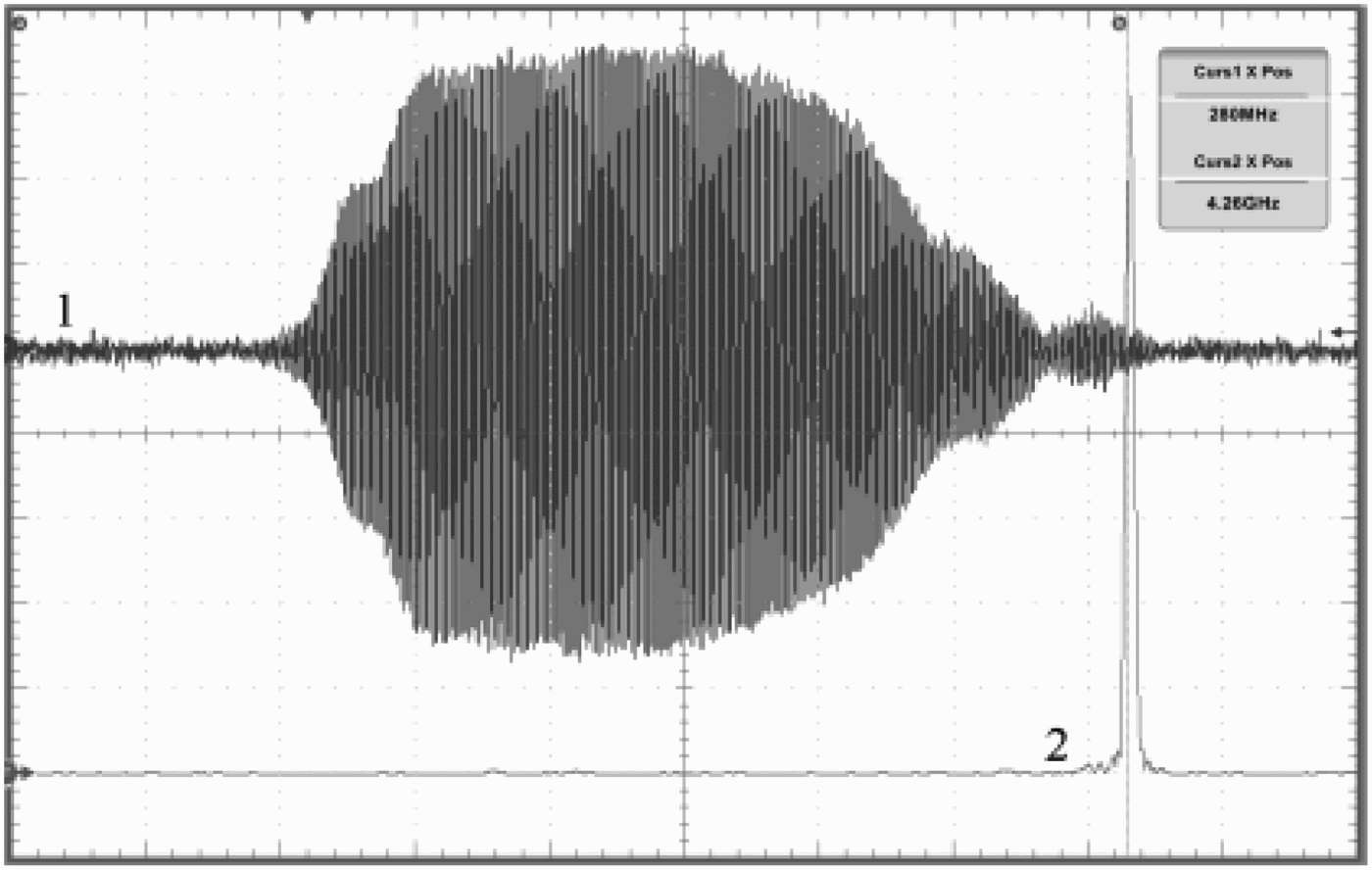
By using an oscilloscope with sampling rates of 50 Gs/s, the microwave was measured directly, as shown in Figure 13, and its spectrum demonstrates that the frequency is 4.26 GHz with a very narrow band. In addition, from the amplitude of the microwave signal in Figure 13, microwave power of 6.4 GW can be calculated, consistent with previous measurement results.

Fig. 13. Waveforms of microwave pulse (vertical scale, 400 mv/div; horizontal scale, 10 ns/div) (1) and its spectrum (480 MHz/div) (2).
The variations of microwave power and efficiency on diode voltage are shown in Figure 14. The efficiency exceeded 40% at a voltage range of 700–1030 kV. When the diode voltage was 820 kV, the output power was 4.4 GW with a maximum efficiency of 47% (Fig. 15). When the diode voltage amounted to 1.2 MV, the output power was up to 7.4 GW with pulse width of 31 ns. The diode current increased abruptly during the pulse duration, which may be caused by the emission of the cathode shank (Fig. 16).

Fig. 14. (Color online) Microwave power and efficiency versus diode voltage in the klystron-like RBWO.

Fig. 15. (Color online) Waveforms of the diode voltage (1), diode current (2), microwave detector signals through the online coupler (3) and in the radiation field (4) (diode voltage 820 kV, diode current 11.4 kA, microwave power 4.4 GW, 20 ns/div).

Fig. 16. (Color online) Waveforms of the diode voltage (1), diode current (2), microwave detector signals through the online coupler (3) and in the radiation field (4). (diode voltage 1.2 MV, diode current 18.7 kA, microwave power 7.4 GW, 20 ns/div).
When the modulation cavity and extraction cavity were removed, the variations of microwave power and efficiency with diode voltage were plotted in Figure 17. The highest efficiency was 24%, and the maximum power was only 2.7 GW, less than half of those obtained in the klystron-like RBWO.

Fig. 17. (Color online) Microwave power and efficiency versus diode voltage in the RBWO-RR.
DISCUSSIONS
In this section, a simple discussion about the power handling capacity and pulse shortening is provided. Simulation results show that the microwave duration increases with the diode voltage. When the diode voltage was 1 MV and microwave power was 6 GW, the microwave duration was about 42 ns, very close to the simulation duration. When the diode voltage was 1.1 MV and microwave power was about 6.5 GW, the microwave duration was 38 ns, which was about 10 ns less than the simulation result, and the pulse durations for the signals through the online coupler and in the radiation field were almost the same. When the diode voltage was 1.2 MV and microwave power was 7.4 GW, the microwave duration in radiation field was 31 ns, while that through online coupler was 42 ns with an irregularity at the back edge of the signal (Fig. 16), which could be explained by the reflection of microwave from dielectric window. From these results, we can conclude that the power handling capacity of the klystron-like RBWO was about 6 GW; after that, pulse shortening appeared in the klystron-like RBWO, and breakdown of the dielectric window began to occur when the power exceeded 6.5 GW.
To further increase the peak power and pulse duration, a series of measures will be adopted in the future. Previous experiments showed that increasing the collector radius from 4.4 cm to 4.5 cm lengthened the microwave duration for about 10 ns through reducing the plasma mainly resulted from the electron bombardment at the corner of the extraction cavity and the output waveguide. It is worth trying to further enlarge the radius of collector and to use the collector made of materials with low secondary electron emission yield. Experiment indicated that explosive emission emerged on the extraction cavity surface at the side close to SWS. A dual-cavity or multiple-cavity extractor is expected to decrease the electric field on the side wall of the extractor and enhance the microwave output power and pulse duration (Cao et al., Reference Cao, Zhang and He2009; Pasour et al., Reference Pasour, Smithe, Friedman and Phillips1999). Generally, surface treatment of the microwave-producing structures increases both the output power and pulse duration, which is attributed to induced outgassing and/or removal of micro-protrusions at the wall surfaces (Barker & Schamiloglu, Reference Barker and Schamiloglu2001). Surface treatment of the SWS and cavities will be used in our next experiments. Moreover, the breakdown threshold of the dielectric window should also be further increased (Barker & Schamiloglu, Reference Barker and Schamiloglu2001; Chang et al., Reference Chang, Liu, Tang, Chen, Shao and Huang2010c).
CONCLUSIONS
In conclusion, combining the transition radiation with Cerenkov radiation, a klystron-like RBWO has been put forward and studied theoretically and experimentally. In the device, the SWS is separated by a modulation cavity, which decreases the energy spread of the modulated beam electrons, and at the end of the SWS, an extraction cavity is added, which further recovers energy from the electron beam. Therefore, the efficiency of the klystron-like RBWO is increased significantly. Furthermore, the introduction of the TM021 resonant reflector and electrostatic insulation of the extraction cavity provided by the self-field of intense beam are beneficial for the increase of the power handling capacity. The experiment demonstrated stable generation of microwave with power of 6.5 GW at an efficiency of 36% and pulse duration of 38 ns, when the diode voltage was 1.1 MV, diode current was 16.4 kA, and the magnetic field was 2.2 T. When the diode voltage was 820 kV, efficiency up to 47% with microwave power 4.4 GW was also realized experimentally.