


Introduction
Ultrashort pulse X-ray radiation sources have become indispensable tools for a broad range of scientific disciplines, including physics, biology, materials science, chemistry, and medicine. The most common sources are synchrotrons, which are particularly useful because they produce high-quality X-ray beams to many users simultaneously. Current state-of-the-art sources are X-ray free-electron lasers (FELs), which operate on a similar principle to synchrotrons but produce X-ray beams via stimulated emission and which are coherent and can be very intense. FELs can generate ultrashort X-ray pulses of extremely high brightness, temporal coherence, and wavelength tunability and also provide a unique tool for probing matter with excellent spatial and temporal resolution. They are ideal for studying processes that occur on short timescales, such as, for example, the dynamics of chemical reactions and bio-molecular systems. The first FEL was reported in 1977 at long wavelengths (Deacon et al., Reference Deacon, Elias, Madey, Ramian, Schwettman and Smith1977) and now many FEL facilities exist worldwide (McNeil and Thompson, Reference McNeil and Thompson2010; Di Piazza et al., Reference Di Piazza, Müller, Hatsagortsyan and Keitel2012). Several operate (or are planned to operate) in the X-ray regime such as Linac Coherent Light Source (LCLS) at Stanford Linear Accelerator Center (SLAC) in the USA (Young et al., Reference Young, Kanter, Krässig, Li, March, Pratt, Santra, Southworth, Rohringer, DiMauro, Doumy, Roedig, Berrah, Fang, Hoener, Bucksbaum, Cryan, Ghimire, Glownia, Reis, Bozek, Bostedt and Messerschmidt2010), XFEL at DESY in Germany (Ayvazyan et al., Reference Ayvazyan, Baboi, Bohnet, Brinkmann, Castellano, Castro, Catani, Choroba, Cianchi, Dohlus, Edwards, Faatz, Fateev, Feldhaus, Flöttmann, Gamp, Garvey, Genz, Gerth, Gretchko, Grigoryan, Hahn, Hessler, Honkavaara, Hüning, Ischebeck, Jablonka, Kamps, Körfer, Krassilnikov, Krzywinski, Liepe, Liero, Limberg, Loos, Luong, Magne, Menzel, Michelato, Minty, Müller, Nölle, Novokhatski, Pagani, Peters, Pflüger, Piot, Plucinski, Rehlich, Reyzl, Richter, Rossbach, Saldin, Sandner, Schlarb, Schmidt, Schmüser, Schneider, Schneidmiller, Schreiber, Schreiber, Sertore, Setzer, Simrock, Sobierajski, Sonntag, Steeg, Stephan, Sytchev, Tiedtke, Tonutti, Treusch, Trines, Türke, Verzilov, Wanzenberg, Weiland, Weise, Wendt, Will, Wolff, Wittenburg, Yurkov and Zapfe2002), and SACLA in Japan (Tanaka et al., Reference Tanaka, Yabashi, Ishikawa, Aoyagi, Asaka, Asano, Azumi, Bizen, Ego, Fukami, Fukui, Furukawa, Goto, Hanaki, Hara, Hasegawa, Hatsui, Higashiya, Hirono, Hosoda, Ishii, Inagaki, Inubushi, Itoga, Joti, Kago, Kameshima, Kimura, Kirihara, Kiyomichi, Kobayashi, Kondo, Kudo, Maesaka, Marechal, Masuda, Matsubara, Matsumoto, Matsushita, Matsui, Nagasono, Nariyama, Ohashi, Ohata, Ohshima, Ono, Otake, Saji, Sakurai, Sato, Sawada, Seike, Shirasawa, Sugimoto, Suzuki, Takahashi, Takebe, Takeshita, Tamasaku, Tanaka, Tanaka, Tanaka, Togashi, Togawa, Tokuhisa, Tomizawa, Tono, Wu, Yabashi, Yamaga, Yamashita, Yanagida, Zhang, Shintake, Kitamura and Kumagai2012).
X-ray FELs are extremely useful for scientific research but are physically large structures with significant construction and operational costs. The size of present facilities, a kilometer or so in length, is determined by the particle accelerator that must produce high quality, multi-GeV electron beams on which FEL operation relies. Research access to these facilities is also limited due to the cost of operation, the limited number of beamlines and the small number of such facilities. Due to these limitations, there is a significant impetus for alternative approaches that could substantially reduce the size and cost of coherent high brightness X-ray sources. One such approach is to use electron beams produced by ultrashort pulse lasers instead of conventional particle accelerators. In particular, laser wakefield acceleration (LWFA) (Tajima and Dawson, Reference Tajima and Dawson1979) has demonstrated extremely high peak current, ultra-relativistic electron bunches from table-top scale systems (Faure et al., Reference Faure, Gilnec, Pukhov, Kiselev, Gordienko, Lefebvre, Rousseau, Burgy and Malka2004; Geddes et al., Reference Geddes, Toth, van Tilborg, Esarey, Schroeder, Bruhwiler, Nieter, Cary and Leemans2004; Mangles et al., Reference Mangles, Murphy, Najmudin, Thomas, Collier, Dangor, Foster, Divall, Gallacher, Hooker, Jaroszynski, Langley, Mori, Norreys, Tsung, Viskup, Walton and Krushelnick2004) which may lead to important applications in science (Kneip et al., Reference Kneip, McGuffey, Martins, Martins, Bellei, Chvykov, Dollar, Fonseca, Huntington, Kalintchenko, Maksimchuk, Mangles, Matsuoka, Nagel, Palmer, Schreiber, Ta Phuoc, Thomas, Yanovsky, Silva, Krushelnick and Najmudin2010) and technology (Mangles et al., Reference Mangles, Walton, Najmudin, Dangor, Krushelnick, Malka, Manclossi, Lopes, Carias, Mendes and Dorchies2006). This opens the possibility of constructing table-top X-ray FELs that are much smaller than conventional facilities and at a fraction of the cost. Such a step would be transformative in nature: such that research reserved exclusively for large-scale FELs could be potentially conducted on a mass scale in universities and research centers using small FELs driven by compact laser systems.
The first design concept for a tabletop, X-ray FEL, allowing for significant reduction in the undulator length, was proposed in 2007 (Eichner et al., Reference Eichner, Gruner, Becker, Fuchs, Habs, Weingartner, Schramm, Backe, Kunz and Lauth2007; Grüner et al., Reference Grüner, Becker, Schramm, Eichner, Fuchs, Weingartner, Habs, Meyer-ter-Vehn, Geissler, Ferrario, Serafini, van der Geer, Backe, Lauth and Reiche2007), in which the electron beam is driven by a petawatt short pulse laser. The precursor of coherent radiation, soft X-ray undulator radiation from laser-plasma-accelerated electron beams, was experimentally demonstrated 2 years later (Fuchs et al., Reference Fuchs, Weingartner, Popp, Major, Becker, Osterhoff, Cortrie, Zeitler, Hörlein, Tsakiris, Schramm, Rowlands-Rees, Hooker, Habs, Krausz, Karsch and Grüner2009). The design was later refined to accommodate some common difficulties such as large energy spread encountered in laser-based electron beam accelerators (Maier et al., Reference Maier, Meseck, Reiche, Schroeder, Seggebrock and Gruner2012). In Grüner's design, the undulator period was λu = 5 mm, about 1/5 that of SLAC and FLASH, and the undulator strength parameter was K = 0.5. The saturation length (effectively, the undulator length) for radiation in the vacuum—ultraviolet (VUV) (25 nm) was only 0.8 m, making it tabletop-scale. Another concept for such tabletop FEL was proposed previously in Nakajima (Reference Nakajima2008), albeit for wavelengths in the infrared region. A compact FEL undulator, just 1 m long, using an electron beam driven by short pulse laser has also been investigated by Schlenvoight et al. (Reference Schlenvoight, Haupt, Debus, Budde, Jäckell, Pfotenhauer, Schwoerer, Gallagher, Brunetti, Shanks, Wiggins and Jaroszynski2008). Two scenarios for realizing FELs from laser-driven plasma-based accelerators in the XUV and X-ray regime were most recently described by Corde et al. (Reference Corde, Ta Phuoc, Lambert, Fitour, Malka and Rousse2013). Both would use an electron beam with energy 1–5 GeV, duration 4 fs, narrow energy spread (~0.1%) and undulator length of 12–100 m, which is still not suitable for university scale laboratories.
As demonstrated by Grüner et al. (Reference Grüner, Becker, Schramm, Eichner, Fuchs, Weingartner, Habs, Meyer-ter-Vehn, Geissler, Ferrario, Serafini, van der Geer, Backe, Lauth and Reiche2007), Eichner et al. (Reference Eichner, Gruner, Becker, Fuchs, Habs, Weingartner, Schramm, Backe, Kunz and Lauth2007), Fuchs et al. (Reference Fuchs, Weingartner, Popp, Major, Becker, Osterhoff, Cortrie, Zeitler, Hörlein, Tsakiris, Schramm, Rowlands-Rees, Hooker, Habs, Krausz, Karsch and Grüner2009), Nakajima (Reference Nakajima2008), Schlenvoight et al. (Reference Schlenvoight, Haupt, Debus, Budde, Jäckell, Pfotenhauer, Schwoerer, Gallagher, Brunetti, Shanks, Wiggins and Jaroszynski2008), and Corde et al. (Reference Corde, Ta Phuoc, Lambert, Fitour, Malka and Rousse2013), miniaturizing FELs can be achieved by a reduction of the undulator period from the typical cm scale to the mm scale. Recently, development of an even shorter, sub-mm period (λu = 400 μm) “mini-undulator” has been reported using laser-micro-machined Sm-Co magnets (Peterson et al., Reference Peterson, Oniku, Patterson, Le Roy, Garraud, Herrault, Dempsey, Arnold and Allen2014). Figure 1 shows such a fabricated 50-period mini-undulator with a period of λu = 400 μm. The nominal field for this undulator, with a 200-μm air gap, is B = 0.2 T. The undulator period is 75 times smaller as compared with the undulator at SLAC (LCLS) and 12 times smaller than Gruner's. The reduction in λu is expected to shorten the undulator, bringing the prospects of meter-scale X-ray FELs closer to reality.
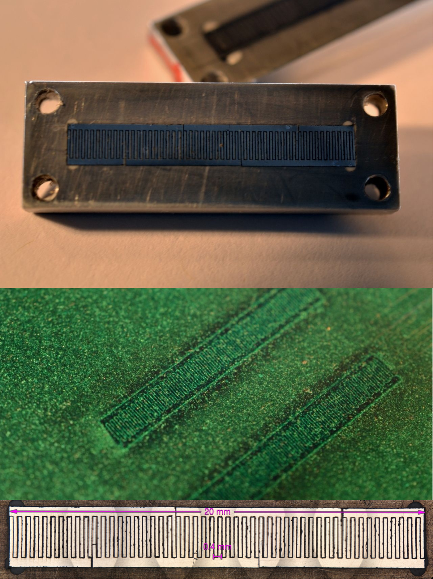
Fig. 1. Photographs of a mini-undulator with a 400-μm period from different views and a photograph of magnetic viewing paper placed over the magnet arrays showing the magnetic field variations.
In this paper, we study the radiation characteristics of a short pulse driven electron beam passing through this type of mini-undulator and explore the possibility of using it as an active media for a tabletop FEL. We consider a planar undulator with 2500 periods of λu = 400 μm, peak magnetic field B = 0.2 T, and strength parameter K = 7.5 × 10⁻³. The beam and undulator parameters are provided in Tables 1 and 2. For comparison, the corresponding parameters of an operational X-ray FEL, the LCLS (Huang and Kim, Reference Huang and Kim2007; Young et al., Reference Young, Kanter, Krässig, Li, March, Pratt, Santra, Southworth, Rohringer, DiMauro, Doumy, Roedig, Berrah, Fang, Hoener, Bucksbaum, Cryan, Ghimire, Glownia, Reis, Bozek, Bostedt and Messerschmidt2010) are also listed in Table 1.
Table 1. Electron beam and undulator parameters for the mini-undulator and LCLS-FEL

Table 2. Electron bunch parameters

We also describe preliminary experiments performed with this prototype undulator (although only with 50 periods) using the undulator in conjunction with a LWFA electron beam with an energy of up to 400 MeV. We show that the high energy components of the electron beam can be propagated cleanly and consistently through the undulator. The spectrum of X rays produced from the interaction is also measured, however, in these measurements using the short (50 periods) undulator, X-ray emission from the undulator could not be distinguished from that due to the broadband X-ray emission resulting from the electron beam interaction with the structure of the mini-undulator. It was found that there was an associated large divergence low energy (dark current) component to the electron beam (produced during the wakefield acceleration process) which caused a background bremsstrahlung source in the X-ray spectral region. Limitations of such experiments and future improvements to the experimental system are described.
Principle of operation of the FEL
In a FEL, a beam of high-energy (~GeV) electrons travels through a series of magnets (an undulator) that produces a periodic magnetic field. The gain process in a FEL results from the interaction of these relativistic electrons with either an external seed laser beam tuned to the undulator wavelength or the emitted synchrotron radiation from the electron beam itself. Most FELs operate using a scheme called self-amplified spontaneous emission (SASE). In a SASE-FEL, a long undulator amplifies the initial spontaneous radiation originating from the shot-noise fluctuations of the electron beam. As the beam of electrons passes through an undulator, the electrons move on sinusoidal trajectories and emit incoherent synchrotron radiation. This radiation interacts with the electrons and an energy exchange takes place. Some electrons gain energy and move to the front of the bunch, while others lose energy and drop behind. Thus, the interaction modulates the electron beam such that the electrons form micro-bunches separated by a distance equal to the undulator emission wavelength. The electrons in these micro-bunches are gradually set in phase, causing them to contribute coherently to the exponentially growing radiation field. After a certain distance, often tens of meters, coherent radiation can build up to significant levels. This lasing process is very sensitive and the requirements for an operational FEL are stringent: Both the injected electron beam and undulator must be of very high quality (especially for lasing at short wavelengths). Beams with extremely high current (tens of kiloamps), small emittance (1π mm mrad), large energy (~GeV) and small energy spread (0.1%) are required. An undulator of tens or hundreds of meters in length must be constructed with high precision, which is a significant engineering challenge.
An important feature of the FEL is its wavelength scalability. The fundamental wavelength of the FEL is given by:
 $${\rm \lambda} _{\rm f} = \displaystyle{{{\rm \lambda} _{\rm u}} \over {2{\rm \gamma} ^2}}\left( {1 + \displaystyle{{K^2} \over 2}} \right)$$
which is a function of the period length of the undulator field, λu, the undulator strength parameter, K and the electron beam energy γ (Lorentz factor). The wavelength can be tuned by varying either the electron beam or the undulator parameters. The latter is subject to engineering constraints and is usually fixed. Most commonly, the fundamental wavelength of the FEL is tuned by simply changing the beam energy, γ. According to Eq. (1), for an undulator with a small strength parameter, K <<1, and electron beam with energy in the range of hundreds of MeV to GeV, the FEL emits radiation in the X-ray regime.
The second parameter which plays a key role in the operation of the FEL is the Pierce parameter, which can be used to characterize several FEL properties such as conversion efficiency from the electron beam power into FEL radiation power, gain, and saturation length. In one-dimensional (1D) theory the Pierce parameter is defined as (Corde et al., Reference Corde, Ta Phuoc, Lambert, Fitour, Malka and Rousse2013);
 $${\rm \rho} = \displaystyle{1 \over {\rm \gamma}} \left( {\displaystyle{{A_{\rm u}{\rm \lambda}_{\rm u}} \over {4{\rm \lambda}_{\rm p}}}} \right)^{2/3}$$
where the coefficient A u is a function of the undulator strength parameter. In the limit K <<1 it becomes  $A_{\rm u} = K/\sqrt 2 $. The other parameter in (2) is the relativistic plasma wavelength λp = 2πc/ωp, where
  ${\rm \omega} _{\rm p} = \sqrt {n_{\rm e}e_0^2 /({\rm \varepsilon} _0m_{\rm e})} $ is the plasma frequency. The latter depends exclusively on the beam parameters, such as beam diameter, D charge, Q and duration, τ through the electron density in the bunch n e = ((4Q/e 0)/(πD 2cτ)) (c is the speed of light, e 0 is the electron charge and m e is the electron mass). The power gain length, L gain, which defines the exponential amplification of the radiation power along the undulator length
  $P(z)\sim \exp (z/L_{{\rm gain}})$, is given by,
 $$L_{{\rm gain}} = \displaystyle{{{\rm \lambda} _{\rm u}} \over {4{\rm \pi} \sqrt 3 {\rm \rho}}}. $$
After a certain distance, the exponentially increasing power levels off. Saturation is typically reached after about 20 gain lengths and is usually defined as L sat ≅ λu/ρ. The undulator length, L u is generally assumed to be comparable with the saturation length. Thus all relevant parameters of the FEL can be expressed through the Pierce parameter.
In the situation under examination here, we can specify the characteristic parameters. Inserting the mini-undulator parameters listed in Table 1 and the beam parameters given in Table 2, we can calculate the Pierce parameter, gain and saturation lengths of the FEL as a function of the beam energy:
 $${\rm \rho} = 5.3 \times 10^{-2}/{\rm \gamma} $$
 $$L_{{\rm gain}}[m] = 3.5 \times 10^{-4}{\rm \gamma} $$
 $$L_{{\rm sat}}[m]\cong 7.5 \times 10^{-4}{\rm \gamma}. $$
Eq. (4) allow one to make theoretical predictions and determine the range of operational parameters for the mini-undulator. First, we adopted a range of fundamental wavelengths, which, for the purpose of this study, comprised the VUV and soft X-ray regions. Specifically, we chose
 $$1 \lt {\rm \lambda} _{\rm f} \lt 100\,{\rm nm}$$
From Eq. (1), one can determine the range of beam energies γ that will generate radiation in this desired wavelength interval:
 $$45 \lt {\rm \gamma} \lt 450.$$
Using (6), we can now determine the range of each parameter in (4):
 $$1.2 \times 10^{-4} \lt {\rm \rho} \lt 1.2 \times 10^{-3}$$
 $$0.02 \lt L_{{\rm gain}} \lt 0.2\,{\rm m}$$
 $$0.34 \lt L_{{\rm sat}} \lt 3.4\,{\rm m}{\rm.} $$
According to Eq. (7c) the length of the mini-undulator-based FEL would be on the order of ~1 m, much shorter compared with conventional FELs, primarily due to its small undulator period. The beam energy (6) is achievable with contemporary laser systems (Kneip et al., Reference Kneip, McGuffey, Martins, Martins, Bellei, Chvykov, Dollar, Fonseca, Huntington, Kalintchenko, Maksimchuk, Mangles, Matsuoka, Nagel, Palmer, Schreiber, Ta Phuoc, Thomas, Yanovsky, Silva, Krushelnick and Najmudin2010), but the beam energy spread, which must be comparable with or smaller than the Pierce parameter remains a challenge.
Spontaneous synchrotron radiation from the mini-undulator: Numerical modeling
Before describing the collective, self-consistent FEL interaction, we first consider spontaneous radiation emission generated by the mini-undulator. Planar undulators create a sinusoidal magnetic field in one direction, leading to a wiggling trajectory in the perpendicular plane. The magnetic field strength is of the form  $\vec{B} = (0,B_0\cos (2{\rm \pi} z/{\rm \lambda} _{\rm u}),0)$ assuming a peak magnetic field of B 0 = 0.2 T. The undulator strength parameter is K = e 0λuB 0/(2πm ec) = 7.5 × 10⁻³. The propagation direction of the electron beam is along “z”. The relativistic factor, γ, is varied between 50 and 1000, corresponding to electron kinetic energies, ε = γm ec 2, between 25 and 500 MeV. The trajectory of an electron and the full radiation field emits in the undulator are obtained from the classical electrodynamics. The motion of electrons inside the undulator is described by a set of relativistic equations of motion
 $$\displaystyle{{d\vec{\,p}} \over {d{t}^{\prime}}} = -e_0\displaystyle{{\vec{\,p} \times \vec{B}} \over {m_{\rm e}{\rm \gamma}}} $$
 $$\vec{v} = \displaystyle{{\vec{\,p}/m_e} \over {\sqrt {1 + {\lpar {\vec{\,p}/m_{\rm e}c} \rpar }^2}}} $$
 $$\displaystyle{{d\bar{r}} \over {d{t}^{\prime}}} = \! \hskip-1pt{\rm \vec{\hskip2.4ptv}}$$
where  $\bar{r} = (x,y,z)$,
  $\vec{p} = (p_x,p_y,p_z)$ and
  $\vec{v} = (v_x,v_y,v_z)$ are the radius vector, relativistic momentum, and velocity of the electron, respectively. The radiation characteristics of synchrotron radiation are calculated using the well-known formula for the power radiated per unit solid angle (Jackson, Reference Jackson2001):
 $$\displaystyle{{dP({t}^{\prime})} \over {d{\rm \Omega}}} = \displaystyle{{e^2} \over {{(4{\rm \pi} )}^2{\rm \varepsilon} _0c}} \displaystyle {{{ \big [ { \hskip-2pt{ \vec{\hskip2pt n}} \times \big \{ {\big( \hskip-2pt{ \vec{\hskip2pt n}} - { \hskip-2pt{ \vec{\hskip2pt \rm \beta}} \big ) \times \mathop { \hskip-3pt { \vec{\hskip2.6pt \rm \beta}}} \limits \vskip1pt^^^ {\hskip-4pt \vskip-1.3pt {\scale60%\bullet}} } \big \} } \big ] }^2} \over {{\big ( {1-{ \hskip-2pt{ \vec{\hskip2pt n}} \cdot { \hskip-2pt{ \vec{\hskip2pt \rm \beta}}} \hskip1pt \big ) }^5}}$$
 In Eq. (9) t′ is the “retarded” time,  $\vec{n}$ is the direction of emitted radiation in solid angle dΩ and
  $ { \hskip-4pt{ \vec{\hskip3pt \rm \beta}} = \hskip-1.4pt\vec{\hskip1.4pt v}/c$ and
  $\! \mathop { \hskip-3pt { \vec{\hskip3pt \rm \beta}}} \limits \vskip1pt^^^ {\hskip-4pt \vskip-1.3pt {\scale60%\bullet}} \!$ are the electron velocity and acceleration (relative to c), respectively. The angular distribution is simply calculated on a series of small stretches of electron trajectory traversed between time t′ and t′ + Δt′. Time integration of (9) yields the synchrotron energy emitted per solid angle. Further integration over the polar angle θ and azimuthal angle φ yields the total radiated energy.
In the following, we assume that the mini-undulator and beam parameters are fixed except for the beam energy γ. Figure 2 plots the calculated characteristics of synchrotron radiation. The fundamental wavelength versus beam energy is given in Figure 2a. The energy radiated as synchrotron radiation increases, as expected, as γ 2 (Fig. 2b). It is in the nJ range, but since it only serves as seed radiation, which will be amplified along the length of the undulator, its particular magnitude is not important at this stage. The emission angle θ (full width at half maximum) relative to the direction of the beam is plotted in Figure 2c. Due to the small “K” parameter of the mini-undulator, the emission is azimuthally symmetric. Cylindrical symmetry around z is therefore assumed and only the distribution along angle θ is given. Another parameter of interest is the conversion efficiency of electron beam energy to radiation. Due to the small undulator parameter, only a small fraction of the beam energy is converted to radiation, of the order of 10−8–10−9.
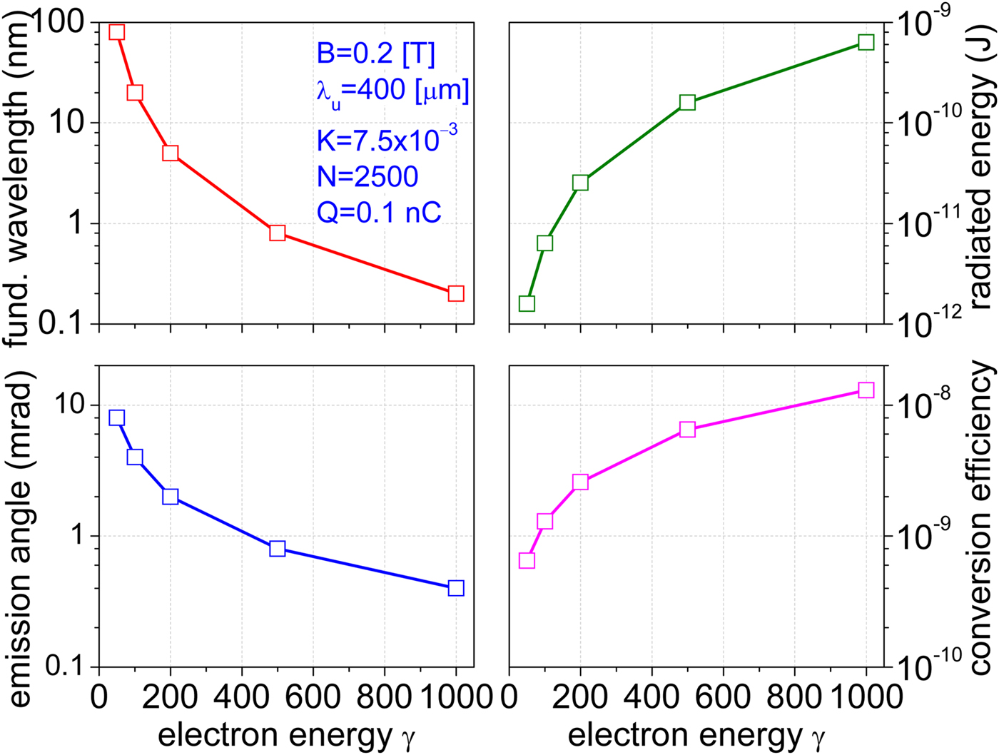
Fig. 2. Synchrotron radiation fundamental wavelength (a), radiated energy (b), emission angle [full width at half maximum (FWHM)] (c) and conversion efficiency of the electron beam to radiation (d) versus beam energy. Undulator parameters: Peak magnetic field B 0 = 0.2 T, period λu = 400 μm, strength parameter K = 7.5 × 10⁻³, number of periods N u = 2500, and length L u = 1 m.
FEL theory
The theoretical background of FELs is presented in numerous textbooks and papers (Bonifacio et al., Reference Bonifacio, Casagrande, Cerchioni, De Salvo Souza, Pierini and Piovella1990; Saldin et al., Reference Saldin, Schneidmiller and Yurkov2000; Huang and Kim, Reference Huang and Kim2007; Khan, Reference Khan2008) where 1D theory is used to describe the amplification process along the undulator length.
Low-gain FEL theory
We consider the case of a FEL amplifier in which the lasing process is initiated by seed radiation. The seed is an external coherent radiation source with wavelength, λℓ and the light wave co-propagating with the relativistic electron beam is a plane electromagnetic wave E x(z, t) = E 0 cos (k lz − ωlt + ψ 0) with wave vector, k l = ωl/c = 2π/λl. The wavelength of the seed radiation λl defines a resonant beam energy γ res determined from Eq. (1):  ${\rm \lambda} _{\rm l} = {\rm \lambda} _{\rm u}(1 + K^2/2)/(2{\rm \gamma} _{{\rm res}}^{\rm 2} )$. If the energy of the electron beam, γ is equal to the resonant energy, that is, γ = γ res, the net energy transfer from the ensemble of electrons to the light wave is zero. However, if the beam energy is (slightly) larger than the resonant beam energy, that is, γ>γ res, net energy transfer from the electron beam to the light wave along the undulator length is possible and the light wave is amplified. The FEL gain function (Khan, Reference Khan2008):
 $$G({\rm \eta} ) = -\displaystyle{{{\rm \pi} e_0^2 K^2N_{\rm u}^3 {\rm \lambda} _{\rm u}^{\rm 2} n_{\rm e}} \over {4{\rm \varepsilon} _0m_{\rm e}c^2{\rm \gamma} ^3}}\displaystyle{{\rm d} \over {{\rm dx}}}\left( {\displaystyle{{{\sin}^2x} \over {x^2}}} \right)$$
is defined as the relative energy increase of the light wave amplitude during one passage of the undulator. The dimensionless parameter x = 2πN uη, entering in the profile (sin (x)/x)2 of the gain function, is proportional to the number of undulator periods N u and the relative energy excess of the beam η = ((γ − γ res)/(γres)) >0. The normalized gain function I(x) = (d/(dx))((sin2x)/x 2) reaches the maximum I max ≅ 0.54 for x opt ≅ 1.3, from which the optimum “excess” beam energy ηopt = x opt/(2πN u) can be derived (ηopt ≅ 1 × 10⁻⁴ for N u = 2500) and the maximum value of the gain function determined: G max ≅ 2.5 × 10⁹/γ 3. Even for a relatively short undulator (L u = 1 m), a fairly large gain can, in principle, be achieved provided the energy spread of the beam is kept smaller than 1 × 10⁻⁴.
In low-gain theory, the gain is calculated in the linear regime by accounting only for the coupling of energy from the electromagnetic wave to the beam. The feedback, transfer of energy from the beam to the light wave is neglected. For this reason, the low-gain theory is not particularly useful since in practice all FEL's operate in the high-gain regime. In the next section, the high-gain theory will be briefly recalled and applied to model the mini-undulator.
High-gain FEL theory
In a high-gain FEL, there is a positive feedback process: The electrons emit radiation, which affects their position and sets them in phase causing them to emit with greater coherence. To describe the high-gain FEL interaction, a system of coupled equations that follow the electron motion and radiation generation self-consistently are required. The Lorentz equation describes the forces on each electron resulting from the combined undulator and radiation fields, and Maxwell's wave equation describes the envelope of the electric field of the radiation as driven by the transverse electron current. We restrict ourselves here to the 1D FEL theory where a dependency of the bunch charge density and the electromagnetic fields on the transverse coordinates is neglected. The electron bunches are assumed to be much longer as compared with the fundamental wavelength (L = cτ>>λf) and fringe effects occurring at both ends of the bunch are ignored. Diffraction of the light wave is disregarded as well. The influence of 3D effects and the associated limits of the 1D theory will be discussed later.
The complete set of self-consistently coupled first-order differential equations that describe the main physics of the high-gain FEL consists of four equations for the ponderomotive phase ψ i of electron i = 1, …N inside the bunch, normalized energy ηi = ((γ i − γ res)/(γ res)), amplitude of the light wave E x, and modulated transverse current density of electrons j 1 (Khan, Reference Khan2008; Schmuser et al., Reference Schmuser, Dohlus and Rossbach2008). Low-gain theory uses only the first two equations neglecting the growth of E x. Clearly, several simplifying assumptions have been made in deriving these equations. This system of coupled equations is restricted to uniform or periodic initial particle distributions. They are well suited for a simulation of the saturation process in a FEL amplifier seeded by monochromatic light, but a SASE-FEL cannot be modeled correctly because the initial particle distribution is random.
A series of 1D numerical simulations were performed with the bunch and undulator parameters listed in Tables 1 and 2. Figure 3 shows power amplification and saturation for three fundamental wavelengths, λf = 1, 10, and 100 nm. For each run the input beam energy above resonance was set equal to the corresponding Pierce parameter, that is, (Δγ i/γ res)z=0 ≅ ρ. Starting with a very low level of power at the entrance of the FEL, and after a short “lethargy” regime of about two gain lengths, the power increases exponentially until saturation. Saturation is reached when the density modulation is nearly complete. We verified that the choice of initial seed field (incident power) does not affect the final power saturation level. After reaching saturation, the radiated power oscillates, which is a commonly observed phenomenon. The gain and saturation lengths can be derived from each curve. For the shortest fundamental wavelength, λf = 1 nm, the simulations yield saturation length of ~3.5–4 m, while Eq. (4c) predicts saturation length L sat ≅ 3.3 m. For λf = 100 nm, the saturation length is only L sat ≅ 0.5 m. For intermediate wavelengths, 10–20 nm, the saturation length is 1–1.5 m. It is instructive to compare the mini-undulator to “standard” undulators (Grüner et al., Reference Grüner, Becker, Schramm, Eichner, Fuchs, Weingartner, Habs, Meyer-ter-Vehn, Geissler, Ferrario, Serafini, van der Geer, Backe, Lauth and Reiche2007; Eichner et al., Reference Eichner, Gruner, Becker, Fuchs, Habs, Weingartner, Schramm, Backe, Kunz and Lauth2007) for fundamental wavelengths in the VUV. For λf = 20 nm both yield comparable saturation length, L sat ≅ 1 m. The disadvantage of larger undulator periods considered in Grüner et al. (Reference Grüner, Becker, Schramm, Eichner, Fuchs, Weingartner, Habs, Meyer-ter-Vehn, Geissler, Ferrario, Serafini, van der Geer, Backe, Lauth and Reiche2007), and Eichner et al. (Reference Eichner, Gruner, Becker, Fuchs, Habs, Weingartner, Schramm, Backe, Kunz and Lauth2007), is offset by the larger “K” number. The gain and saturation lengths, derived from Figure 3, are in very good agreement with the analytical predictions of Eq. (7). Figure 3 also confirms the expected scaling of undulator length versus fundamental wavelength:
 $$L_{\rm u}\cong L_{{\rm sat}} \sim {\rm \gamma} \sim 1/ \sqrt {{\rm \lambda} _{\rm f}} $$
Fig. 3. Power amplification and FEL pulse energy as a function of the length z traveled in the undulator for beam energies γ = 450, 142 and 45, corresponding to fundamental wavelengths 1, 10 and 100 nm. The energy above resonance at the undulator entrance is η = (Δγ/γ res)z=0 = 10−4, 3 × 10⁻⁴, 10−3, respectively. Electron bunch parameters: Q = 0.1 nC, D = 20 µm, τ = 20 fs, I = 5 kA. Undulator parameters: λu = 400 μm, B 0 = 0.2 T and K = 7.5 × 10⁻³.
The range of fundamental wavelengths of interest (5) can be covered by an undulator which varies in length by one order of magnitude, from ~0.4 to ~4 m.
The simulation results presented above are based on the 1D theory, which is highly idealized. The limits of the 1D theory arise when considering the transverse dimensions, and for more realistic results one has to consider the so-called 3D effects (Grüner et al., Reference Grüner, Becker, Schramm, Eichner, Fuchs, Weingartner, Habs, Meyer-ter-Vehn, Geissler, Ferrario, Serafini, van der Geer, Backe, Lauth and Reiche2007; Corde et al., Reference Corde, Ta Phuoc, Lambert, Fitour, Malka and Rousse2013). Xie (Reference Xie2000) proposed simple formulas that allow these effects to be estimated. According to Xie, the actual gain length is longer compared with that predicted by the 1D theory. He defined a modified gain length
 $$L_{{\rm gain}}\to L_{{\rm gain}}^{{\rm M}{\rm. Xie}} = (1 + {\rm \Lambda} )L_{{\rm gain}}$$
and modified efficiency at saturation. Following Corde et al. (Reference Corde, Ta Phuoc, Lambert, Fitour, Malka and Rousse2013), the degradation parameter Λ is:
 $${\rm \Lambda} = 0.45{\rm \Lambda} _{\rm d}^{0.57} + 0.55{\rm \Lambda} _{\rm \varepsilon} ^{1.6} + 3{\rm \Lambda} _{\rm \gamma} ^2 $$
where Λd = ((L gainλf)/(4πσ 2)), Λε = 4π((ε2L gain)/(λfσ 2)) and  ${\rm \Lambda} _{\rm \gamma} = &InLnBrk; (1/ (\sqrt 3 {\rm \rho} )({\rm \Delta} {\rm \gamma} )/({\rm \gamma} _{{\rm res}}))$ are parameters taking into account diffraction, emittance, and energy spread effects, respectively (but they do not take into account space-charge effects). In the above formulas, σ = D/2 is the radius of the transverse distribution of the electron beam and ε is the un-normalized transverse beam emittance. These formulas show how 3D effects degrade the FEL performance, increasing the gain length and decreasing the efficiency. The 1D theory can be considered accurate if all three parameters are smaller than unity, that is,
 $${\rm \Lambda} _d,{\rm \Lambda} _{\rm \varepsilon}, {\rm \Lambda} _{\rm \gamma} \lt \lt 1.$$
In the opposite case of large degradation factor, Λ>>1, the saturation length increases. For this reason, the above formulas impose limitations on the beam and undulator parameters. Starting with Λd and applying the relevant numbers for λf = 100 nm (σ = 10 μm, γ = 450, L gain = 0.16 m), we get Λd ≅ 0.13. In the other extreme with λf = 100 nm (σ = 10 μm, γ = 45, L gain = 0.016 m), we get Λd ≅ 1.3. Overall, Λd ≅ 1, which is acceptable. The second condition, Λε<1, determines the maximum allowed beam emittance. It is fulfilled for normalized emittance εn = ε/γ = 0.1 − 0.3 μm rad, which imposes limitations on the angular spread of the beam. The third inequality, ((Δγ)/(γ res)) < ρ, leads to restrictions regarding the beam energy spread: ((Δγ)/(γ res)) <<10−3. The impact of Δγ/γ res was studied numerically using the 1D simulation code. If the maximum energy above resonance was less than the Pierce parameter, the saturation length was about the same and independent of Δγ/γ res as the one shown in Figure 3. However, in the opposite case, ((Δγ)/(γ res)) > ρ, the saturation length was found to increase with Δγ/γ res. Thus the energy above resonance (and hence, the energy spread) should not exceed the Pierce parameter.
Experimental tests on prototype mini-undulator
We then performed proof-of principle tests on a prototype of the mini-undulator (Fig. 1) which was the model for the calculations described in the previous section. This mini-undulator was constructed using laser machining of Sm-Co alloy and had a periodicity of 400 µm. The prototype was only 3 cm long (having 50 periods) and the B-field was 0.2 Tesla although the uniformity was less than required for actual FEL operation. Although experiments were conducted with this prototype, further developments in the technology may enable many more periods – with higher fields and more uniform field structures. In our case, experiments were conducted to investigate whether X-ray “undulator” radiation could be measured or whether other experimental issues might arise – since it was not expected FEL action would be possible due to available electron beam parameters from the LWFA used as well as the configuration of the prototype mini-undulator.
These experiments were performed using the LWFA experimental configuration at the Center for Ultrafast Optics at the University of Michigan to determine the issues involved with the simultaneous use of these two technologies. The experimental setup is shown in Figure 4. In this experiment, the Hercules laser was operated at about 100 TW and was focused into a helium gas jet to generate a plasma where a beam of electrons was accelerated to relativistic energies. The laser system produced a laser pulse with a duration of 30 fs and used Ti:Sapphire as the amplifying media so that the operational wavelength was centered at 800 nm. The mini-undulator was positioned about 5 cm after the interaction after a 25 µm thick aluminum foil to block X-ray emission from the interaction. Broadband X-rays from the interaction can be produced via “betatron” oscillations of the electron beam in the plasma wakefield, and which consequently also need to be blocked for measurements of undulator radiation. Although we have found previously that emission of betatron can be reduced through control of the laser pulse and plasma properties.
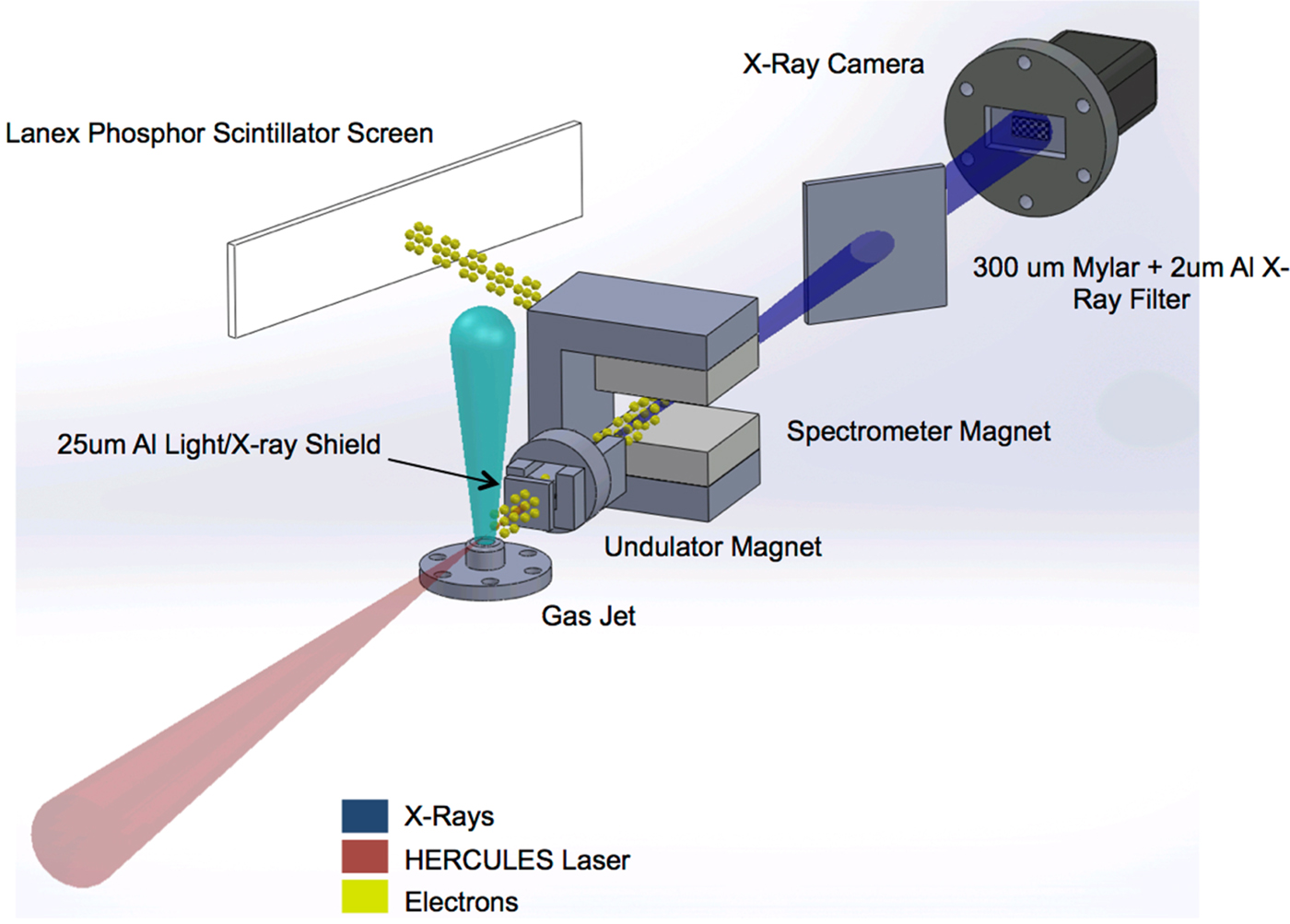
Fig. 4. Diagram of the set-up for preliminary measurements using the micro-undulator in a laser wakefield accelerator set-up.
In these experiments, electron beams at energies of up to 400 MeV were consistently generated. The gas jet target was operated at high pressure (~1019 cm−3) in order to maximize the charge produced in the electron beam. Issues of concern in these experiments were pointing instabilities of the electron beam from shot-to-shot, the self-emission from betatron emission as well as the bremsstrahlung produced as the electron beam is introduced into the mini-undulator and consequently hits the sides and the inner walls of the undulator.
In general, as observed in Figure 5 the high energy components of the electron beams generated in the experiment were able to pass through the undulator gap without much problem. There was some pointing instability – however, on most shots, there was little change in the high energy electron spectrum measured with/without the insertion of the mini-undulator. As an example the top two spectra in Figure 5 show the electron energy spectra of two successive shots without the undulator. The bottom data set show the electron beam spectra after passing through the undulator. It should be noted that in these experiments the electron spectrum was quite broad and extended to energies in excess of 300 MeV. The spectra were much too broad to enable free electron lasing. However, it was observed that there was no significant difference in the electron beam charge or spectrum passing through the undulator as opposed to that produced from the LWFA before traveling to the undulator. The differences observed in Figure 5 can be attributed to shot-to-shot fluctuations.
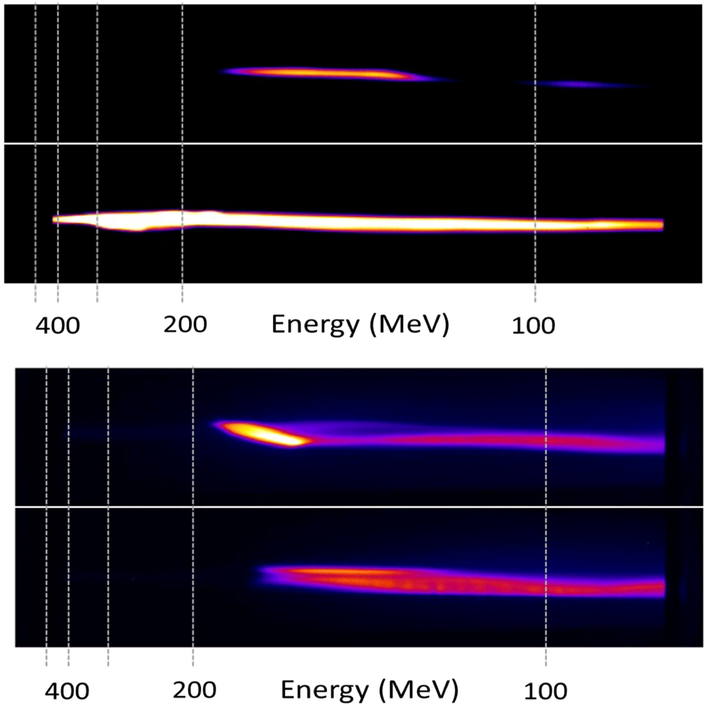
Fig. 5. Electron beam spectra taken without traveling through the undulator (top) and traveling through the undulator (bottom). Although the electron beam charge is slightly reduced after traveling through the undulator the spectral shape is similar. The change in beam charge is within shot-to-shot variability and we estimate that the majority of the electron beam from an LWFA is easily able to pass through an undulator of these dimensions.
In Figure 6 the measured X-ray spectrum is shown for three different conditions. In part (a) the undulator is moved to the side of the electron beam path so that it is not passing through the undulator. The background X-ray radiation observed in this case corresponds to the X rays produced via the betatron process in the laser wakefield accelerator, as well as contributions from X rays produced as the electron beam passes through the 25 µm thick aluminum foil.

Fig. 6. X-ray spectrum from the experiment under three different conditions (corresponding to the diagrams). The three conditions correspond to (a) the electron beam passing outside the undulator, (b) the electron beam traveling through the undulator, and (c) the electron beam striking the undulator material (generating) bremsstrahlung. Although there is a slight increase in the X-ray signal from the bremsstrahlung case the total photon spectrum in roughly similar. Further work showed that these X rays were mainly caused by a large divergence dark current in the beam.
In Figure 6b, however, the undulator was positioned on the axis of the electron beam so that the electron beam could pass through. The X-ray spectrum was then recorded and it was found (Fig. 6) that there was no significant difference in the X-ray spectrum observed. The conclusion was that bremsstralung from the Al filter or from the undulator itself makes a significant contribution to the final measured spectrum and that it was not possible to directly observe only undulator radiation because of the high levels of background radiation in the X-ray regime. This is further confirmed by positioning the undulator directly along the axis of the laser-driven electron beam. In this case, an X-ray spectrum in the range 2–20 keV was also recorded and showed no signatures of undulator radiation. Figure 7 shows the difference between the total X-ray flux with and without the undulator as a function of the peak energy of the LWFA electron beam. In Figure 7 there is no observed difference between the X-ray fluxes observed between these two cases.
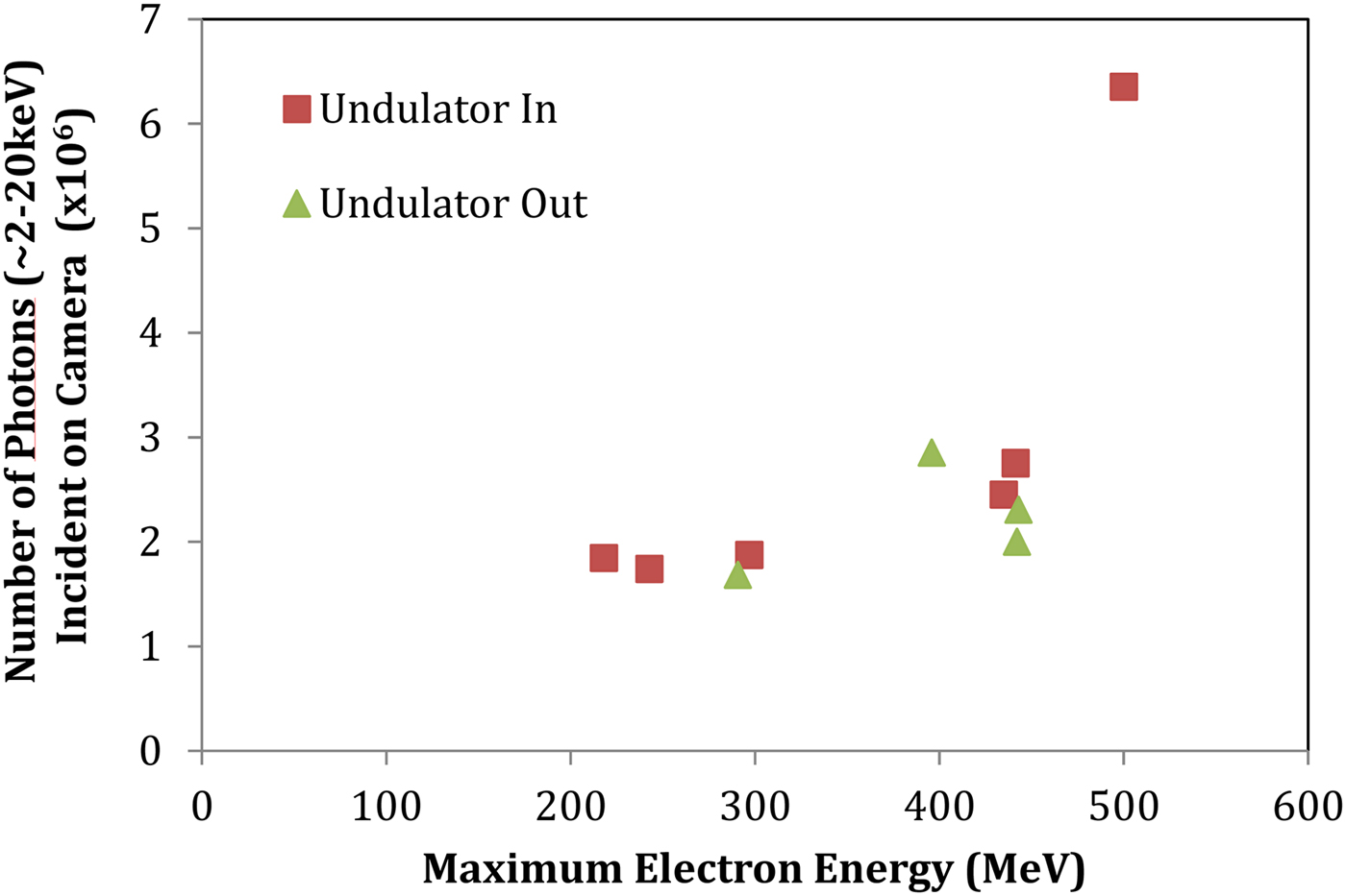
Fig. 7. Number of X-ray photons emitted versus peak electron beam energy with either the electron beam going through the micro-undulator or not.
In subsequent experiments, we measured the divergence of different energy components of the electron beam produced in these conditions. While the highest energy electrons were accelerated in a beam with a divergence <20 mrad – there was a large population of low energy electrons were emitted as a “halo” surrounding the most energetic beam. These electrons are less than 10 MeV but have a divergence >10° and consequently are a significant source of forward directed bremsstrahlung as they encounter solid material in the interaction chamber. Consequently, these experiments showed that there was a fairly large divergence beam of hard X rays and gamma rays associated with the laser wakefield which could not be suppressed in the experiments with the mini-undulator. In particular, there are a large number of energetic gamma rays produced (<1 MeV) which need to be blocked before undulator radiation can be measured in the X-ray regime.
The experiments generally showed that the micro-undulator could be successfully fielded with a laser-wakefield accelerator, however, the electron beam needs to be carefully controlled (perhaps with quadrupoles) to avoid interacting with the inner walls of the undulator and generating significant bremsstrahlung. In any case, to observe significant X-ray emission, our calculation in the previous section suggest that the length of the undulator in this situation needs to be many times longer than that of the proto-type used in these experiments.
Further work to measure and control the low energy halo of electrons surrounding the main LWFA electron beam is also underway.
Conclusions
An undulator with greatly reduced period and length and an electron beam driven by a short-pulse laser via LWFA were investigated as key components of a tabletop FEL. The characteristics of synchrotron radiation generated by the undulator were examined. The undulator was studied as a FEL amplifier in the low- and high-gain regimes. In the high-gain regime 1D numerical simulations were performed for electron beam energies ranging from 25 to 250 MeV. Gain lengths of 0.02–0.2 m and saturation lengths of 0.4–4 m were calculated for fundamental wavelengths between 1 and 100 nm. The calculated FEL peak power and pulse energy were 200 MW and 2 µJ, respectively. Lasing in the water window (2–4 nm) may be possible with a 2 m long undulator with improved electron beam properties. The impact of 3D effects and the constraints on the beam and undulator parameters were investigated. The study showed that undulators with a sub-mm period can successfully be used in table-top FELs, however, for generation of radiation in present experiments they need to be much longer than a few centimeters.
Experiments were also attempted using a LWFA. There are several important issues which must be addressed before very small undulators can be used in this configuration. In addition to the broad energy spread of the beam, we observed a very large divergence component of the electron beam (i.e., a low energy “halo” of electrons which surrounds the main beam). This population of electrons causes significant gamma-ray background and is difficult to suppress to enable systematic investigations of the mini-undulator configuration. It is likely necessary that focusing quadrupoles will be required – however, this will also generally increase the size of the system.
Acknowledgements
This work was supported by the US Defence Advanced Research Projects Agency (DARPA).


