INTRODUCTION
With the fast development of pulsed power technology (Liu et al., Reference Liu, Li, Zhang, Li and Wang2006, Reference Liu, Yin, Ge, Zhan, Chen, Feng, Shu, Zhang and Wang2007a, Reference Liu, Zhan, Zhang, Liu, Feng, Shu, Zhang and Wang2007b, Reference Liu, Zou, Wang, He and Zeng2008, Reference Liu, Cheng, Qian, Ge, Zhang and Wang2009; Mesyats et al., Reference Mesuats, Korovin, Gunin, Gubanov, Stepchenko, Grishin, Landl and Alekseenko2003; Yatsui et al., Reference Yatsui, Shimiya, Masugata, Shigeta and Shibata2005; Zou et al., Reference Zou, Liu, Zeng, Han, Yuan, Wang and Zhang2006) and intense electron beam generation from conventional accelerators (Li et al., Reference Li, Liu, Cheng, Chang, Wan and Wen2009a, Reference Li, Liu, Cheng, Xu, Ge and Wen2009b, Reference Li, Liu, Xu, Chen, Chang, Wan and Wen2009c), high-power microwave (HPM) techniques have achieved a significant progress and microwave radiation with GW level have been obtained in experiments (Eltchaninov et al., Reference Eltchaninov, Korovin, Rostov, Pegel, Mesyats, Rukin, Shpak, Yalandin and Ginzburg2003; Korovin et al., Reference Korovin, Kurkan, Loginov, Pegel, Polevin, Volkov and Zherlitsyn2003; Xiao et al., Reference Xiao, Zhang, Zhang, Li, Zhang, Song, Hu, Sun, Huo, Chen, Zhang and Liu2010). In pursuit of higher peak power and pulse energy, many new directions are becoming more and more attractive (Cao et al., Reference Cao, Zhang and He2009; Ge et al., Reference Ge, Zhong, Qian, Zhang, Gao, Jin, Fan and Yang2010; Li et al., Reference Li, Shu, Yuan, Zhu, Liu, Wang and Zhang2010; Zhang et al., Reference Zhang, Yuan and Liu2010; Zhu et al., Reference Zhu, Shu, Zhang, Li and Zhang2010). One of these directions is to develop devices capable of producing HPMs with a complicated spectrum (Ginzburg et al., Reference Ginzburg, Rozental’ and Sergeev2002). In combination with this, some HPM sources with two stable and separate frequencies have been investigated theoretically and experimentally in recent years (Chen et al., Reference Chen, Wang, Meng and Fan2009; Fan et al., Reference Fan, Zhong, Li, Shu, Zhang, Zhang, Zhang, Yang and Luo2007; Ju et al., Reference Ju, Fan, Zhong and Shu2009; Wang et al., Reference Wang, Zhang, Qian and Zhang2010, Reference Wang, Qian, Zhang, Zhang, Cao and Zhang2011; Zhang et al., Reference Zhang, Wang, Li, Liu, Qian and Zhang2008). Similar with the conventional circuit taxonomy, the existing dual-frequency sources could be divided into two types, named cascading and parallel structures, respectively.
In the cascading structure, a single beam is used to generate the dual-frequency HPMs (Chen et al., Reference Chen, Wang, Meng and Fan2009; Wang et al., Reference Wang, Zhang, Qian and Zhang2010). Such devices are generally of low beam-wave interaction efficiency due to the interference between the two HPM components with different frequencies. Simultaneously, the transportation of the microwave power generated in one section is greatly influenced by the other section, and thus the devices are probably of low power extraction efficiency. Therefore, there are many difficulties for the cascading structure to design the proper dynamic structure.
In the parallel structure, the beam-wave interaction regions for generation of dual-frequency HPMs are separated and two beams emitted by the same cathode are used to generate their respective microwave (Fan et al., Reference Fan, Zhong, Li, Shu, Zhang, Zhang, Zhang, Yang and Luo2007; Ju et al., Reference Ju, Fan, Zhong and Shu2009; Wang et al., Reference Wang, Zhang, Qian and Zhang2010, Reference Wang, Qian, Zhang, Zhang, Cao and Zhang2011; Zhang et al., Reference Zhang, Wang, Li, Liu, Qian and Zhang2008). However, such devices greatly depend on the design of the cathode distributing the beam currents. Besides, the microwaves with different frequencies are probably radiated at different time due to inconsistent excitation and saturation time. Because of independence of the HPMs generation, the design of the parallel structure is in essence consistent with the HPM source with single frequency.
Considering these reasons, it would be valuable to seek a HPM generator both with high output microwave power and simultaneous microwave radiation at dual frequencies. In this paper, a dual-frequency HPM generator based on transition radiation is put forward. The electromagnetic fields in the device are localized near the resonator cavities in the form of standing waves and thus the interference between the different HPM components with different frequencies is greatly degraded. Simultaneously, the time synchronism can be realized because the radiated microwaves are from a single electron beam with dual-frequency modulation. Owing to the coaxial structure, the new device also allows high input electric power and high output microwave power.
DESCRIPTION OF THE PRINCIPLE
Radiation Mechanism and Physical Model
The main varieties of microwave tubes are classified into three groups, according to the fundamental radiation mechanism involved: Cherenkov, transition, or bremsstrahlung radiation (Gold & Nusunovich, Reference Gold and Nusunovich1997). As is known, in microwave tubes based on transition radiation, the microwave fields are localized within the short-gap cavities (bunchers) and coherent radiation is produced by decelerating the electron bunches in the output cavity. Therefore, the fields in one buncher have a weak influence on the fields in the other buncher. An electron beam in turn modulated by two types of bunchers with different frequencies probably stimulates the dual-frequency HPMs in the vicinity of output cavity.
Figure 1a gives a three-dimensional general schematic of the designed dual-frequency HPM generator. Figure 1b is the corresponding simulation model, which is symmetric about the z-axis. As shown in the figures, the device mainly consists of five parts: an annular cathode, two sequent dual-cavity bunchers, respectively, corresponding to two different frequencies, a dual-cavity extractor, and a coaxial output structure. The resonance frequencies of the TM01 modes in the two bunchers mainly depend on the radial dimensions and can be given approximately by
and thus they can be chosen by adjusting the radii of the bunchers. The dual-cavity extractor includes two cavities to stimulate the respective microwaves. The first cavity has the same radial dimension with the buncher c (Fig. 1) and the second cavity has the same radial dimension with the buncher b (Fig. 1), respectively.

Fig. 1. (Color online) The three-dimensional schematic (a) and simulation model (b) of the designed dual-frequency high-power microwave generator. In figure (b), the characters a, b, c, d, and e represent the annular cathode, the first and second dual-cavity bunchers, the dual-cavity extractor, and the beam dump, respectively.
The basic principle of the proposed model is as follows. The annular electron beam emitted by the cathode transmits axially due to the restriction of the guiding magnetic field, and the velocity of electrons is modulated in succession by the electromagnetic fields with different frequencies when they pass through the two sequent bunchers. Finally, HPMs with two separate frequencies are simultaneously stimulated in the region of the dual-cavity extractor and extracted by the coaxial output structure. Compared with the exiting dual-frequency HPM generators, the designed device has the following merits: (1) The interference between the two HPM components with different frequencies is very weak because the fields are localized within the corresponding cavities. (2) The radiated microwaves are stimulated by the single modulated bunches in the vicinity of output cavity, and thus the time synchronism could be satisfied.
Correlation between Two Frequencies
Although the interference between the two bunchers with different frequencies is very weak, the previous bunches modulated by the first buncher is probably destroyed by the second buncher with the other operating frequency. Such a case could be improved by choosing two proper operating frequencies. Further analysis shows that the operating frequency in the second buncher should be multiple of the operating frequency in the first buncher.
Figure 2 denotes bunching of an electron beam at frequencies f and 2f. Obviously, the centers of bunches corresponding to frequency f is simultaneously located at the phase corresponding to zero or gain or absorption when the beam passes through the field with frequency 2f. Therefore, the latter would not destroy the previous bunches. Besides, the direct-current component of the beam can be modulated by the field at frequency 2f. Eventually, the dual frequency modulations of the electron beam are realized.

Fig. 2. (Color online) Process of beam bunching at frequency f and 2f.
Figure 3 describes the dispersion relations (Lemke, Reference Lemke1992), respectively, corresponding to two HPM components with different frequencies. In the figure, ω and β, respectively, denote the angular frequency and the mode wave number, and L 1 and L 2, respectively, represent the structure periods of the buncher b and buncher c (Fig. 1). The intersections of the beam line and the modes represent the working points of the dual-frequency HPM generator. From the figure, it is easy to yield

Fig. 3. (Color online) Dispersion relations corresponding to two different HPM components. Frequencies supported by the devices based on transition radiation are circled.
In case that the frequency f 2 is twice the frequency f 1, the structure period L 2 should be half of the structure period L 1.
SIMULATION RESULTS
Cold Test
Based on the above analyses, the main structure parameters are chosen as follows: r 1 = 1.2 cm, r 2 = 11.2 cm, r 3 = 3.0 cm, r 4 = 8.0 cm, r 5 = 3.8 cm, r 6 = 6.0 cm, L 1 = 8.0 cm, and L 2 = 4.0 cm (Fig. 1). According to Eq. (1), the operating frequencies for TM01 mode of the two bunchers are about 1.5 GHz (L-band) and 3.0 GHz (S-band), respectively. For the TM0n mode in the coaxial structure, the axial electric field E zn can be expressed as
where J n and Y n, respectively, represent the first and second kind Bessel functions with order n. In the coaxial drift-tube of inner radius r 5 and outer radius r 6, the field E zn satisfies the boundary conditions: E zn (r 5, z) = 0 and E zn (r 6, z) = 0. That is,
Combining the above two expressions gives
Setting n = 1 and substituting the given values into the above expression, the cut-off frequency of TM01 mode is about 6.87 GHz in the drift-tube. Therefore, the TM01 modes at L-band and S-band can be effectively cut off in the drift-tube.
Figure 4 shows the distributions of the electric fields corresponding to the two bunchers. The Eigen frequencies are 1.5 GHz and 3.2 GHz, respectively. Obviously, the two bunchers share a common radial area, where intense axial electric fields exist simultaneously and an electron beam is allowed to pass through. Figure 5 gives the radial profiles of the axial electric fields at the second cavity center of the L-band and S-band bunchers (corresponding to point 1 and point 2 in Fig. 1). As indicated in the figure, the axial fields can maintain high level in the channel of beam transportation and theoretically this is very advantageous to beam modulation. As a first approximation, the average radius of the electron beam would be that for which the axial electric fields are maximum. The practical location that electron beam passes through should be optimized in combination with the two bunchers.

Fig. 4. (Color online) Electric field distributions in (a) L-band buncher and (b) S-band buncher.

Fig. 5. (Color online) Radial profiles of eigen-fields in the L-band and S-band bunchers.
Figure 6 denotes that the L-band and S-band electromagnetic fields can be well localized in their respective buncher, which further verifies the independence of the two bunchers. Consequently, the interference between the different HPM components with different frequencies is greatly degraded.

Fig. 6. (Color online) Electric field distributions in the cascading L-band and S-band bunchers. (a) and (b) correspond to the L-band and S-band operating modes, respectively.
Hot Test
Last, the dual-frequency HPM generator is optimized with the particle-in-cell simulation code KARAT (Tarakanov, Reference Tarakanov1998). With an electron beam of 500 kV voltage and 15.0 kA current guided by a magnetic field of 0.8 Tesla, the main simulation results are given as follows.
The phase-space plot for the dual-frequency HPM generator is displayed in Figure 7, which illustrates the energy spread of the modulated beam electrons. It can be seen from this figure that the electron beam emitted by the cathode is accelerated in the diode region by the direct-current voltage, then in turn modulated by the electromagnetic fields in the L-band and S-band bunchers. Such an electron beam would stimulate the HPMs corresponding to the two bands in the vicinity of the dual-cavity extractor and be eventually collected by the beam dump.

Fig. 7. (Color online) Phase-space plot for the dual-frequency HPM generator.
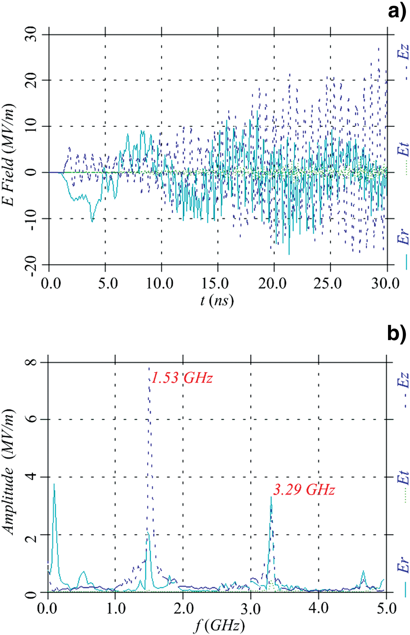
Figure 8 shows the variation of the electric fields versus time and corresponding frequency spectrum at point 1 (Fig. 1). This exhibits electromagnetic fields stimulated by the electron beam in the L-band buncher. The main frequency of the axial electric field modulating the beam is about 1.53 GHz, which is slightly greater than the Eigen frequency 1.5 GHz because of a loaded electron beam. Besides, the frequency of the second harmonic is close to the Eigen frequency of the S-band buncher and such a microwave component is probably helpful to stimulate the S-band microwave. As indicated in the figures, some unexpected modes also exist in the form of the transverse electromagnetic modes (TEM), which seem to be inevitable due to the coaxial inner conductor. However, the TEM modes cannot interact with the electron beam with axial velocity and thus they hardly influence the beam modulation.

Fig. 8. (Color online) Variation of electric fields versus time and corresponding frequency spectrum at point 1 (Fig. 1).
Figure 9 shows the variation of the electric fields versus time and corresponding frequency spectrum at point 2 (Fig. 1). Obviously, the electromagnetic fields are stimulated in the S-band buncher and the main frequency of the axial electric field is 3.29 GHz, which is approximately twice the frequency of the L-band microwave. As mentioned above, such a component would not destroy bunches modulated by the first buncher. Also, some unexpected TEM modes exist in the S-band buncher and they hardly have influence over the beam modulation.

Fig. 9. (Color online) Variation of electric fields versus time and corresponding frequency spectrum at point 2 (Fig. 1).
As shown in Figure 10, the radial structures of the axial electric fields in the L-band and S-band bunchers (point 1 and point 2 in Fig. 1) are basically in accordance with the results shown in Figure 5. That is to say, the operating modes are indeed the TM01 modes. Due to the loaded electron beam, the maximal values are partly shifted compared with the previous results (Fig. 5). However, in the actual beam path (r ≈ 5.0 cm), the modulating fields at both the L-band and the S-band still maintain high level. No obvious axial components are observed at point 3 (Fig. 1) and the electromagnetic fields exist in the coaxial output structure mainly in the form of TEM waves.

Fig. 10. (Color online) Radial profiles of modulating fields in the L-band and S-band bunchers.
Figure 11 shows the variation of the microwave power versus time and corresponding frequency spectrum at point 3 (Fig. 1). As shown in Figure 11a, a total average power of 1.60 GW is obtained in the coaxial output structure and the efficiency is about 21.3%. The corresponding spectrum is given in Figure 11b and the dominant frequencies are 1.53 GHz and 3.29 GHz, respectively. The spectrum indicates that the power level of the two bands is comparative. Besides, from the spectrum, we can also see that there exist some unexpected frequency components, especially the frequency about 100 MHz, which takes away a lot of energy. Such frequency components are probably stimulated in the process of beam voltage rise, corresponding to the time domain from about 3 ns to 10 ns in Figure 11a. Figure 12 gives the output power variation in the range from 20 ns to 30 ns and its corresponding frequency spectrum. Obviously, after the microwaves get to saturation, the unexpected frequency components are significantly degraded, and the total power of the output microwave is about 2.37 GW with dominant frequencies 1.53 GHz and 3.29 GHz.

Fig. 11. (Color online) Variation of the microwave power versus time and corresponding frequency spectrum at point 3 (Fig. 1).

Fig. 12. (Color online) Output power variation in the range from 20 ns to 30 ns and its corresponding frequency spectrum.
COMPARISON WITH OTHER DUAL-FREQUENCY DEVICES
Table 1 lists the recent simulation results of some existing dual-frequency HPM sources (Chen et al., Reference Chen, Wang, Meng and Fan2009; Fan et al., Reference Fan, Zhong, Li, Shu, Zhang, Zhang, Zhang, Yang and Luo2007; Ju et al., Reference Ju, Fan, Zhong and Shu2009; Wang et al., Reference Wang, Zhang, Qian and Zhang2010), including the proposed device in this paper. Due to higher input electric power, one can see clearly that the devices based on dual beams have higher output power level compared with the devices based on a single beam. However, as mentioned above, the two microwaves generated by the devices based on dual beams are probably radiated at different time because of inconsistent excitation and saturation time.
Table 1. Simulation results of some existing dual-frequency HPM devices

The really attractive dual-frequency HPM sources should be those devices allowing two microwaves simultaneous radiation. Obviously, the dual-frequency device based a single beam is more feasible to realize the time synchronism. However, as shown in Table 1, the power level of such devices is still dissatisfactory up to now. The proposed device in this paper possesses the highest power conversion efficiency compared with the other devices shown in the table. With almost the same input electric power, the output power of the proposed device is higher than that of the dual-frequency backward wave oscillator (BWO) based on dual beams (marked by superscript asterisk in Table 1). Even if the input power is only half of that of the magnetically insulated line oscillator (MILO) based on a single beam (marked by superscript plus sign in Table 1), the output power of the proposed device is still higher.
CONCLUSIONS
In this paper, a dual-frequency high-power microwave generator based on transition radiation is designed and investigated theoretically. In the device, the electromagnetic fields at different frequencies are localized in their respective buncher and thus the interference between the two wave bands is greatly degraded. Besides, the electromagnetic fields at different frequencies are radiated into the outer space by the same electron beam at the same time.
Further, the dual-frequency HPM generator is optimized with the particle-in-cell simulation code KARAT. With an electron beam of 500 keV and 15.0 kA guided by a magnetic field of 0.8 Tesla, an average power of 1.60 GW with a total power conversion efficiency of 21.3% is obtained and the frequencies are 1.53 GHz and 3.29 GHz, respectively. As indicated by the simulation results, the design of the dual-frequency HPM generator is feasible.
ACKNOWLEDGMENTS
This work was supported by the National Natural Science Fund of China (Grant No. 61171021) and the National High Technology Research and Development Program of China. The authors wish to express gratitude to Dr. Q. Zhang and Dr. G. X. Cheng for their discussions and help to revising the manuscript. The authors also acknowledge the editor and reviewers for their valuable comments and suggestions.