


Introduction
Treatment of head and neck tumours using radiotherapy requires highly accurate procedures,Reference Weltens, Kesteloot, Vandevelde and Van den Bogaert 1 as missing the treatment targets due to patient movements or lack of accuracy in positioning may lead to increased doses to some organs at risks (OAR) such as skin, spinal cord and the eyes.Reference Weltens, Kesteloot, Vandevelde and Van den Bogaert 1 , Reference Hess, Kortmann, Jany, Hamberger and Bamberg 2 Consequently, special thermoplastic head and neck immobilisation devices are used to reproducibly position the patient on the table for safe delivery of radiation.Reference Bahl, Ghosal, Kapoor, Bhattacharya and Sharma 3 Typically masks made of polyvinyl chloride (plastic) (PVC) or thermoplastic material such as Orfit masks (Orfit Industries America, Wijnegem, Belgium) are used as immobilisation systems for head fixation.
Intensity-modulated radiation therapy (IMRT) has proved to be effective for the treatment of nasopharyngeal cancers (NPC), with superior tumour coverage in comparison with all conventional techniques.Reference Radaideh and Matalqah 4 However, skin toxicity following IMRT treatment remains substantial due to the use of multiple tangential beams, consequently, skin dose measurements and skin-sparing techniques are highly recommended for head and neck treatments using IMRT.Reference Radaideh and Matalqah 4 It was found that IMRT increases skin doses by 19 and 27% with and without an immobilisation Klarity mask, respectively, when compared with conventional therapy.Reference Lee, Chuang and Quivey 5 previous studies found that the surface dose increased by thermoplastic immobilisation masks during IMRT.Reference Hadley 6 – Reference Póltorak, Fujak and Kukolowicz 9 Moreover, using some immobilisation devices may lead to increase skin surface dose between 16 and 27%.Reference Hadley 6 Other researchers found that using thermoplastic masks material (Klarity Medical & Equipment Co., Guangzhou, China) increased the surface dose from 10 to 42% for 6 MV and from 5 to 28% for 15 MV X-ray,Reference Póltorak, Fujak and Kukolowicz 9 while it increased the surface dose at anterior upper and lower neck for head and neck patient by 30% measured by film on anthropomorphic rando phantom.Reference Zhen, Nedzi, Chen, Jiang and Zhao 7 Another study concluded that head and neck mask increased surface dose by a factor of 3 using 18 MV and by a factor of 4 using 6 MV, and increasing in surface dose depends on the type of the mask, the size of the opening and the amount of stretching performed during the mask preparation.Reference Ali, Matthiesen and Algan 10 Therefore, increased skin doses using thermobilisation devices should be concern, as a bolus effect and contributing to skin toxicity.Reference Hess, Kortmann, Jany, Hamberger and Bamberg 2 , Reference Fiorino, Cattaneo and del Vecchio 11
Treatment planning system (TPS) may not give accurate doses for skin mainly due to excluding skin when considering OARs, during treatment planning.Reference Radaideh and Matalqah 4 , Reference Dogan and Glasgow 12 – Reference Chung, Jin and Dempsey 16 Inconsistencies between the calculated and measured doses, using IMRT, are the main motivation for the researchers to use skin dose measurements using dosimeters.Reference Chung, Jin and Dempsey 16 Therefore, it is necessary to measure the skin doses using dosimeter detectors such the metal–oxide–semiconductor field-effect transistor or thermoluminescence. Thermoluminescent dosimeters (TLDs) are widely used for in vivo dosimetry.Reference Lanson, Essers, Meijer, Minken, Uiterwaal and Mijnheer 17 – Reference Radaideh, Matalqah, Tajuddin, Lee, Bauk and Munem 22 The purpose of this work is to quantitatively evaluate the effect of thermoplastic Klarity Mask (Orfit Industries America, Wijnegem, Belgium) on patient skin dose during IMRT treatment.
Materials and Methods
In total, 99 chip-shaped LiF:Mg,Ti TLDs (Bicron NE, Waltham, MA, USA) were used after annealing and calibration cycles on the surface of a solid-water phantom and against a cylindrical ion chamber. Doses ranging from 0·05 to 1 Gy were delivered. The sensitivity and reproducibility of TLDs were selected within ±5% for calibration and measurement on the surface.Reference Radaideh and Matalqah 4 , Reference Radaideh, Matalqah, Tajuddin, Sabar and Abdel Munem 20 – Reference Radaideh, Matalqah, Tajuddin, Lee, Bauk and Munem 22 An anthropomorphic head and neck phantom was designed from 39 movable slices on which clinical organs were delineated (Figure 1).Reference Radaideh, Matalqah, Tajuddin, Fabian and Bauk 21 , Reference Radaideh, Matalqah, Tajuddin, Lee, Bauk and Munem 22 In addition, a cubic Perspex and a standard phantoms (Scanditronix Wellhőver) were used in this study (Figure 2). Phantoms were imaged by SIEMENS CT Scanner (SOMATOM Sensation Open, Medser-Heusenstamm, Germany), planned and irradiated using IMRT technique for 33 fractions, with 2·12 Gy per fraction. TLDs were readout and compared with the calculated doses obtained from TPS (Oncentra Maher plan V3.3). The correction factor was calculated for the anatomical Perspex phantom.Reference Radaideh, Matalqah, Tajuddin, Sabar and Abdel Munem 20
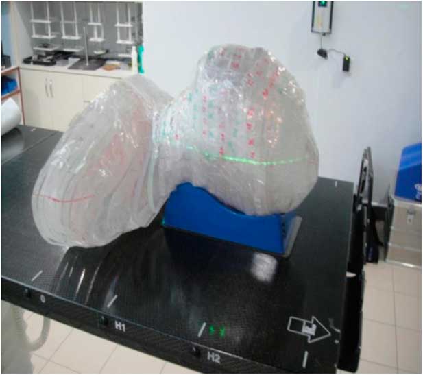
Figure 1 Fabricated anthropomorphic Perspex head and neck phantom for dosimetric verification of treatment delivery.

Figure 2 Head cube phantom (Scanditronix Wellhőver) and Perspex cube phantom.
Five NPC patients’ IMRT treatment plans were transferred consecutively with centre-points adjustment using computed tomography (CT) phantom images in a way that the OAR and planning target volume (PTV) for all plans were correctly matched (Figure 3). The anthropomorphic Perspex head and neck phantom was irradiated using the previous five plans with and without an immobilisation Klarity mask covering the head, neck and shoulder (Figure 4).
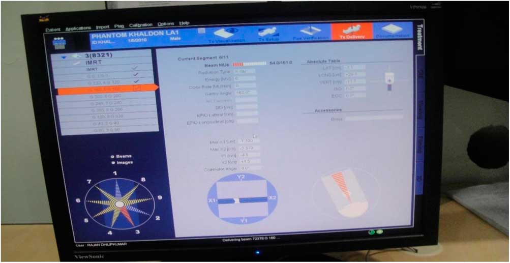
Figure 3 Intensity-modulated radiation therapy treatment planning for Perspex phantom delivered nine beams with 2.12 Gy per fraction.
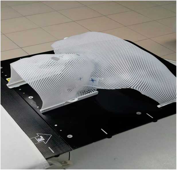
Figure 4 Immobilisation Klarity mask cover the phantom for head, neck and shoulder.
IMRT technique of 6 MV was used with a gross tumour volume receiving 70 Gy and clinical target volume receiving 60 Gy (the prescription goal was 95% of the PTV receives at least 70 Gy).Reference Henson, Eisbruch, D’Hondt and Ship 23 – Reference Li, Taylor, Ten Haken and Eisbruch 25 In total, eight TLDs were fixed on each target: right and left eyes, right and left buccal cavity, and right and left neck. An extreme caution was taken to maintain the detectors at the same locations for each patient plan. For each patient’s plan, three consecutive fractions were delivered with and without immobilisation Klarity mask and the average doses were considered.
Results
The reproducibility of the TLDs was checked and excellent consistency was obtained for repetitive measurements for each inter-fraction. The TLDs measurements displayed a linear dose response at the surface from 25 to 400 cGy. However, some measurements were performed outside the main field where the scattered photons had lower energy than the main beam energy.
Although designing the head and neck Perspex phantom, attention was given to the effect of phantom material (Perspex) on TLD readings. Three CT reference points and iso-centre were determined to match the points of standard and Perspex cubic phantoms. The measured doses of three IMRT fractions at different surface points of cubic and Perspex phantom are illustrated in Table 1. It was observed that the TPS overestimates the skin dose by 20·6% when compared with standard phantom and 22·1% as compared with Perspex phantom (Table 1). The deviation of inter-fraction of TLDs measurements was within the expected range of 18·36–19·67%. The variation between IMRT measured doses using standard phantom and Perspex phantom was within 4%.
Table 1 Comparison point doses between the average (AV.) of three intensity-modulated radiation therapy inter-fractions measured doses using standard and Perspex cube phantoms on the surfaces

Abbreviation: TPS, treatment planning system.
In total, 300 TLD measurements were used to estimate the skin doses at the six different reference points of head and neck patients with and without Klarity mask. The average variations between skin dose measurement without and with Klarity mask were 11·83, 11·23% at the left and right eyes, 10·26, 10·71% at the left and right buccal, and 9·36, 11·59% at the left and right neck, respectively (Table 2).
Table 2 Comparison point between average variation of measured skin dose for five patients plan at six regions between using a mask and without a mask
When TLDs doses at the phantom’s surface were compared with calculated dose, the TPS overestimates the skin doses with an average of 19·13% (Table 3). At eye regions, Klarity mask increased the doses by 10·1–12·9% at right eyes and 8·7–15·9% on the left eyes (Figures 5 and 6). In contrast, the calculated doses by TPS were higher than those measured by TLDs with Klarity mask by 17·7–20·25%. This study also showed that Klarity mask increased the dose at buccal region by 8·5–11·4% (Figures 7 and 8). These results are consistent with the results at the neck with 10·3–13·0% increase at right area and 7·5–11·9% at left area (Figures 9 and 10). TPS also overestimate the dose at neck regions by 17·7–22·1%.
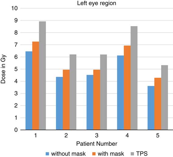
Figure 5 In vivo dose measurements at left eye regions and intensity-modulated radiation therapy treatment plan dose values for five patients. TPS, treatment planning system.
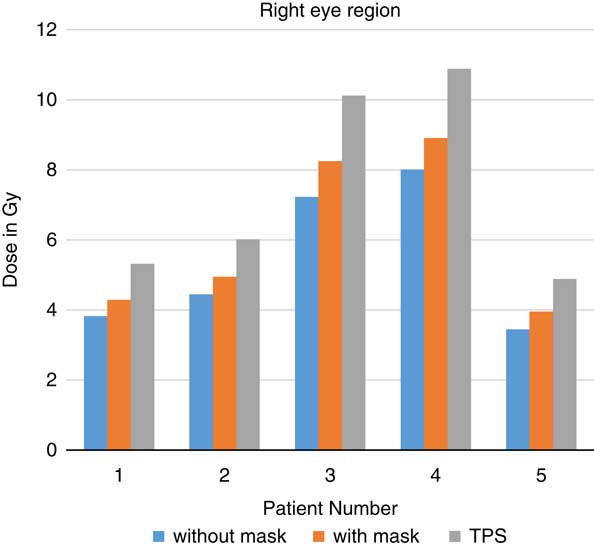
Figure 6 In vivo dose measurements at right eye regions and intensity-modulated radiation therapy treatment plan dose values for five patients. TPS, treatment planning system.
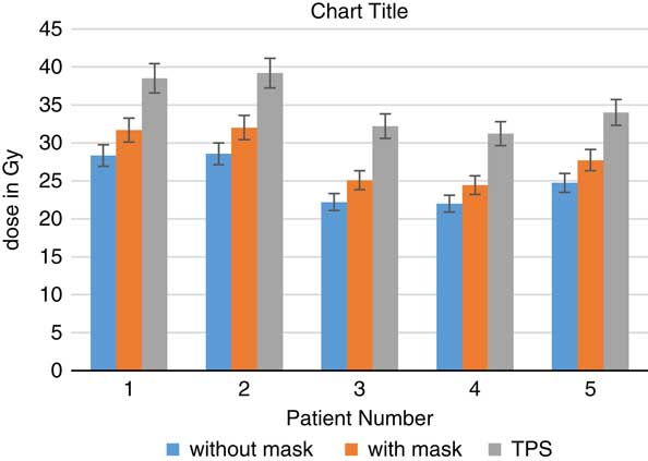
Figure 7 In vivo dose measurements at right buccal regions and intensity-modulated radiation therapy treatment plan dose values for five patients. TPS, treatment planning system.
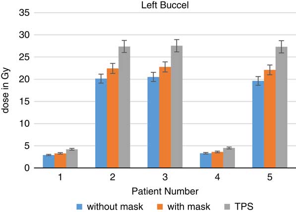
Figure 8 In vivo dose measurements at left buccal regions and intensity-modulated radiation therapy treatment plan dose values for five patients. TPS, treatment planning system.
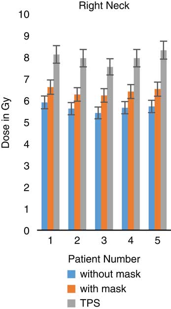
Figure 9 In vivo dose measurements at right neck regions and intensity-modulated radiation therapy treatment plan dose values for five patients. TPS, treatment planning system.
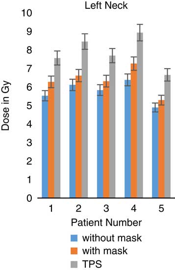
Figure 10 In vivo dose measurements at left neck regions and intensity-modulated radiation therapy treatment plan dose values for five patients. TPS, treatment planning system.
Table 3 In vivo average (av.) of three fractions skin dose measurements and intensity-modulated radiation therapy treatment plan dose values for five patients transfer plans on the phantom at different head and neck surface regions

Abbreviations: TLD, thermoluminescent dosimeters; TPS, treatment planning system.
Discussion
The phantom material can be a source of error during dosimetry measurements, therefore, a Correction Factor (K correction) for Perspex material was considered. In previous literature, the correction factor at 6 MV was found to be about 1·068 using TLDs and 1·063 using Monte Carlo simulation,Reference Lee, Yeh, Hsu, Shi, Chen and Wang 26 it was calculated in this study and was 1·0500±0·003. This correction replaces all errors resulting from a variation in sensitivity, phantom material, field size and fading. By multiplying the absorbed dose measured by TLDs in the Perspex phantom with the dose correction factor, the absorbed dose in the water phantom at the calibration depth can be obtained. However, the energy response of TLD-100 to a photon energy higher than 1 MV remained constant with negligible energy dependence.Reference Court, Tishler, Allen, Xiang, Makrigiorgos and Chin 13 , Reference Panettieri, Barsoum, Westermark, Brualla and Lax 15
After TLDs were irradiated for six times, the TLDs reproducibility ranged between 1 and 3·5% and with sensitivity <8% were used in this study. In agreement with another study, the standard deviations of TLD-100 reproducibility response were 3–5% of delivered doses ranging from 1 to 5 Gy.Reference Harris, Elson, Lamba and Foster 27 There is a linear relationship (R 2=0·998) between TLDs doses and measured doses at doses ranging from 0·5 to 4 Gy when measured at the surface. No energy correction factors were used as the reproducibility of TLDs had a SD <3·5%.
TPS overestimates the skin dose by 20·6% when compared with standard phantom and 22·1% as compared with Perspex phantom (Table 1). These results were in agreement with previous literatures where TPS overestimated prescribed doses by 25%.Reference Dogan and Glasgow 12 , Reference Court, Tishler, Allen, Xiang, Makrigiorgos and Chin 13 , Reference Panettieri, Barsoum, Westermark, Brualla and Lax 15 , Reference Chung, Jin and Dempsey 16 , Reference Kinhikar, Murthy, Goel, Tambe, Dhote and Deshpande 28 The main causes of this variation between in vivo measurements and TPS doses may be due to high dose gradients, set up error, the positioning of the patient and region of labelling dosimeters.Reference Chuang, Verhey and Xia 29 To avoid these errors, an extreme caution was taken to keep the same location of the detectors for each patients’ plan before treatment.
The study was planned so that 95% should be delivered at PTV, and other OARs were avoided. Fractionation of the total plan dose for multiple sessions can reduce skin erythema, however, the effect of radiation tends to be accumulative.Reference Koenig, Wolff, Mettler and Wagner 30 The severity of skin erythema is obviously related to the total accumulative dose and it becomes serious after exceeding the threshold dose.Reference Radaideh and Matalqah 4 , Reference Lee, Chuang and Quivey 5 After conducting all fractions of treatments, all patients have skin toxicity especially in the neck area, ranging from minor to major. Skin burn was obvious at the neck region and become severe after accumulative doses of 9% of the total 70 Gy (6·3 Gy) which is consistent with previous literature which found that the erythema occurred at skin dose after a dose of 6–8 Gy.Reference Mettler, Koenig, Wagner and Kelsey 31 A high correlation was found between the accumulative skin dose and skin toxicity.Reference Bahl, Ghosal, Kapoor, Bhattacharya and Sharma 3
Furthermore, such skin dose could be increased up to 57·1–88% in case of using a thermoplastic mask.Reference Amiel Halm, Tamri, Bridier, Wibault and Eschwège 8 The results of this study are consistent with this previous study and showed that skin dose increased when using thermoplastic masks material by 10–42% for 6 MV and by 5–28% for 15 MV photons using an ionisation chamber.Reference Póltorak, Fujak and Kukolowicz 9 The results of this study are consistent with this previous study and showed that head and neck Klarity mask increases skin dose by an average of 10·83% and the percentage depends on materials used (Table 2). In conclusion, Klarity mask is still acceptable immobilisation device when compared with other masks that increase the skin doses by about 14·8% (11·4–58·4%)Reference Zhen, Nedzi, Chen, Jiang and Zhao 7 and 16–27% for other immobilisation devices.Reference Hadley 32
Conclusion
In vivo dosimetry is a useful tool with IMRT techniques for areas where a high skin doses is expected, as the TPS may not give accurate dose values at the surface. Multiple factors may contribute to causing acute skin reaction for head and neck cancer patients, such as immobilisation contouring plane and IMRT technique. Klarity mask, used for patient immobilisation, increase surface dose by 10·83% more than that without the mask. However, the skin reaction and the surface dose measurements should be monitored, and must be taken into account.
Limitations
The researchers tried to keep TLDs at the same positions for all patients, however there may be slight deviation from the correct position.
Acknowledgements
The author gratefully acknowledge Qassim University, represented by the Deanship of Scientific Research, on the material support for this research under the number 1339-Cams1-12-1-2016-S-1240 during the academic year 1438 AH/2016 AD.
Conflicts of Interest
The author declare that there are no conflicts interest.


