


1 Introduction
One of the most serious tasks to be tackled on the way towards achieving controlled thermonuclear fusion in tokamaks is the prevention or suppression of instabilities related to magnetic reconnection processes. The latter deteriorate the plasma confinement properties and eventually destroy the equilibrium configuration. A very promising technique of counteracting these unstable magnetohydrodynamic (MHD) perturbations is based on the absorption of radiofrequency (rf) waves at the electron cyclotron frequency to drive a highly localized current on the magnetic surfaces where the perturbations grow (Fisch & Boozer Reference Fisch and Boozer1980; Perkins et al.
Reference Perkins, Harvey, Makowski and Rosenbluth1997). Significant technical progress has been made in recent years in the efficient generation of current with high power electron cyclotron (EC) wave beams, with the necessary characteristics of focussing and sharpness of the deposition. Similarly, control systems are rapidly progressing towards robust performance as has been recently demonstrated in experiments (Maraschek Reference Maraschek2012; Koleman et al.
Reference Koleman, Welander, La Haye, Eidities, Humphreys, Lohr, Noraky, Penaflor, Prater and Turco2014) and simulations (Fevrier et al.
Reference Fevrier, Maget, Lutjens and Beyer2017). The delivery of large, localized power to the system may however give rise to parasitic processes such as the possible onset of smaller scale structures in a non-constant flux
 $\unicode[STIX]{x1D713}$
regime (Comisso et al.
Reference Comisso, Lingam, Huang and Bhattacharjee2016), which may blur detection and hinder the feedback stabilization action. It should be noted that the present problem does not concern some other non-inductive currents methods of magnetic island control such as lower hybrid current drive (LHCD) (Reiman Reference Reiman1983), because the latter can only drive a broad current profile larger than a typical island width.
$\unicode[STIX]{x1D713}$
regime (Comisso et al.
Reference Comisso, Lingam, Huang and Bhattacharjee2016), which may blur detection and hinder the feedback stabilization action. It should be noted that the present problem does not concern some other non-inductive currents methods of magnetic island control such as lower hybrid current drive (LHCD) (Reiman Reference Reiman1983), because the latter can only drive a broad current profile larger than a typical island width.
A critical aspect of the electron cyclotron current drive (ECCD) technique is related to the deposition depth,
 $\unicode[STIX]{x1D6FF}_{\text{CD}}$
. A high focusing on the rational surface where the magnetic island develops is desirable to counteract efficiently the unstable reconnection process (Hegna & Callen Reference Hegna and Callen1997; Perkins et al.
Reference Perkins, Harvey, Makowski and Rosenbluth1997; Welander et al.
Reference Welander, Kolemen, La Haye, Eidietis, Humphreys, Lohr, Noraky, Penaflor, Prater and Turco2013; Rapson et al.
Reference Rapson, Fischer, Giannone, Maraschek, Reich and Treutterer2017; Park et al.
Reference Park, Na, Seo, Kim and Kim2018). Experimental success in control has been associated with feedback techniques based on accurate phase tracking, while a blind modulation is expected to induce a loss of control (Monticello, White & Rosenbluth Reference Monticello, White and Rosenbluth1978). These expectations are consistent with the assumptions of the Rutherford regime of evolution of a magnetic island (Lazzaro et al.
Reference Lazzaro, Borgogno, Brunetti and Comisso2018), where an island is almost ‘self similarly’ squeezed, without topological changes. However an increasing understanding of the fast spontaneous reconnection processes in other contexts (Comisso, Grasso & Waelbroeck Reference Comisso, Grasso and Waelbroeck2015) motivate a theoretical exploration of effects which might occur with high power density injection, considering the non-constant
$\unicode[STIX]{x1D6FF}_{\text{CD}}$
. A high focusing on the rational surface where the magnetic island develops is desirable to counteract efficiently the unstable reconnection process (Hegna & Callen Reference Hegna and Callen1997; Perkins et al.
Reference Perkins, Harvey, Makowski and Rosenbluth1997; Welander et al.
Reference Welander, Kolemen, La Haye, Eidietis, Humphreys, Lohr, Noraky, Penaflor, Prater and Turco2013; Rapson et al.
Reference Rapson, Fischer, Giannone, Maraschek, Reich and Treutterer2017; Park et al.
Reference Park, Na, Seo, Kim and Kim2018). Experimental success in control has been associated with feedback techniques based on accurate phase tracking, while a blind modulation is expected to induce a loss of control (Monticello, White & Rosenbluth Reference Monticello, White and Rosenbluth1978). These expectations are consistent with the assumptions of the Rutherford regime of evolution of a magnetic island (Lazzaro et al.
Reference Lazzaro, Borgogno, Brunetti and Comisso2018), where an island is almost ‘self similarly’ squeezed, without topological changes. However an increasing understanding of the fast spontaneous reconnection processes in other contexts (Comisso, Grasso & Waelbroeck Reference Comisso, Grasso and Waelbroeck2015) motivate a theoretical exploration of effects which might occur with high power density injection, considering the non-constant
 $\unicode[STIX]{x1D713}$
regime. The new aspect that must be considered is related to secondary instabilities that may develop during the control itself. Recently it has been shown (Lazzaro et al.
Reference Lazzaro, Borgogno, Brunetti and Comisso2018), in a series of numerical experiments examining the response to the rf driven current of a magnetic island induced by a reconnection event, that the control current has significant effects on the magnetic topology of the final stationary state as compared to the initial one and that these effects are directly related to the beam width. Secondary instabilities, plasmoid-like (Lazzaro et al.
Reference Lazzaro, Borgogno, Brunetti and Comisso2018) or triple tearing modes (Wang, Ma & Zhang Reference Wang, Ma and Zhang2016), may develop when an intense driven current has a deposition depth
$\unicode[STIX]{x1D713}$
regime. The new aspect that must be considered is related to secondary instabilities that may develop during the control itself. Recently it has been shown (Lazzaro et al.
Reference Lazzaro, Borgogno, Brunetti and Comisso2018), in a series of numerical experiments examining the response to the rf driven current of a magnetic island induced by a reconnection event, that the control current has significant effects on the magnetic topology of the final stationary state as compared to the initial one and that these effects are directly related to the beam width. Secondary instabilities, plasmoid-like (Lazzaro et al.
Reference Lazzaro, Borgogno, Brunetti and Comisso2018) or triple tearing modes (Wang, Ma & Zhang Reference Wang, Ma and Zhang2016), may develop when an intense driven current has a deposition depth
 $\unicode[STIX]{x1D6FF}_{\text{CD}}$
narrower than the magnetic island separatrix.
$\unicode[STIX]{x1D6FF}_{\text{CD}}$
narrower than the magnetic island separatrix.
In this paper we focus our attention on the theoretical possibility that the injected current drives the system into regimes where narrow current sheets may lead to the development of secondary instabilities, that could limit the efficiency of the control strategy by destroying the Rutherford topology of a magnetic island with a single
 $O$
-point. Therefore an appropriate feedback should ensure that the rf source suppresses the perturbation even in the case of a fast topological change with secondary structures, and a continuous or intermittent rf injection could be suited to produce an average stabilizing effect. Interestingly, recent experiments and numerical simulations (Felici et al.
Reference Felici, Goodman, Sauter, Cnala, Coda, Duval and Rossel2012; Fevrier et al.
Reference Fevrier, Maget, Lutjens and Beyer2017) with ‘sweeping’ rf injection demonstrate a technique that can overcome the problems analysed in the present work.
$O$
-point. Therefore an appropriate feedback should ensure that the rf source suppresses the perturbation even in the case of a fast topological change with secondary structures, and a continuous or intermittent rf injection could be suited to produce an average stabilizing effect. Interestingly, recent experiments and numerical simulations (Felici et al.
Reference Felici, Goodman, Sauter, Cnala, Coda, Duval and Rossel2012; Fevrier et al.
Reference Fevrier, Maget, Lutjens and Beyer2017) with ‘sweeping’ rf injection demonstrate a technique that can overcome the problems analysed in the present work.
In order to gain a basic understanding of this problem we consider a simple visco-resistive MHD regime, which allows us to carry out analytic calculations adopting the point of view of a converse of the Taylor problem of forced reconnection (Hahm & Kulsrud Reference Hahm and Kulsrud1985; Comisso et al. Reference Comisso, Grasso and Waelbroeck2015). Following this approach we derive an analytic expression for the threshold value of the ratio of the injected current amplitude over the deposition width below which the final stationary controlled state undergoes a secondary plasmoid-like instability phase.
The paper is organized as follows. Section 2 presents the model equations. The converse of the forced reconnection problem is analysed in § 3, where an analytical expression for the ratio of the deposition depth and the injected current peak below which the control current may lead to a current sheet instability is derived. We will see that the presence of viscosity relax this constraint. Finally, numerical simulations are presented in § 4, before our conclusions.
2 Model equations
We consider a plasma described by the two-dimensional reduced MHD model (Strauss Reference Strauss1976). Within this description the magnetic and the velocity fields can be written by means of the flux function
 $\unicode[STIX]{x1D713}$
and the stream function
$\unicode[STIX]{x1D713}$
and the stream function
 $\unicode[STIX]{x1D711}$
as
$\unicode[STIX]{x1D711}$
as
 $$\begin{eqnarray}\displaystyle & \displaystyle \boldsymbol{B}(x,y,t)=B_{z}\boldsymbol{e}_{z}+\unicode[STIX]{x1D735}\unicode[STIX]{x1D713}(x,y,t)\times \boldsymbol{e}_{z} & \displaystyle\end{eqnarray}$$
 $$\begin{eqnarray}\displaystyle & \displaystyle \boldsymbol{v}(x,y,t)=-\unicode[STIX]{x1D735}\unicode[STIX]{x1D711}(x,y,t)\times \boldsymbol{e}_{z}, & \displaystyle\end{eqnarray}$$
where
 $\boldsymbol{B}$
and
$\boldsymbol{B}$
and
 $\boldsymbol{v}$
indicate the magnetic and velocity fields, while
$\boldsymbol{v}$
indicate the magnetic and velocity fields, while
 $\boldsymbol{e}_{z}$
is the unit vector along the ignorable coordinate. The flux and the stream function are governed by the Faraday–Ohm law
$\boldsymbol{e}_{z}$
is the unit vector along the ignorable coordinate. The flux and the stream function are governed by the Faraday–Ohm law
 $$\begin{eqnarray}\frac{\unicode[STIX]{x2202}\unicode[STIX]{x1D713}}{\unicode[STIX]{x2202}t}+[\unicode[STIX]{x1D711},\unicode[STIX]{x1D713}]=-\unicode[STIX]{x1D702}(J-J^{(0)}+J_{\text{CD}}),\end{eqnarray}$$
and the vorticity equation
 $$\begin{eqnarray}\frac{\unicode[STIX]{x2202}\unicode[STIX]{x1D6FB}^{2}\unicode[STIX]{x1D711}}{\unicode[STIX]{x2202}t}+[\unicode[STIX]{x1D711},\unicode[STIX]{x1D6FB}^{2}\unicode[STIX]{x1D711}]=[J,\unicode[STIX]{x1D713}]+\unicode[STIX]{x1D707}\unicode[STIX]{x1D6FB}^{4}\unicode[STIX]{x1D711},\end{eqnarray}$$
where
 $J=-\unicode[STIX]{x1D6FB}^{2}\unicode[STIX]{x1D713}$
is the electric current density and
$J=-\unicode[STIX]{x1D6FB}^{2}\unicode[STIX]{x1D713}$
is the electric current density and
 $J^{(0)}$
its equilibrium component. The field
$J^{(0)}$
its equilibrium component. The field
 $J_{\text{CD}}$
represents the externally applied current source aimed at controlling the magnetic island dynamics. Since we assume a current driven by rf power absorption, namely ECCD (Fisch & Boozer Reference Fisch and Boozer1980), which results in a uniform current distribution on the magnetic surfaces
$J_{\text{CD}}$
represents the externally applied current source aimed at controlling the magnetic island dynamics. Since we assume a current driven by rf power absorption, namely ECCD (Fisch & Boozer Reference Fisch and Boozer1980), which results in a uniform current distribution on the magnetic surfaces
 $\unicode[STIX]{x1D713}=\text{const.}$
, the control current should be modelled as
$\unicode[STIX]{x1D713}=\text{const.}$
, the control current should be modelled as
 $J_{\text{CD}}=J_{0}D(\unicode[STIX]{x1D713})$
, where
$J_{\text{CD}}=J_{0}D(\unicode[STIX]{x1D713})$
, where
 $D(\unicode[STIX]{x1D713})$
is a distribution that takes into account how the source current is deposited on the flux surfaces. Note that the Poisson bracket
$D(\unicode[STIX]{x1D713})$
is a distribution that takes into account how the source current is deposited on the flux surfaces. Note that the Poisson bracket
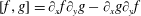 $[f,g]=\unicode[STIX]{x2202}_{x}f\unicode[STIX]{x2202}_{y}g-\unicode[STIX]{x2202}_{x}g\unicode[STIX]{x2202}_{y}f$
includes all of the nonlinearities and represents
$[f,g]=\unicode[STIX]{x2202}_{x}f\unicode[STIX]{x2202}_{y}g-\unicode[STIX]{x2202}_{x}g\unicode[STIX]{x2202}_{y}f$
includes all of the nonlinearities and represents
 $\boldsymbol{E}\times \boldsymbol{B}$
advection of
$\boldsymbol{E}\times \boldsymbol{B}$
advection of
 $g$
when
$g$
when
 $f=\unicode[STIX]{x1D711}$
and parallel derivation of
$f=\unicode[STIX]{x1D711}$
and parallel derivation of
 $g$
when
$g$
when
 $f=-\unicode[STIX]{x1D713}$
. The dimensionless parameters
$f=-\unicode[STIX]{x1D713}$
. The dimensionless parameters
 $\unicode[STIX]{x1D702}$
and
$\unicode[STIX]{x1D702}$
and
 $\unicode[STIX]{x1D707}$
are the plasma resistivity, corresponding to the inverse of the Lundquist number, and the kinematic viscosity, respectively. They are linked together through the magnetic Prandtl number
$\unicode[STIX]{x1D707}$
are the plasma resistivity, corresponding to the inverse of the Lundquist number, and the kinematic viscosity, respectively. They are linked together through the magnetic Prandtl number
 $P=\unicode[STIX]{x1D707}/\unicode[STIX]{x1D702}$
. We recall that in the adopted (standard) normalization, lengths are scaled to the macroscopic equilibrium magnetic field scale length
$P=\unicode[STIX]{x1D707}/\unicode[STIX]{x1D702}$
. We recall that in the adopted (standard) normalization, lengths are scaled to the macroscopic equilibrium magnetic field scale length
 $L$
, while the time is normalized on the Alfvèn time
$L$
, while the time is normalized on the Alfvèn time
 $\unicode[STIX]{x1D70F}_{A}$
, defined by the equilibrium poloidal magnetic field.
$\unicode[STIX]{x1D70F}_{A}$
, defined by the equilibrium poloidal magnetic field.
3 Theoretical analysis
As shown in Lazzaro & Comisso (Reference Lazzaro and Comisso2011), the problem of the response of a magnetic island to a localized current injection can be analytically treated as a converse of the classical Taylor problem. This problem addresses the response of a tearing stable state to a magnetic perturbation at the boundary of a plasma slab. The solution of this problem, obtained for the first time by Hahm & Kulsrud (Reference Hahm and Kulsrud1985), shows that two states could formally exist, one with a current sheet at a singular surface (state I) and one with a magnetic island (state II). Lazzaro & Comisso (Reference Lazzaro and Comisso2011) adopted the magnetic configuration associated with the state II of the Hahm and Kulsrud solution for analytically investigating the dynamics of a magnetic island in the presence of an external current source. Their results, valid for a resistive plasma, show that a suitable value of controlling current can lead to a new equilibrium state with no magnetic island. More recently, assuming a visco-resistive MHD plasma, it has been shown that the reconnection process in the Taylor problem depends on the external source perturbation (Comisso et al. Reference Comisso, Grasso and Waelbroeck2015). In particular a new scenario has been identified for sufficiently large boundary perturbations, characterized by the onset of a plasmoid-like instability (Comisso et al. Reference Comisso, Lingam, Huang and Bhattacharjee2016). In this section we exploit the results reported in Comisso et al. (Reference Comisso, Grasso and Waelbroeck2015) to extend the previous analysis reported in Lazzaro & Comisso (Reference Lazzaro and Comisso2011) and to investigate the small scale effects possibly triggered by an external current injection during the magnetic island control.
The solution of the linearized version of (2.3) and (2.4), in the absence of external current sources and assuming a stable equilibrium
 $\unicode[STIX]{x1D713}_{\text{eq}}\propto x^{2}$
in the external layer, is given in Hahm & Kulsrud (Reference Hahm and Kulsrud1985) as:
$\unicode[STIX]{x1D713}_{\text{eq}}\propto x^{2}$
in the external layer, is given in Hahm & Kulsrud (Reference Hahm and Kulsrud1985) as:
 $$\begin{eqnarray}\unicode[STIX]{x1D713}_{\text{out}}(x,y,t)=\left[\unicode[STIX]{x1D713}_{\text{out}}(0,t)\left(\cosh (kx)-\frac{\sinh (kx)}{\tanh (k)}\right)+\unicode[STIX]{x1D6F9}_{\unicode[STIX]{x1D6F4}}(t)\frac{\sinh (kx)}{\sinh (k)}\right]\cos (ky),\end{eqnarray}$$
where
 $\unicode[STIX]{x1D6F9}_{\unicode[STIX]{x1D6F4}}(t)$
is the amplitude of the time varying magnetic flux externally imposed at the boundary,
$\unicode[STIX]{x1D6F9}_{\unicode[STIX]{x1D6F4}}(t)$
is the amplitude of the time varying magnetic flux externally imposed at the boundary,
 $k=2\unicode[STIX]{x03C0}/L_{y}$
and
$k=2\unicode[STIX]{x03C0}/L_{y}$
and
 $L_{y}$
the slab extension in the
$L_{y}$
the slab extension in the
 $y$
-direction.
$y$
-direction.
Around the rational surface, at
 $x=0$
, the previous expression can be Taylor expanded and, adopting the same notation of Comisso et al. (Reference Comisso, Grasso and Waelbroeck2015), we can write the outer flux as
$x=0$
, the previous expression can be Taylor expanded and, adopting the same notation of Comisso et al. (Reference Comisso, Grasso and Waelbroeck2015), we can write the outer flux as
 $$\begin{eqnarray}\unicode[STIX]{x1D713}_{\text{out}}(x,t)=\unicode[STIX]{x1D713}_{\text{out}}(0,t)+{\textstyle \frac{1}{2}}(\unicode[STIX]{x1D6E5}_{0}^{\prime }\unicode[STIX]{x1D713}_{\text{out}}(t)|x|+\unicode[STIX]{x1D6E5}_{s}^{\prime }\unicode[STIX]{x1D6F9}_{\unicode[STIX]{x1D6F4}}(t)),\end{eqnarray}$$
where
 $$\begin{eqnarray}\unicode[STIX]{x1D6E5}_{0}^{\prime }=-\frac{2k}{\tanh (k)}\end{eqnarray}$$
is the standard tearing stability parameter (Furth, Killeen & Rosenbluth Reference Furth, Killeen and Rosenbluth1963) and
 $$\begin{eqnarray}\unicode[STIX]{x1D6E5}_{s}^{\prime }=\frac{2k}{\sinh (k)}\end{eqnarray}$$
parametrizes the discontinuity gradient related to the boundary perturbation.
In the presence of the externally applied control current, the linearized system of equations (2.3) and (2.4) reads
 $$\begin{eqnarray}\displaystyle & \displaystyle \unicode[STIX]{x2202}_{t}\unicode[STIX]{x1D713}_{1}+kx\unicode[STIX]{x1D719}_{1}=\unicode[STIX]{x1D702}[\unicode[STIX]{x1D713}_{1}^{\prime \prime }-J_{0}D(\unicode[STIX]{x1D713})] & \displaystyle\end{eqnarray}$$
 $$\begin{eqnarray}\displaystyle & \displaystyle \unicode[STIX]{x2202}_{t}\unicode[STIX]{x1D719}_{1}^{\prime \prime }=kx\unicode[STIX]{x1D713}_{1}^{\prime \prime }+\unicode[STIX]{x1D707}\unicode[STIX]{x1D719}_{1}^{IV}, & \displaystyle\end{eqnarray}$$
where we recall that
 $D(\unicode[STIX]{x1D713})$
models the spatial distribution of the control current. Following the calculations carried out in Comisso et al. (Reference Comisso, Grasso and Waelbroeck2015), we consider the change of variable
$D(\unicode[STIX]{x1D713})$
models the spatial distribution of the control current. Following the calculations carried out in Comisso et al. (Reference Comisso, Grasso and Waelbroeck2015), we consider the change of variable
 $\hat{x}=kx$
. Then, dropping the hats for the sake of clearness, Laplace and Fourier transforming as:
$\hat{x}=kx$
. Then, dropping the hats for the sake of clearness, Laplace and Fourier transforming as:
 $$\begin{eqnarray}\displaystyle & \displaystyle f_{L}(x,g)=\int _{0}^{\infty }f_{1}(x,t)\text{e}^{-gt}\,\text{d}t & \displaystyle\end{eqnarray}$$
 $$\begin{eqnarray}\displaystyle & \displaystyle f_{F}(\unicode[STIX]{x1D703},g)=\int _{-\infty }^{\infty }f_{L}(x,g)\text{e}^{-\text{i}\unicode[STIX]{x1D703}x}\,\text{d}x, & \displaystyle\end{eqnarray}$$
the set of equations (3.5) and (3.6) become:
 $$\begin{eqnarray}\displaystyle & \displaystyle g\unicode[STIX]{x1D713}_{F}+\text{i}\unicode[STIX]{x2202}_{\unicode[STIX]{x1D703}}\unicode[STIX]{x1D719}_{F}=-\unicode[STIX]{x1D702}(k^{2}\unicode[STIX]{x1D703}^{2}\unicode[STIX]{x1D713}_{F}-J_{0}D_{F}), & \displaystyle\end{eqnarray}$$
 $$\begin{eqnarray}\displaystyle & \displaystyle gk^{2}\unicode[STIX]{x1D703}^{2}\unicode[STIX]{x1D719}_{F}=\text{i}k^{2}\unicode[STIX]{x2202}_{\unicode[STIX]{x1D703}}(\unicode[STIX]{x1D703}^{2}\unicode[STIX]{x1D713}_{F})-\unicode[STIX]{x1D707}k^{4}\unicode[STIX]{x1D703}^{4}\unicode[STIX]{x1D719}_{F}. & \displaystyle\end{eqnarray}$$
Then, eliminating
 $\unicode[STIX]{x1D713}_{F}$
from (3.10) by means of (3.9), we obtain the layer equation
$\unicode[STIX]{x1D713}_{F}$
from (3.10) by means of (3.9), we obtain the layer equation
 $$\begin{eqnarray}\unicode[STIX]{x2202}_{\unicode[STIX]{x1D703}}\left(\frac{\unicode[STIX]{x1D703}^{2}}{g+\unicode[STIX]{x1D702}k^{2}\unicode[STIX]{x1D703}^{2}}\unicode[STIX]{x2202}_{\unicode[STIX]{x1D703}}\unicode[STIX]{x1D719}_{F}\right)-\unicode[STIX]{x1D703}^{2}(g+\unicode[STIX]{x1D707}k^{2}\unicode[STIX]{x1D703}^{2})\unicode[STIX]{x1D719}_{F}=\text{i}\unicode[STIX]{x1D702}J_{0}\unicode[STIX]{x2202}_{\unicode[STIX]{x1D703}}\frac{\unicode[STIX]{x1D703}^{2}D_{F}}{g+\unicode[STIX]{x1D702}k^{2}\unicode[STIX]{x1D703}^{2}}.\end{eqnarray}$$
This equation must be solved subject to the condition
 $$\begin{eqnarray}\lim _{\unicode[STIX]{x1D703}\rightarrow \infty }\unicode[STIX]{x1D719}_{F}\left(g,\unicode[STIX]{x1D703}\right)=0.\end{eqnarray}$$
In addition, the inner solution has to match the outer solution at (relatively) large
 $x$
, i.e. small
$x$
, i.e. small
 $\unicode[STIX]{x1D703}$
. This boundary condition can be obtained by neglecting resistivity in the linearized form of (2.3), and substituting
$\unicode[STIX]{x1D703}$
. This boundary condition can be obtained by neglecting resistivity in the linearized form of (2.3), and substituting
 $\unicode[STIX]{x1D713}_{\text{out}}(x,t)$
with its Taylor expansion around
$\unicode[STIX]{x1D713}_{\text{out}}(x,t)$
with its Taylor expansion around
 $x=0$
. Then, after using the Fourier–Laplace transform, the boundary condition for the inner solution reads:
$x=0$
. Then, after using the Fourier–Laplace transform, the boundary condition for the inner solution reads:
 $$\begin{eqnarray}\lim _{\unicode[STIX]{x1D703}\rightarrow 0}\unicode[STIX]{x1D719}_{F}(g,\unicode[STIX]{x1D703})=\frac{\text{i}g\unicode[STIX]{x1D713}_{\text{Lout}}(0,g)}{2}\left(\frac{\unicode[STIX]{x0394}(g)}{\unicode[STIX]{x03C0}k\unicode[STIX]{x1D703}}+1\right),\end{eqnarray}$$
where
 $$\begin{eqnarray}\unicode[STIX]{x0394}(g)\equiv \frac{\unicode[STIX]{x1D6E5}_{L}\unicode[STIX]{x1D713}_{\text{out}}(g)}{\unicode[STIX]{x1D713}_{\text{Lout}}(0,g)}.\end{eqnarray}$$
Applying the Laplace transform to (3.5) and substituting
 $\unicode[STIX]{x1D713}_{L}^{\prime \prime }=-\int _{-\infty }^{\infty }\unicode[STIX]{x1D703}^{2}\unicode[STIX]{x1D713}_{F}\text{e}^{\text{i}\unicode[STIX]{x1D703}x}\,\text{d}\unicode[STIX]{x1D703}$
we get the expression of the Laplace transformed flux evaluated at
$\unicode[STIX]{x1D713}_{L}^{\prime \prime }=-\int _{-\infty }^{\infty }\unicode[STIX]{x1D703}^{2}\unicode[STIX]{x1D713}_{F}\text{e}^{\text{i}\unicode[STIX]{x1D703}x}\,\text{d}\unicode[STIX]{x1D703}$
we get the expression of the Laplace transformed flux evaluated at
 $x=0$
as:
$x=0$
as:
 $$\begin{eqnarray}\unicode[STIX]{x1D713}_{L}(0,g)=-\frac{\unicode[STIX]{x1D702}k^{2}}{g}\lim _{x\rightarrow 0}\int _{-\infty }^{\infty }\unicode[STIX]{x1D703}^{2}\unicode[STIX]{x1D713}_{F}\text{e}^{\text{i}\unicode[STIX]{x1D703}x}\,\text{d}\unicode[STIX]{x1D703}-\frac{\unicode[STIX]{x1D702}}{g}J_{0}D_{L}(0,g).\end{eqnarray}$$
Then
 $\unicode[STIX]{x1D713}_{F}$
can be expressed in terms of
$\unicode[STIX]{x1D713}_{F}$
can be expressed in terms of
 $\unicode[STIX]{x1D719}_{F}$
from (3.10) as
$\unicode[STIX]{x1D719}_{F}$
from (3.10) as
 $$\begin{eqnarray}\unicode[STIX]{x1D713}_{F}=\frac{-\text{i}\unicode[STIX]{x2202}_{\unicode[STIX]{x1D703}}\unicode[STIX]{x1D719}_{F}-\unicode[STIX]{x1D702}J_{0}D_{F}}{g+\unicode[STIX]{x1D702}k^{2}\unicode[STIX]{x1D703}^{2}},\end{eqnarray}$$
to finally obtain
 $$\begin{eqnarray}\displaystyle \unicode[STIX]{x1D713}_{L}(0,g) & = & \displaystyle \lim _{x\rightarrow 0}\frac{2\unicode[STIX]{x1D702}k^{2}}{g}\int _{0}^{\infty }\frac{\text{i}\unicode[STIX]{x1D703}^{2}\unicode[STIX]{x2202}_{\unicode[STIX]{x1D703}}\unicode[STIX]{x1D719}_{F}}{g+\unicode[STIX]{x1D702}k^{2}\unicode[STIX]{x1D703}^{2}}\text{e}^{\text{i}\unicode[STIX]{x1D703}x}\,\text{d}\unicode[STIX]{x1D703}\nonumber\\ \displaystyle & & \displaystyle +\,\lim _{x\rightarrow 0}\frac{2\unicode[STIX]{x1D702}^{2}k^{2}J_{0}}{g}\int _{-\infty }^{\infty }\frac{\unicode[STIX]{x1D703}^{2}D_{F}}{g+\unicode[STIX]{x1D702}k^{2}\unicode[STIX]{x1D703}^{2}}\text{e}^{\text{i}\unicode[STIX]{x1D703}x}\,\text{d}\unicode[STIX]{x1D703}-\frac{\unicode[STIX]{x1D702}J_{0}D_{L}(0,g)}{g}.\end{eqnarray}$$
Now assuming the control current as a compact distribution, or in the limit case of Dirac’s delta, equations (3.17) and (3.11) reduce respectively to
 $$\begin{eqnarray}\unicode[STIX]{x1D713}_{L}(0,g)=\frac{2\unicode[STIX]{x1D702}k^{2}}{g}\int _{0}^{\infty }\frac{\text{i}\unicode[STIX]{x1D703}^{2}\unicode[STIX]{x2202}_{\unicode[STIX]{x1D703}}\unicode[STIX]{x1D719}_{F}}{g+\unicode[STIX]{x1D702}k^{2}\unicode[STIX]{x1D703}^{2}}\,\text{d}\unicode[STIX]{x1D703}-\frac{\unicode[STIX]{x1D702}J_{0}D_{L}(0,g)}{g}\end{eqnarray}$$
and
 $$\begin{eqnarray}\unicode[STIX]{x2202}_{\unicode[STIX]{x1D703}}\left(\frac{\unicode[STIX]{x1D703}^{2}}{g+\unicode[STIX]{x1D702}k^{2}\unicode[STIX]{x1D703}^{2}}\unicode[STIX]{x2202}_{\unicode[STIX]{x1D703}}\unicode[STIX]{x1D719}_{F}\right)-\unicode[STIX]{x1D703}^{2}(g+\unicode[STIX]{x1D707}k^{2}\unicode[STIX]{x1D703}^{2})\unicode[STIX]{x1D719}_{F}=\text{i}\unicode[STIX]{x1D702}J_{0}\unicode[STIX]{x2202}_{\unicode[STIX]{x1D703}}\frac{\unicode[STIX]{x1D703}^{2}}{g+\unicode[STIX]{x1D702}k^{2}\unicode[STIX]{x1D703}^{2}}.\end{eqnarray}$$
We use the standard asymptotic matching technique to solve (3.19). First, we look for the solution at large values of
 $\unicode[STIX]{x1D703}$
, defined by
$\unicode[STIX]{x1D703}$
, defined by
 $g\ll \unicode[STIX]{x1D702}k^{2}\unicode[STIX]{x1D703}^{2}$
. In this limit (3.19) reduces to
$g\ll \unicode[STIX]{x1D702}k^{2}\unicode[STIX]{x1D703}^{2}$
. In this limit (3.19) reduces to
 $$\begin{eqnarray}\unicode[STIX]{x2202}_{\unicode[STIX]{x1D703}}\frac{\unicode[STIX]{x1D703}^{2}}{g+\unicode[STIX]{x1D702}k^{2}\unicode[STIX]{x1D703}^{2}}=\frac{2\unicode[STIX]{x1D703}(g+\unicode[STIX]{x1D702}k^{2}\unicode[STIX]{x1D703}^{2})-2\unicode[STIX]{x1D702}k^{2}\unicode[STIX]{x1D703}^{3}}{(g+\unicode[STIX]{x1D702}k^{2}\unicode[STIX]{x1D703}^{2})^{2}}=\frac{2\unicode[STIX]{x1D703}g}{(g+\unicode[STIX]{x1D702}k^{2}\unicode[STIX]{x1D703}^{2})^{2}}.\end{eqnarray}$$
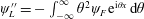
This equation can be solved following Comisso et al. (Reference Comisso, Grasso and Waelbroeck2015). The final solution that vanishes correctly as
 $\unicode[STIX]{x1D703}\rightarrow \infty$
is
$\unicode[STIX]{x1D703}\rightarrow \infty$
is
 $$\begin{eqnarray}\unicode[STIX]{x1D719}_{F>}=c_{2}\unicode[STIX]{x1D703}^{1/2}K_{1/6}\left(\frac{\unicode[STIX]{x1D703}^{3}}{3\unicode[STIX]{x1D714}^{3}}\right),\end{eqnarray}$$
where
 $\unicode[STIX]{x1D714}\equiv (\unicode[STIX]{x1D702}\unicode[STIX]{x1D707}k^{4})^{-1/6}$
.
$\unicode[STIX]{x1D714}\equiv (\unicode[STIX]{x1D702}\unicode[STIX]{x1D707}k^{4})^{-1/6}$
.
In the opposite limit of small
 $\unicode[STIX]{x1D703}$
(i.e. large
$\unicode[STIX]{x1D703}$
(i.e. large
 $x$
), defined by the inequality
$x$
), defined by the inequality
 $\unicode[STIX]{x1D703}<(\unicode[STIX]{x1D707}\unicode[STIX]{x1D702}k^{4})^{-1/6}$
, the right-hand side of (3.19) reduces to
$\unicode[STIX]{x1D703}<(\unicode[STIX]{x1D707}\unicode[STIX]{x1D702}k^{4})^{-1/6}$
, the right-hand side of (3.19) reduces to
 $2\unicode[STIX]{x1D703}g/(g+\unicode[STIX]{x1D702}k^{2}\unicode[STIX]{x1D703}^{2})^{2}\approx 2\unicode[STIX]{x1D703}\rightarrow 0$
and thus
$2\unicode[STIX]{x1D703}g/(g+\unicode[STIX]{x1D702}k^{2}\unicode[STIX]{x1D703}^{2})^{2}\approx 2\unicode[STIX]{x1D703}\rightarrow 0$
and thus
 $$\begin{eqnarray}\unicode[STIX]{x2202}_{\unicode[STIX]{x1D703}}\left(\frac{\unicode[STIX]{x1D703}^{2}}{g+\unicode[STIX]{x1D702}k^{2}\unicode[STIX]{x1D703}^{2}}\unicode[STIX]{x2202}_{\unicode[STIX]{x1D703}}\unicode[STIX]{x1D719}_{F<}\right)=0.\end{eqnarray}$$
Again we follow exactly Comisso et al. (Reference Comisso, Grasso and Waelbroeck2015) and, applying the boundary conditions (3.13), write the final solution as:
 $$\begin{eqnarray}\unicode[STIX]{x1D719}_{F<}=\left(-\frac{g}{\unicode[STIX]{x1D703}}+\unicode[STIX]{x1D702}k^{2}\unicode[STIX]{x1D703}\right)\text{i}\frac{\unicode[STIX]{x0394}(g)}{2\unicode[STIX]{x03C0}k}\unicode[STIX]{x1D713}_{\text{Lout}}(0,g)-\text{i}\frac{g}{2}\unicode[STIX]{x1D713}_{\text{Lout}}(0,g).\end{eqnarray}$$
By matching the solutions
 $\unicode[STIX]{x1D719}_{F>}$
and
$\unicode[STIX]{x1D719}_{F>}$
and
 $\unicode[STIX]{x1D719}_{F<}$
in the overlapping interval we end up with
$\unicode[STIX]{x1D719}_{F<}$
in the overlapping interval we end up with
 $$\begin{eqnarray}\unicode[STIX]{x0394}(g)=g\unicode[STIX]{x1D70F}_{\ast },\end{eqnarray}$$
where
 $$\begin{eqnarray}\unicode[STIX]{x1D70F}_{\ast }=\unicode[STIX]{x03C0}6^{2/3}\frac{\unicode[STIX]{x1D6E4}({\textstyle \frac{5}{6}})}{\unicode[STIX]{x1D6E4}({\textstyle \frac{1}{6}})}\frac{\unicode[STIX]{x1D707}^{1/6}}{k^{1/3}\unicode[STIX]{x1D702}^{5/6}}.\end{eqnarray}$$
When
 $g\ll \unicode[STIX]{x1D702}k^{2}\unicode[STIX]{x1D703}^{2}$
from (3.18) we can evaluate the reconnected Laplace transformed flux as
$g\ll \unicode[STIX]{x1D702}k^{2}\unicode[STIX]{x1D703}^{2}$
from (3.18) we can evaluate the reconnected Laplace transformed flux as
 $$\begin{eqnarray}\unicode[STIX]{x1D713}_{L}(0,g)=\unicode[STIX]{x1D713}_{\text{Lout}}(0,g)-\frac{\unicode[STIX]{x1D702}J_{0}D_{L}(0,g)}{g}.\end{eqnarray}$$
 $\unicode[STIX]{x1D713}_{\text{Lout}}(0,g)$
can now be obtained by Laplace transforming the gradient discontinuity evaluated at the rational surface
$\unicode[STIX]{x1D713}_{\text{Lout}}(0,g)$
can now be obtained by Laplace transforming the gradient discontinuity evaluated at the rational surface
 $x=0$
to get
$x=0$
to get
 $$\begin{eqnarray}\unicode[STIX]{x1D713}_{\text{Lout}}(0,g)=\frac{\unicode[STIX]{x1D6E5}_{s}^{\prime }\unicode[STIX]{x1D6F9}_{\unicode[STIX]{x1D6F4}}(g)}{g(\unicode[STIX]{x0394}(g)-\unicode[STIX]{x1D6E5}_{0}^{\prime })}.\end{eqnarray}$$
Then inserting the expression (3.27) into (3.26) we obtain
 $$\begin{eqnarray}\unicode[STIX]{x1D713}_{L}(0,g)=\frac{\unicode[STIX]{x1D6E5}_{s}^{\prime }\unicode[STIX]{x1D6F9}_{\unicode[STIX]{x1D6F4}}(g)}{g(\unicode[STIX]{x0394}(g)-\unicode[STIX]{x1D6E5}_{0}^{\prime })}-\frac{\unicode[STIX]{x1D702}J_{0}D_{L}(0,g)}{g}.\end{eqnarray}$$
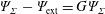
If we now define the total external contribution as
 $$\begin{eqnarray}\unicode[STIX]{x1D6F9}_{\text{ext}}(g)=\unicode[STIX]{x1D6F9}_{\unicode[STIX]{x1D6F4}}-\unicode[STIX]{x1D702}J_{0}D_{L}(0,g)\frac{\unicode[STIX]{x0394}(g)-\unicode[STIX]{x1D6E5}_{0}^{\prime }}{\unicode[STIX]{x1D6E5}_{s}^{\prime }},\end{eqnarray}$$
it is clear from (3.29) that a good choice of
 $J_{0}(t)$
can control the reconnected flux amplitude, i.e. the island width. This condition can be expressed in terms of a partial suppression parameter
$J_{0}(t)$
can control the reconnected flux amplitude, i.e. the island width. This condition can be expressed in terms of a partial suppression parameter
 $G$
,
$G$
,
 $(0<G<1)$
, writing
$(0<G<1)$
, writing
 $\unicode[STIX]{x1D6F9}_{\unicode[STIX]{x1D6F4}}-\unicode[STIX]{x1D6F9}_{\text{ext}}=G\unicode[STIX]{x1D6F9}_{\unicode[STIX]{x1D6F4}}$
. Combining then (3.28) and (3.29) and introducing the Lundquist number
$\unicode[STIX]{x1D6F9}_{\unicode[STIX]{x1D6F4}}-\unicode[STIX]{x1D6F9}_{\text{ext}}=G\unicode[STIX]{x1D6F9}_{\unicode[STIX]{x1D6F4}}$
. Combining then (3.28) and (3.29) and introducing the Lundquist number
 $S=1/\unicode[STIX]{x1D702}$
, we obtain the control condition
$S=1/\unicode[STIX]{x1D702}$
, we obtain the control condition
 $$\begin{eqnarray}\frac{\unicode[STIX]{x0394}(g)-\unicode[STIX]{x1D6E5}_{0}^{\prime }}{S\unicode[STIX]{x1D6E5}_{s}^{\prime }}J_{0}D_{L}(0,g)=G\unicode[STIX]{x1D6F9}_{\unicode[STIX]{x1D6F4}},\end{eqnarray}$$
and, after using (3.24), we find
 $$\begin{eqnarray}g\unicode[STIX]{x1D713}_{L}(0,g)=\frac{\unicode[STIX]{x1D6E5}_{s}^{\prime }\unicode[STIX]{x1D6F9}_{\text{ext}}}{\displaystyle \unicode[STIX]{x1D70F}_{\ast }\left(S-\frac{\unicode[STIX]{x1D6E5}_{0}^{\prime }}{\unicode[STIX]{x1D70F}_{\ast }}\right)}.\end{eqnarray}$$
Inverse transforming the previous equation and then integrating we get the final solution for the reconnected flux at the rational surface:
 $$\begin{eqnarray}\unicode[STIX]{x1D713}(0,t)=\frac{\unicode[STIX]{x1D6E5}_{s}^{\prime }\unicode[STIX]{x1D6F9}_{\text{ext}}}{\unicode[STIX]{x1D6E5}_{0}^{\prime }}\text{e}^{\frac{\unicode[STIX]{x1D6E5}_{0}^{\prime }t}{\unicode[STIX]{x1D70F}_{\ast }}}-\frac{\unicode[STIX]{x1D6E5}_{s}^{\prime }\unicode[STIX]{x1D6F9}_{\text{ext}}}{\unicode[STIX]{x1D6E5}_{0}^{\prime }}.\end{eqnarray}$$
From the previous equation it is clear that with
 $\unicode[STIX]{x1D713}(0,t)$
proportional to
$\unicode[STIX]{x1D713}(0,t)$
proportional to
 $\unicode[STIX]{x1D6F9}_{\text{ext}}$
the magnetic island can be suppressed or controlled by a suitable choice of
$\unicode[STIX]{x1D6F9}_{\text{ext}}$
the magnetic island can be suppressed or controlled by a suitable choice of
 $J_{0}$
.
$J_{0}$
.
It is important to observe that when a constant
 $\unicode[STIX]{x1D713}$
island shrinks below a critical value, if the driven current has a scale length (absorption depth) comparable to this critical value, the perturbation can be driven into a non-constant
$\unicode[STIX]{x1D713}$
island shrinks below a critical value, if the driven current has a scale length (absorption depth) comparable to this critical value, the perturbation can be driven into a non-constant
 $\unicode[STIX]{x1D713}$
regime, where instability conditions can be reached for tearing unstable current sheets and secondary island structures. Indeed, in the visco-resistive regime, according to Comisso et al. (Reference Comisso, Grasso and Waelbroeck2015, Reference Comisso, Lingam, Huang and Bhattacharjee2016), a nonlinear instability condition should be reached when, under the ECCD effect, the island approaches from above (in a controlled fashion) the dimensionless critical width
$\unicode[STIX]{x1D713}$
regime, where instability conditions can be reached for tearing unstable current sheets and secondary island structures. Indeed, in the visco-resistive regime, according to Comisso et al. (Reference Comisso, Grasso and Waelbroeck2015, Reference Comisso, Lingam, Huang and Bhattacharjee2016), a nonlinear instability condition should be reached when, under the ECCD effect, the island approaches from above (in a controlled fashion) the dimensionless critical width
 $w_{\text{crit}}=4\sqrt{\unicode[STIX]{x1D6F9}_{\text{crit}}}$
, where
$w_{\text{crit}}=4\sqrt{\unicode[STIX]{x1D6F9}_{\text{crit}}}$
, where
 $$\begin{eqnarray}\unicode[STIX]{x1D6F9}_{\text{crit}}=C\frac{k}{S\unicode[STIX]{x1D6E5}_{s}^{\prime }}\sqrt{1+P}.\end{eqnarray}$$
Here,
 $C$
is a parameter related to the marginally stable current sheets aspect ratio. This critical condition for the development of the plasmoid instability can be transferred into a condition on the EC current beam size compared to the island width:
$C$
is a parameter related to the marginally stable current sheets aspect ratio. This critical condition for the development of the plasmoid instability can be transferred into a condition on the EC current beam size compared to the island width:
 $$\begin{eqnarray}\unicode[STIX]{x1D6F9}_{\text{ext}}=\unicode[STIX]{x1D6F9}_{\unicode[STIX]{x1D6F4}}(1-G)\geqslant \frac{\unicode[STIX]{x1D702}Ck\sqrt{1+P}}{\unicode[STIX]{x1D6E5}_{s}^{\prime }}.\end{eqnarray}$$
Exploiting (3.30) this condition can be rewritten as:
 $$\begin{eqnarray}J_{0}D_{L}(0,g)\frac{\unicode[STIX]{x0394}(g)-\unicode[STIX]{x1D6E5}_{0}^{\prime }}{SG\unicode[STIX]{x1D6E5}_{s}^{\prime }}\geqslant \frac{\unicode[STIX]{x1D702}Ck\sqrt{1+P}}{\unicode[STIX]{x1D6E5}_{s}^{\prime }}.\end{eqnarray}$$
If we assume a Gaussian behaviour of width
 $\unicode[STIX]{x1D6FF}_{\text{CD}}$
for the spatial distribution
$\unicode[STIX]{x1D6FF}_{\text{CD}}$
for the spatial distribution
 $D(\unicode[STIX]{x1D713})$
, we can rewrite the previous equation as
$D(\unicode[STIX]{x1D713})$
, we can rewrite the previous equation as
 $$\begin{eqnarray}\frac{2J_{0}}{\unicode[STIX]{x1D6FF}_{\text{CD}}\sqrt{\unicode[STIX]{x03C0}}}\frac{\unicode[STIX]{x0394}(g)-\unicode[STIX]{x1D6E5}_{0}^{\prime }}{SG\unicode[STIX]{x1D6E5}_{s}^{\prime }}\geqslant \frac{\unicode[STIX]{x1D702}Ck\sqrt{1+P}}{\unicode[STIX]{x1D6E5}_{s}^{\prime }},\end{eqnarray}$$
where
 $J_{0}$
is the total injected current at the beginning of the control. This expression can be read as a condition for the deposition length of the control current respect of the peaking value as:
$J_{0}$
is the total injected current at the beginning of the control. This expression can be read as a condition for the deposition length of the control current respect of the peaking value as:
 $$\begin{eqnarray}\frac{\unicode[STIX]{x1D6FF}_{\text{CD}}}{J_{0}}\leqslant \frac{\sqrt{\unicode[STIX]{x03C0}}(1-G)(\unicode[STIX]{x0394}(g)-\unicode[STIX]{x1D6E5}_{0}^{\prime })}{2GCk\sqrt{1+P}}.\end{eqnarray}$$
We note that given a deposition depth and a current drive the presence of the viscosity makes it harder to reach the plasmoids-like regime.
4 Numerical results
The theoretical results reported in the previous section highlight the effects of the amplitude
 $J_{0}$
and the width
$J_{0}$
and the width
 $\unicode[STIX]{x1D6FF}_{\text{CD}}$
of the ECCD on the control of a magnetic island sustained by a boundary forcing contribution. However this analysis is quite general and remains valid, at least qualitatively, also for spontaneous reconnection events, typical of the tokamak scenarios (White Reference White1986). Recent numerical simulations (Lazzaro et al.
Reference Lazzaro, Borgogno, Brunetti and Comisso2018), in fact, pointed out the role of the ECCD beam width on the onset of plasmoid-like instabilities when the control is applied on a large, nonlinear magnetic island rising from a linearly unstable equilibrium configuration. In particular the simulations showed that the smaller the
$\unicode[STIX]{x1D6FF}_{\text{CD}}$
of the ECCD on the control of a magnetic island sustained by a boundary forcing contribution. However this analysis is quite general and remains valid, at least qualitatively, also for spontaneous reconnection events, typical of the tokamak scenarios (White Reference White1986). Recent numerical simulations (Lazzaro et al.
Reference Lazzaro, Borgogno, Brunetti and Comisso2018), in fact, pointed out the role of the ECCD beam width on the onset of plasmoid-like instabilities when the control is applied on a large, nonlinear magnetic island rising from a linearly unstable equilibrium configuration. In particular the simulations showed that the smaller the
 $\unicode[STIX]{x1D6FF}_{\text{CD}}$
, the more lively the dynamics of the plasmoids, according to the prediction of (3.37).
$\unicode[STIX]{x1D6FF}_{\text{CD}}$
, the more lively the dynamics of the plasmoids, according to the prediction of (3.37).
The results reported in Lazzaro et al. (Reference Lazzaro, Borgogno, Brunetti and Comisso2018) have been obtained in a rather unstable, large
 $\unicode[STIX]{x1D6E5}^{\prime }$
, configuration, assuming a purely resistive plasma. In this section we want to generalize these results, first by considering less unstable regimes, that are close to the operation condition in tokamaks, and then by investigating the effects of the kinematic viscosity on the efficacy of the island control.
$\unicode[STIX]{x1D6E5}^{\prime }$
, configuration, assuming a purely resistive plasma. In this section we want to generalize these results, first by considering less unstable regimes, that are close to the operation condition in tokamaks, and then by investigating the effects of the kinematic viscosity on the efficacy of the island control.
We adopt the same numerical approach described in Borgogno et al. (Reference Borgogno, Comisso, Grasso and Lazzaro2014). The equations (2.3)–(2.4) are numerically solved in the presence of a static ‘Harris pinch’ equilibrium configuration with
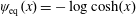 $\unicode[STIX]{x1D713}_{\text{eq}}(x)=-\log \cosh (x)$
. We recall that this equilibrium is tearing mode unstable if the instability parameter
$\unicode[STIX]{x1D713}_{\text{eq}}(x)=-\log \cosh (x)$
. We recall that this equilibrium is tearing mode unstable if the instability parameter
 $\unicode[STIX]{x1D6E5}^{\prime }=2\cdot (1/k_{y}-k_{y})>0$
, where
$\unicode[STIX]{x1D6E5}^{\prime }=2\cdot (1/k_{y}-k_{y})>0$
, where
 $k_{y}=2\unicode[STIX]{x03C0}m/L_{y}$
, with
$k_{y}=2\unicode[STIX]{x03C0}m/L_{y}$
, with
 $m$
the corresponding mode number and
$m$
the corresponding mode number and
 $L_{y}$
the length of the domain along the
$L_{y}$
the length of the domain along the
 $y$
-direction. The profile of the control current density is assumed to be Gaussian
$y$
-direction. The profile of the control current density is assumed to be Gaussian
 $$\begin{eqnarray}J_{\text{CD}}(x,y,t)=J_{m}(t)\exp \left(-\frac{(\unicode[STIX]{x1D713}(x,y,t)-\unicode[STIX]{x1D713}_{O}(t))^{2}}{\unicode[STIX]{x1D6FF}_{\text{CD}}^{2}}\right),\end{eqnarray}$$
where
 $\unicode[STIX]{x1D713}_{O}$
is the magnetic flux evaluated at the position of the magnetic island
$\unicode[STIX]{x1D713}_{O}$
is the magnetic flux evaluated at the position of the magnetic island
 $O$
-point at the beginning of the control stage. The peak amplitude
$O$
-point at the beginning of the control stage. The peak amplitude
 $J_{0}$
has a step function time waveform
$J_{0}$
has a step function time waveform
 $$\begin{eqnarray}J_{m}(t)=\left\{\begin{array}{@{}ll@{}}0\quad & t<t_{1}\vee t>t_{2},\\ J_{0}\quad & t_{1}<t<t_{2},\end{array}\right.\end{eqnarray}$$
where
 $t_{1}$
and
$t_{1}$
and
 $t_{2}$
are the switching on and switching off time of the current control, respectively. The amplitude
$t_{2}$
are the switching on and switching off time of the current control, respectively. The amplitude
 $J_{0}$
is a constant proportional to the difference between the current density values at the
$J_{0}$
is a constant proportional to the difference between the current density values at the
 $X$
- and
$X$
- and
 $O$
-points of the magnetic island at
$O$
-points of the magnetic island at
 $t=t_{1}$
, i.e.
$t=t_{1}$
, i.e.
 $J_{0}=a\cdot (J_{X}(t_{1})-J_{O}(t_{1}))$
. Finally, the EC beam width in
$J_{0}=a\cdot (J_{X}(t_{1})-J_{O}(t_{1}))$
. Finally, the EC beam width in
 $\unicode[STIX]{x1D713}$
space,
$\unicode[STIX]{x1D713}$
space,
 $\unicode[STIX]{x1D6FF}_{\text{CD}}$
, is taken proportional to the difference between the magnetic flux at the
$\unicode[STIX]{x1D6FF}_{\text{CD}}$
, is taken proportional to the difference between the magnetic flux at the
 $X$
- and the
$X$
- and the
 $O$
-point of the magnetic island when
$O$
-point of the magnetic island when
 $t=t_{1}$
, i.e.
$t=t_{1}$
, i.e.
 $\unicode[STIX]{x1D6FF}_{\text{CD}}=b\cdot (\unicode[STIX]{x1D713}_{X}(t_{1})-\unicode[STIX]{x1D713}_{O}(t_{1}))$
.
$\unicode[STIX]{x1D6FF}_{\text{CD}}=b\cdot (\unicode[STIX]{x1D713}_{X}(t_{1})-\unicode[STIX]{x1D713}_{O}(t_{1}))$
.
Here we apply the ECCD to an
 $m=1$
island associated with a weakly unstable perturbation, with
$m=1$
island associated with a weakly unstable perturbation, with
 $\unicode[STIX]{x1D6E5}^{\prime }=3$
, while in Lazzaro et al. (Reference Lazzaro, Borgogno, Brunetti and Comisso2018) the linear instability parameter was
$\unicode[STIX]{x1D6E5}^{\prime }=3$
, while in Lazzaro et al. (Reference Lazzaro, Borgogno, Brunetti and Comisso2018) the linear instability parameter was
 $\unicode[STIX]{x1D6E5}^{\prime }=7.5$
. The plasma resistivity is the same in both cases,
$\unicode[STIX]{x1D6E5}^{\prime }=7.5$
. The plasma resistivity is the same in both cases,
 $\unicode[STIX]{x1D702}=5\times 10^{-4}$
.
$\unicode[STIX]{x1D702}=5\times 10^{-4}$
.
Figure 1(a) shows the current density distribution and the corresponding magnetic island at the beginning of the ECCD injection. The time
 $t_{1}$
corresponds to a nonlinear stage of the magnetic island evolution (figure 1
b), in the so-called Rutherford phase (Rutherford Reference Rutherford1973), where the magnetic island width is of the order of the equilibrium shear length. The choice of this time is consistent with the request that the growth rates in the regimes
$t_{1}$
corresponds to a nonlinear stage of the magnetic island evolution (figure 1
b), in the so-called Rutherford phase (Rutherford Reference Rutherford1973), where the magnetic island width is of the order of the equilibrium shear length. The choice of this time is consistent with the request that the growth rates in the regimes
 $\unicode[STIX]{x1D6E5}^{\prime }=3$
and
$\unicode[STIX]{x1D6E5}^{\prime }=3$
and
 $\unicode[STIX]{x1D6E5}^{\prime }=7.5$
, normalized to the corresponding linear growth rates, are the same when the ECCD is turned on. As a consequence the magnetic island width in the most unstable regime is approximately twice the width in the less unstable case.
$\unicode[STIX]{x1D6E5}^{\prime }=7.5$
, normalized to the corresponding linear growth rates, are the same when the ECCD is turned on. As a consequence the magnetic island width in the most unstable regime is approximately twice the width in the less unstable case.

Figure 1. (a) Contour plot of the current density at the beginning of the ECCD injection in the regime
 $\unicode[STIX]{x1D6E5}^{\prime }=3$
. The superimposed white lines identify the borders of the corresponding reconnected region. (b) Time evolution of the area of the reconnected region in the absence of rf control. The dashed line identifies the starting injection time
$\unicode[STIX]{x1D6E5}^{\prime }=3$
. The superimposed white lines identify the borders of the corresponding reconnected region. (b) Time evolution of the area of the reconnected region in the absence of rf control. The dashed line identifies the starting injection time
 $t_{1}$
, and the blue dot shows the time when the current is plotted.
$t_{1}$
, and the blue dot shows the time when the current is plotted.
According to Lazzaro et al. (Reference Lazzaro, Borgogno, Brunetti and Comisso2018) we adopt different widths of the ECCD beam deposition, while the initially injected total ECCD current,
 $\int J_{\text{CD}}(x,y,t_{1})\,\text{d}x\,\text{d}y$
, is the same. As far as the parameter
$\int J_{\text{CD}}(x,y,t_{1})\,\text{d}x\,\text{d}y$
, is the same. As far as the parameter
 $b$
is relatively large the control current efficacy is low in both regimes. Figure 2 refers to the
$b$
is relatively large the control current efficacy is low in both regimes. Figure 2 refers to the
 $b=2$
case for
$b=2$
case for
 $\unicode[STIX]{x1D6E5}^{\prime }=3$
. The magnetic island shrinks monotonically until the system reaches a new equilibrium on a time scale
$\unicode[STIX]{x1D6E5}^{\prime }=3$
. The magnetic island shrinks monotonically until the system reaches a new equilibrium on a time scale
 $1/\unicode[STIX]{x1D6FE}_{\text{lin}}$
, where
$1/\unicode[STIX]{x1D6FE}_{\text{lin}}$
, where
 $\unicode[STIX]{x1D6FE}_{\text{lin}}\approx 0.01$
is the linear growth rate of the non-controlled reconnecting mode. We note that the saturated island area has the same order of magnitude of the area at
$\unicode[STIX]{x1D6FE}_{\text{lin}}\approx 0.01$
is the linear growth rate of the non-controlled reconnecting mode. We note that the saturated island area has the same order of magnitude of the area at
 $t=t_{1}$
, resulting in a completely ineffective control. The topology of the magnetic island remains the same during the control process, while in the more unstable regime the saturation phase is dominated by the mode
$t=t_{1}$
, resulting in a completely ineffective control. The topology of the magnetic island remains the same during the control process, while in the more unstable regime the saturation phase is dominated by the mode
 $m=2$
. This behaviour reflects the linear properties of the system in the two regimes (Militello, Grasso & Borgogno Reference Militello, Grasso and Borgogno2014). While in
$m=2$
. This behaviour reflects the linear properties of the system in the two regimes (Militello, Grasso & Borgogno Reference Militello, Grasso and Borgogno2014). While in
 $\unicode[STIX]{x1D6E5}^{\prime }=7.5$
the two unstable modes
$\unicode[STIX]{x1D6E5}^{\prime }=7.5$
the two unstable modes
 $m=1$
and
$m=1$
and
 $m=2$
grow with comparable rates, for
$m=2$
grow with comparable rates, for
 $\unicode[STIX]{x1D6E5}^{\prime }=3$
just the
$\unicode[STIX]{x1D6E5}^{\prime }=3$
just the
 $m=1$
perturbation is linearly unstable.
$m=1$
perturbation is linearly unstable.

Figure 2. (a) Contour plot of the current density in the presence of an ECCD beam of width
 $\unicode[STIX]{x1D6FF}_{\text{CD}}=b(\unicode[STIX]{x1D713}_{X}-\unicode[STIX]{x1D713}_{O})$
with
$\unicode[STIX]{x1D6FF}_{\text{CD}}=b(\unicode[STIX]{x1D713}_{X}-\unicode[STIX]{x1D713}_{O})$
with
 $b=2$
in the regime
$b=2$
in the regime
 $\unicode[STIX]{x1D6E5}^{\prime }=3$
. The superimposed white lines identify the borders of the corresponding reconnected region. (b) Time evolution of the area of the reconnected region. The dashed line identifies the starting injection time
$\unicode[STIX]{x1D6E5}^{\prime }=3$
. The superimposed white lines identify the borders of the corresponding reconnected region. (b) Time evolution of the area of the reconnected region. The dashed line identifies the starting injection time
 $t_{1}$
, while the blue dot shows the time when the current is plotted.
$t_{1}$
, while the blue dot shows the time when the current is plotted.

Figure 3. (a) Contour plot of the current density in the presence of an ECCD beam of width
 $\unicode[STIX]{x1D6FF}_{\text{CD}}=b(\unicode[STIX]{x1D713}_{X}-\unicode[STIX]{x1D713}_{O})$
with
$\unicode[STIX]{x1D6FF}_{\text{CD}}=b(\unicode[STIX]{x1D713}_{X}-\unicode[STIX]{x1D713}_{O})$
with
 $b=1$
in the regime
$b=1$
in the regime
 $\unicode[STIX]{x1D6E5}^{\prime }=7.5$
. The superimposed white lines identify the borders of the corresponding reconnected region. (b) Time evolution of the area of the reconnected region. The dashed line identifies the starting injection time
$\unicode[STIX]{x1D6E5}^{\prime }=7.5$
. The superimposed white lines identify the borders of the corresponding reconnected region. (b) Time evolution of the area of the reconnected region. The dashed line identifies the starting injection time
 $t_{1}$
, while the blue dot shows the time when the current is plotted.
$t_{1}$
, while the blue dot shows the time when the current is plotted.
Major differences appear when the ECCD beam is smaller than the magnetic island width at
 $t=t_{1}$
. We consider first the case
$t=t_{1}$
. We consider first the case
 $b=1$
, shown in figure 3. After an initial decreasing phase, the higher
$b=1$
, shown in figure 3. After an initial decreasing phase, the higher
 $\unicode[STIX]{x1D6E5}^{\prime }$
regime is characterized by the onset of a plasmoid-like instability. As shown in figure 4, by the contour plot and the profile at
$\unicode[STIX]{x1D6E5}^{\prime }$
regime is characterized by the onset of a plasmoid-like instability. As shown in figure 4, by the contour plot and the profile at
 $x=0$
of the rf current density at the same time as figure 3, in this phase, the magnetic flux function exhibits a uniform distribution around the reconnection region and, according to (4.1), the same is true for the control current. This condition makes almost negligible the ECCD contribution in reducing the island area. In fact it strongly differs from the ideal control configuration, represented at the injection initial time
$x=0$
of the rf current density at the same time as figure 3, in this phase, the magnetic flux function exhibits a uniform distribution around the reconnection region and, according to (4.1), the same is true for the control current. This condition makes almost negligible the ECCD contribution in reducing the island area. In fact it strongly differs from the ideal control configuration, represented at the injection initial time
 $t_{1}$
in figure 5, where it is clear that
$t_{1}$
in figure 5, where it is clear that
 $J_{\text{CD}}$
is peaked at the
$J_{\text{CD}}$
is peaked at the
 $O$
-point of the magnetic island. On the other hand, we have verified that, when
$O$
-point of the magnetic island. On the other hand, we have verified that, when
 $\unicode[STIX]{x1D6E5}^{\prime }=3$
, plasmoids are completely absent and the ECCD control is optimal, leading to the rapid annihilation of the magnetic island (see figure 6). Note that the island suppression does not proceed monotonically in time, but it exhibits a strong discontinuity at
$\unicode[STIX]{x1D6E5}^{\prime }=3$
, plasmoids are completely absent and the ECCD control is optimal, leading to the rapid annihilation of the magnetic island (see figure 6). Note that the island suppression does not proceed monotonically in time, but it exhibits a strong discontinuity at
 $t\approx 2250$
. At this time the area of the island bounces back with a growth rate equal to the previous rate of quench. This is the consequence of the so called flip instability (Monticello et al.
Reference Monticello, White and Rosenbluth1978; Lazzaro & Coelho Reference Lazzaro and Coelho2002), that has already been observed in numerical experiments of early control activity (Borgogno et al.
Reference Borgogno, Comisso, Grasso and Lazzaro2014; Fevrier et al.
Reference Fevrier, Maget and Lutjens2016). At the onset of the instability the value of the reconnected flux
$t\approx 2250$
. At this time the area of the island bounces back with a growth rate equal to the previous rate of quench. This is the consequence of the so called flip instability (Monticello et al.
Reference Monticello, White and Rosenbluth1978; Lazzaro & Coelho Reference Lazzaro and Coelho2002), that has already been observed in numerical experiments of early control activity (Borgogno et al.
Reference Borgogno, Comisso, Grasso and Lazzaro2014; Fevrier et al.
Reference Fevrier, Maget and Lutjens2016). At the onset of the instability the value of the reconnected flux
 $\unicode[STIX]{x1D713}_{X}-\unicode[STIX]{x1D713}_{O}$
changes sign, which is equivalent to a shift of
$\unicode[STIX]{x1D713}_{X}-\unicode[STIX]{x1D713}_{O}$
changes sign, which is equivalent to a shift of
 $L_{y}/2$
of the equilibrium position of the elliptic
$L_{y}/2$
of the equilibrium position of the elliptic
 $O$
-point of the tearing perturbation (figure 6
a,b). Due to this island shift the
$O$
-point of the tearing perturbation (figure 6
a,b). Due to this island shift the
 $X$
-point happens to be now under the influence of the rf driven current that drives the growth of the magnetic island. However, if the deposition of the rf driven current is broad enough the magnetic island may grow to intercept the stabilizing current at its
$X$
-point happens to be now under the influence of the rf driven current that drives the growth of the magnetic island. However, if the deposition of the rf driven current is broad enough the magnetic island may grow to intercept the stabilizing current at its
 $O$
-point and decreases again.
$O$
-point and decreases again.

Figure 4. (a) Contour plot of the rf current density at the same time as the contour plot shown in figure 3. The superimposed white lines identify the borders of the corresponding reconnected region. (b) Profile of the rf current density at
 $x=0$
for the same time. The dashed line corresponds to the
$x=0$
for the same time. The dashed line corresponds to the
 $\unicode[STIX]{x1D713}$
profile.
$\unicode[STIX]{x1D713}$
profile.

Figure 5. (a) Contour plot of the rf current density at
 $t=t_{1}$
corresponding to the case represented in figure 3. The superimposed white lines identify the borders of the corresponding reconnected region. (b) Profile of the rf current density at
$t=t_{1}$
corresponding to the case represented in figure 3. The superimposed white lines identify the borders of the corresponding reconnected region. (b) Profile of the rf current density at
 $x=0$
for the same time. The dashed line corresponds to the
$x=0$
for the same time. The dashed line corresponds to the
 $\unicode[STIX]{x1D713}$
profile.
$\unicode[STIX]{x1D713}$
profile.

Figure 6. (a,b) Contour plots of the current density in the presence of an ECCD beam of width
 $\unicode[STIX]{x1D6FF}_{\text{CD}}=b(\unicode[STIX]{x1D713}_{X}-\unicode[STIX]{x1D713}_{O})$
with
$\unicode[STIX]{x1D6FF}_{\text{CD}}=b(\unicode[STIX]{x1D713}_{X}-\unicode[STIX]{x1D713}_{O})$
with
 $b=1$
in the regime
$b=1$
in the regime
 $\unicode[STIX]{x1D6E5}^{\prime }=3$
at two different time steps, before (b) and after (a) the flip instability. The superimposed white lines identify the borders of the corresponding reconnected region. Note that the plotting range along the
$\unicode[STIX]{x1D6E5}^{\prime }=3$
at two different time steps, before (b) and after (a) the flip instability. The superimposed white lines identify the borders of the corresponding reconnected region. Note that the plotting range along the
 $x$
-direction for these plots is an order of magnitude smaller than in the other figures. (c) Time evolution of the area of the reconnected region. The dashed line identifies the starting injection time
$x$
-direction for these plots is an order of magnitude smaller than in the other figures. (c) Time evolution of the area of the reconnected region. The dashed line identifies the starting injection time
 $t_{1}$
, while the blue dots show the time steps when the currents are plotted.
$t_{1}$
, while the blue dots show the time steps when the currents are plotted.
When
 $b=0.5$
plasmoids appear also in the less unstable regime, leading to a very poor ECCD efficiency (see figure 7). However, the plasmoid dynamics in this regime is much less lively than in the analogous case for the configuration with linear stability parameter
$b=0.5$
plasmoids appear also in the less unstable regime, leading to a very poor ECCD efficiency (see figure 7). However, the plasmoid dynamics in this regime is much less lively than in the analogous case for the configuration with linear stability parameter
 $\unicode[STIX]{x1D6E5}^{\prime }=7.5$
, shown in figure 8. In fact the
$\unicode[STIX]{x1D6E5}^{\prime }=7.5$
, shown in figure 8. In fact the
 $y$
-spectrum of the magnetic flux function is richer and the plasmoid formation is faster in the large
$y$
-spectrum of the magnetic flux function is richer and the plasmoid formation is faster in the large
 $\unicode[STIX]{x1D6E5}^{\prime }$
regime. This reflects in the evolution of the island area for the two cases. The fast growth of the island observed in the case
$\unicode[STIX]{x1D6E5}^{\prime }$
regime. This reflects in the evolution of the island area for the two cases. The fast growth of the island observed in the case
 $\unicode[STIX]{x1D6E5}^{\prime }=7.5$
, after the initial effective shrinking phase, is due to the rapid growth and recombination of the plasmoids, leading to a continuous change in the magnetic topology which removes the
$\unicode[STIX]{x1D6E5}^{\prime }=7.5$
, after the initial effective shrinking phase, is due to the rapid growth and recombination of the plasmoids, leading to a continuous change in the magnetic topology which removes the
 $J_{\text{CD}}$
effect. By contrast, when
$J_{\text{CD}}$
effect. By contrast, when
 $\unicode[STIX]{x1D6E5}^{\prime }=3$
, the initial transient of the island reduction is followed by a much smoother area increase, corresponding to magnetic topology variations on much slower time scales.
$\unicode[STIX]{x1D6E5}^{\prime }=3$
, the initial transient of the island reduction is followed by a much smoother area increase, corresponding to magnetic topology variations on much slower time scales.

Figure 7. (a) Contour plot of the current density in the presence of an ECCD beam of width
 $\unicode[STIX]{x1D6FF}_{\text{CD}}=b(\unicode[STIX]{x1D713}_{X}-\unicode[STIX]{x1D713}_{O})$
with
$\unicode[STIX]{x1D6FF}_{\text{CD}}=b(\unicode[STIX]{x1D713}_{X}-\unicode[STIX]{x1D713}_{O})$
with
 $b=0.5$
in the regime
$b=0.5$
in the regime
 $\unicode[STIX]{x1D6E5}^{\prime }=3$
. The superimposed white lines identify the borders of the corresponding reconnected region. (b) Time evolution of the area of the reconnected region. The dashed line identifies the starting injection time
$\unicode[STIX]{x1D6E5}^{\prime }=3$
. The superimposed white lines identify the borders of the corresponding reconnected region. (b) Time evolution of the area of the reconnected region. The dashed line identifies the starting injection time
 $t_{1}$
, while the blue dot shows the time when the current is plotted.
$t_{1}$
, while the blue dot shows the time when the current is plotted.

Figure 8. (a) Contour plot of the current density in the presence of an ECCD beam of width
 $\unicode[STIX]{x1D6FF}_{\text{CD}}=b(\unicode[STIX]{x1D713}_{X}-\unicode[STIX]{x1D713}_{O})$
with
$\unicode[STIX]{x1D6FF}_{\text{CD}}=b(\unicode[STIX]{x1D713}_{X}-\unicode[STIX]{x1D713}_{O})$
with
 $b=0.5$
in the regime
$b=0.5$
in the regime
 $\unicode[STIX]{x1D6E5}^{\prime }=7.5$
. The superimposed white lines identify the borders of the corresponding reconnected region. (b) Time evolution of the area of the reconnected region. The dashed line identifies the starting injection time
$\unicode[STIX]{x1D6E5}^{\prime }=7.5$
. The superimposed white lines identify the borders of the corresponding reconnected region. (b) Time evolution of the area of the reconnected region. The dashed line identifies the starting injection time
 $t_{1}$
, while the blue dot shows the time when the current is plotted.
$t_{1}$
, while the blue dot shows the time when the current is plotted.
In order to study the effects of the kinematic viscosity on the magnetic island control, we solved numerically the equation set (2.3)–(2.4) with a Prandtl number
 $P=10$
. This value has been chosen on the basis of the formula
$P=10$
. This value has been chosen on the basis of the formula
 $P=\sqrt{(m_{i}/m_{e})}\unicode[STIX]{x1D6FD}$
(e.g. Park, Monticello & White (Reference Park, Monticello and White1984)) for a deuterium plasma and for a typical high-performance tokamak
$P=\sqrt{(m_{i}/m_{e})}\unicode[STIX]{x1D6FD}$
(e.g. Park, Monticello & White (Reference Park, Monticello and White1984)) for a deuterium plasma and for a typical high-performance tokamak
 $\unicode[STIX]{x1D6FD}=0.03$
. As in the purely resistive case, we considered the ECCD dynamics for different values of the beam width parameter
$\unicode[STIX]{x1D6FD}=0.03$
. As in the purely resistive case, we considered the ECCD dynamics for different values of the beam width parameter
 $b=2,1,0.5$
in the regimes
$b=2,1,0.5$
in the regimes
 $\unicode[STIX]{x1D6E5}^{\prime }=7.5$
and
$\unicode[STIX]{x1D6E5}^{\prime }=7.5$
and
 $\unicode[STIX]{x1D6E5}^{\prime }=3$
. In each regime, the amplitude of the magnetic island at the beginning of the control current injection in the visco-resistive and in the resistive simulations is the same. The initial total control current is kept constant for all the values of
$\unicode[STIX]{x1D6E5}^{\prime }=3$
. In each regime, the amplitude of the magnetic island at the beginning of the control current injection in the visco-resistive and in the resistive simulations is the same. The initial total control current is kept constant for all the values of
 $b$
. Figure 9 shows the evolution of the magnetic island area for the various beam width at
$b$
. Figure 9 shows the evolution of the magnetic island area for the various beam width at
 $\unicode[STIX]{x1D6E5}^{\prime }=7.5$
. As in the purely resistive case, plasmoids appear when
$\unicode[STIX]{x1D6E5}^{\prime }=7.5$
. As in the purely resistive case, plasmoids appear when
 $b\leqslant 1$
also in the presence of viscosity, which tends to slow down the dynamics of the small scale structures. However, the viscosity does not affect the long term behaviour of the controlled magnetic island whatever the width of the ECCD beam. As shown in figure 9, in fact, the area of the reconnected region in the final equilibrium stage is comparable both with and without viscosity for each value of
$b\leqslant 1$
also in the presence of viscosity, which tends to slow down the dynamics of the small scale structures. However, the viscosity does not affect the long term behaviour of the controlled magnetic island whatever the width of the ECCD beam. As shown in figure 9, in fact, the area of the reconnected region in the final equilibrium stage is comparable both with and without viscosity for each value of
 $b$
.
$b$
.
Figure 10 refers to the less unstable regime
 $\unicode[STIX]{x1D6E5}^{\prime }=3$
. It is clearly visible that the viscosity, reducing the threshold value of
$\unicode[STIX]{x1D6E5}^{\prime }=3$
. It is clearly visible that the viscosity, reducing the threshold value of
 $\unicode[STIX]{x1D6FF}_{\text{CD}}$
for triggering the plasmoid instability, in agreement with the theoretical prediction of (3.37), plays a dominant role in this less unstable regime. In particular, for
$\unicode[STIX]{x1D6FF}_{\text{CD}}$
for triggering the plasmoid instability, in agreement with the theoretical prediction of (3.37), plays a dominant role in this less unstable regime. In particular, for
 $b=0.5$
, contrary to the analogous purely resistive simulation, the suppression of plasmoids makes it possible that the continuous injection of the current control leads to the annihilation of the magnetic island. Note that the presence of viscosity prevents the onset of flip instabilities. Finally we remark that, according to our simulations, in the visco-resistive, small
$b=0.5$
, contrary to the analogous purely resistive simulation, the suppression of plasmoids makes it possible that the continuous injection of the current control leads to the annihilation of the magnetic island. Note that the presence of viscosity prevents the onset of flip instabilities. Finally we remark that, according to our simulations, in the visco-resistive, small
 $\unicode[STIX]{x1D6E5}^{\prime }$
regime highly focused ECCD beams increase the control current efficiency, as already found in Maraschek (Reference Maraschek2012), Koleman et al. (Reference Koleman, Welander, La Haye, Eidities, Humphreys, Lohr, Noraky, Penaflor, Prater and Turco2014).
$\unicode[STIX]{x1D6E5}^{\prime }$
regime highly focused ECCD beams increase the control current efficiency, as already found in Maraschek (Reference Maraschek2012), Koleman et al. (Reference Koleman, Welander, La Haye, Eidities, Humphreys, Lohr, Noraky, Penaflor, Prater and Turco2014).

Figure 9. Time evolution of the area of the reconnected region for different ECCD beam widths
 $\unicode[STIX]{x1D6FF}_{\text{CD}}=b(\unicode[STIX]{x1D713}_{X}-\unicode[STIX]{x1D713}_{O})$
with
$\unicode[STIX]{x1D6FF}_{\text{CD}}=b(\unicode[STIX]{x1D713}_{X}-\unicode[STIX]{x1D713}_{O})$
with
 $b=0.5$
(triangles), 1 (squares), 2 (circles) in the regime
$b=0.5$
(triangles), 1 (squares), 2 (circles) in the regime
 $\unicode[STIX]{x1D6E5}^{\prime }=7.5$
with
$\unicode[STIX]{x1D6E5}^{\prime }=7.5$
with
 $P=10$
. The dashed line identifies the starting injection time
$P=10$
. The dashed line identifies the starting injection time
 $t_{1}$
.
$t_{1}$
.

Figure 10. Time evolution of the area of the reconnected region for different ECCD beam widths
 $\unicode[STIX]{x1D6FF}_{\text{CD}}=b(\unicode[STIX]{x1D713}_{X}-\unicode[STIX]{x1D713}_{O})$
with
$\unicode[STIX]{x1D6FF}_{\text{CD}}=b(\unicode[STIX]{x1D713}_{X}-\unicode[STIX]{x1D713}_{O})$
with
 $b=0.5$
(triangles), 1 (squares), 2 (circles) in the regime
$b=0.5$
(triangles), 1 (squares), 2 (circles) in the regime
 $\unicode[STIX]{x1D6E5}^{\prime }=3$
with
$\unicode[STIX]{x1D6E5}^{\prime }=3$
with
 $P=10$
. The dashed line identifies the starting injection time
$P=10$
. The dashed line identifies the starting injection time
 $t_{1}$
.
$t_{1}$
.
5 Conclusions
In this paper we have studied an aspect of the problem of island control by highly localized ECCD injection, in the conditions where it is theoretically possible that very fast reconnection processes modifying the island topology may be excited. The arguments are developed in the simplified conceptual framework of a two-dimensional visco-resistive MHD model. This simple model allows for an analytic treatment adopting the point of view of the converse of a Taylor problem. Using this approach we have shown that the reconnection process under the injection of a highly localized rf driven current may evolve into a regime of unstable current sheets and plasmoid formation, which hinder the desired detection and suppression of magnetic islands. We have derived an expression, valid in the visco-resistive regime, for the threshold value of the ratio of the peaked current density over its deposition width above which a plasmoid-like instability occurs. Numerical simulations, for different values of the Prandtl number, supporting this theory have been also presented. In particular we have shown how reducing the deposition width may result in an uncontrolled system, the opposite to what was intended with the ECCD injection. However in a practical tokamak situation an excessively sharp focussing of the ECCD is unlikely and should not be sought. The influence of the linear stability parameter
 $\unicode[STIX]{x1D6E5}^{\prime }$
and the mitigation effect of the viscosity at the onset of the secondary instability have been highlighted.
$\unicode[STIX]{x1D6E5}^{\prime }$
and the mitigation effect of the viscosity at the onset of the secondary instability have been highlighted.


