


1. INTRODUCTION
GNSS is widely used for positioning outdoors where it can provide metre-level localisation accuracy, while Wi-Fi signals are currently used for positioning indoors (Paziewski and Wielgosz, Reference Paziewski and Wielgosz2014). Improving the precision of indoor localisation with Wi-Fi signals and to support high accuracy indoor navigation has been a severe challenge, however, due to the complex and changeable indoor environment.
Multiple characteristics extracted from a Wi-Fi signal can be used for indoor localisation, such as received signal strength indication (RSSI) (Chintalapudi et al., Reference Chintalapudi, Iyer and Padmanabhan2010), channel impulse response (Zhang et al., Reference Zhang, Liu, Guo, Gao and Ni2012), time of arrival (TOA) (Xiong et al., Reference Xiong, Sundaresan and Jamieson2015), angle of arrival (AOA) (Chuang et al., Reference Chuang, Wu and Liu2015) and channel state information (CSI) (Wu et al., Reference Wu, Xiao, Yi, Chen, Luo and Ni2013). Other techniques such as multi-source fusion (Zhuang et al., Reference Zhuang, Lan, Li and Elsheimy2015) and fingerprint (He et al., 2017) can also be used in complex indoor scenarios. In 2016 IEEE 802.11 standardised the Fine Time Measurement (FTM) protocol which can provide metre-level localisation accuracy according to the Wi-Fi alliance (IEEE Std 802.11, 2016). Recently, several Wi-Fi chipsets have provided hardware-level support for FTM and the smart phone Android P from Google has provided the platform-level support (Wi-Fi Certified Location, 2017). Besides the documentation for the IEEE802.11 standard, there are few details about implementation techniques and performance of round-trip time ranging systems or how to use the specified Wi-Fi chipsets (Banin et al., Reference Banin, Schatzberg and Amizur2016).
Traditional Wi-Fi based indoor localisation methods usually use RSSI to calculate the distance between an intelligent terminal and Wi-Fi AP, or they use the fingerprint method (He et al., 2017). Compared with RSSI, Wi-Fi FTM, which measures the round-trip time (RTT) of the Wi-Fi signal between initiator and responder/AP promises the following advantages. First, Wi-Fi RTT can be more stable compared with RSSI and is less affected by multipath propagation in the line-of-sight (LOS) condition (Zhang et al., Reference Zhang, Salmi and Lohan2013). Second, it is easier to establish a relationship model between measured time and the ground truth distance after data processing (Sharp and Yu, Reference Sharp and Yu2014). Third, Wi-Fi FTM-based localisation does not require the preliminary efforts for obtaining environmental information compared with the fingerprint based methods (Bisio et al., Reference Bisio, Cerruti, Lavagetto, Marchese, Pastorino and Randazzo2014).
In a complex indoor environment, where the direct path between the transceiver is blocked and only non-line-of-sight (NLOS) transmission exists, the distance errors measured by Wi-Fi FTM cannot be easily eliminated due to its ranging mechanism (IEEE Std 802.11, 2016). To make matters worse, the measurement errors are in different statistics in different indoor scenarios, such as office, corridor or underground carpark (Chan et al., Reference Chan, Tsui and So2006). The accuracy of Wi-Fi FTM is also affected by bandwidth of the Wi-Fi signals. For instance, the ranging results are much more accurate using 80 MHz bandwidth than with 40 MHz bandwidth. With larger bandwidth, the ranging errors can be reduced by improving the resolution of the multipath detection (Al-Jazzar et al., Reference Al-Jazzar, Caffery and You2007). Another important factor is the clock deviation error caused by initial deviation and random errors which are inconsistent with different initiators and responders and should be estimated and eliminated.
In order to solve the challenges mentioned above, a calibration and filtering algorithm is presented to eliminate the ranging error caused by clock deviation and a real-time Wi-Fi ranging model is proposed to decrease the effects of NLOS and multipath propagation. To this end, we collected data from multiple APs using different sampling rates to test the relationship between sampling rate and stability of the data. Finally, we estimated the ranging accuracy in a typical indoor environment using multiple APs and then evaluated the overall positioning performance of the proposed algorithm.
The rest of this paper is organised as follows: Section 2 will introduce some related work. Section 3 will give a theoretical framework about the principle of Wi-Fi FTM and propose a calibration, filtering and modelling algorithm. Section 4 presents a series of experiments to evaluate the accuracy and stability of the proposed algorithm. We will conclude this paper and point out our future work in Section 5.
2. RELATED WORK
2.1. Estimation of NLOS and multipath propagation
Saito et al. (Reference Saito, Takada and Kim2016) evaluated the multipath effect in the line-of-site (LOS) condition, distinguishing the directional and polarisation characteristics estimated by the RiMax algorithm proposed in Hanssens et al. (Reference Hanssens, Tanghe, Gaillot, Liénard, Oestges, Plets, Martens and Joseph2018). Mrstik et al. (2007) quantitatively analysed the effect of angle of inclination between the Wi-Fi station and Wi-Fi AP in tracking using RADAR. Another line of work (Chen et al., Reference Chen, Chen and Han2016) collected the channel frequency responses to achieve centimetre-level accuracy in the NLOS constrained indoor environment. ToneTrack (McCrady et al., Reference McCrady, Doyle, Dempsey and Martorana2000) implements a frequency combining algorithm to increase the bandwidth on the WARP hardware radio platform to track Wi-Fi based devices indoors. In this system, McCrady et al. proposed a triangular inequality and clustering-based outlier detection to filter the NLOS APs.
2.2. Evaluation of time measurement based ranging systems
Wi-Fi FTM protocol is based on the TOA and TOD methods (He et al., Reference He, Ma and Tafazolli2013; Rea et al., Reference Rea, Fakhreddine and Giustiniano2017) which can also be used to measure the time of flight (TOF). Banin et al. (Reference Banin, Schatzberg and Amizur2013) introduced how the TOF works in detail and designed a series of experiments for localisation estimation in a typical indoor environment. In order to reduce the negative impacts on unsynchronised time signal and multipath, they used EKF fusing TOF measurements with IMU to enhance the performance of the TOF system (Schatzberg et al., Reference Schatzberg, Banin and Amizur2014). Dvorecki et al. (Reference Dvorecki, Bar-Shalom, Banin and Amizur2019) proposed a ‘Siamese’ artificial neural network based on the machine learning approach, which gives an effective solution to the influence of low bandwidth and improves the ranging precision of Wi-Fi FTM. Niesen et al. (Reference Niesen, Ekambaram, Jose and Wu2017) proposed an improved dedicated short-range communication method by Wi-Fi FTM to perform outdoor inter-vehicle ranging. They discussed a timestamp compression method that discarded the most significant bits of each FTM frame.
3. THEORETICAL FRAMEWORK
IEEE 802.11 (2016) now includes a Wi-Fi FTM protocol which allows an initiator to determine its distance from a local responder/AP. In order for an initiator to obtain its location, the initiator may perform this procedure with multiple surrounding responders whose locations are known. However, this procedure may be affected by several key factors such as clock deviation error, NLOS and multipath propagation. This section will illustrate the principle of Wi-Fi FTM and go on to give our solutions to eliminate the ranging errors caused by clock deviation, NLOS and multipath propagation. The framework of the proposed Wi-Fi FTM base data acquisition and processing algorithm is illustrated in Figure 1.

Figure 1. Framework of the proposed algorithm.
3.1. Principle of Wi-Fi FTM
Wi-Fi FTM protocol enables distance measurement between initiators and responders such as mobile phones and APs. The whole procedure is described as follows. First, the initiator sends a FTM request to the responder. The responder receives the request and returns an ACK signal to the initiator which indicates that the responder has received the FTM request. After that several FTM signals are sent from responder to the initiator to calculate the mean RTT. This process can be performed between several initiators and responders at the same time. Figure 2 shows the whole protocol. In this procedure, the parameter named ‘FTMs per burst’ can be changed to improve the FTM accuracy by multiple measurements. A single RTT in one FTM period is calculated by Equation (1):

Figure 2. Duration of FTM procedure, FTMs per burst = n.
 $${\rm RTT}=(t_{4\_n} -t_{1\_n} )-(t_{3\_n} -t_{2\_n})$$
where n indicates one FTM structure exchange during the whole FTM procedure, t 1_n is the timestamp when the FTM structure is first sent by the responder, t 2_n is the timestamp when the FTM structure is received by the initiator, t 3_n is the timestamp when the initiator returns the FTM structure to the responder and t 4_n is the timestamp when the FTM structure is finally received by the responder. Generally, the protocol excludes the processing time on the initiator by subtracting it ( $t_{3\_n}-t_{2\_n}$) from the total RTT (
 $t_{4\_n}-t_{1\_n}$), which represents the time from the instant when the FTM structure is sent (t 1_n) by the responder to the instant when the FTM structure is finally received by the responder (t 4n). This calculation is repeated for each FTM structure exchange and the final RTT is the average over the number of FTMs per burst. In this study, the parameter of FTMs per burst was set at 30 to minimise the measurement noise so as to keep high accuracy (Ibrahim et al., Reference Ibrahim, Liu and Minitha Jawahar2018).
The distance between initiator and responder can be calculated by Equation (2):
 $${\rm distance} = C \cdot [ (t_{4\_n} -t_{1\_n} )-(t_{3\_n}-t_{2\_n} )] /2$$
where C indicates the speed of the radio wave.
3.2. Analysing and processing of clock deviation error
The clock deviation that affects the accuracy of Wi-Fi FTM generally always contains initial clock deviation and random clock error. The initial clock deviation exists before the FTM procedure and is decided by both initiator and responder, similar to TOA and DOA technology (Navarro and Najar, Reference Navarro and Najar2011; Shen et al., Reference Shen, Molisch A and Salmi2012). The random clock error exists during each FTM exchange and can be seen as the measurement noise. Both errors should be eliminated in order to improve the accuracy and stability of the Wi-Fi FTM.
3.2.1. Calibration method for the initial clock deviation
It can be observed from Figure 2 that in the first burst duration of Wi-Fi FTM, the first time the responder sends FTM information to the initiator, message FTM_1(0,0) is sent because t 1_0 and t 4_0 are unknown (IEEE Std 802.11, 2016). At the beginning of the following burst duration of FTM, message FTM_1( $t_{1\_n, }t_{4\_n}$) is sent by the responder. However, these timestamps are not the true time instant when the signals arrive or leave the responder and initiator due to the signal processing and hardware delay. The true RTT between initiator and responder has been added with an initial time difference
  $\Delta t_{delay}$ before the FTM procedure.
  $\Delta t_{delay} $ in one period of RTT can be described as follows:
 $$\begin{align}\label{eq3} {\rm RTT}_{{\rm true}} & =(((t_{4\_n} -t_{4\_{\rm delay}} )-(t_{1\_n} +t_{1\_{\rm delay}})-((t_{3\_n} +t_{3\_{\rm delay}})-(t_{2\_n} -t_{2\_{\rm delay}}))) \nonumber\\ & ={\rm RTT}_{{\rm measurement}} -(t_{4\_{\rm delay}} +t_{1\_{\rm delay}} )-(t_{3\_{\rm delay}}+t_{2\_{\rm delay}}) \nonumber\\ & ={\rm RTT}_{{\rm measurement}} -\Delta t_{{\rm delay}} \end{align}$$
 In Equation (3), RTTtrue is the true ranging result after moving  $\Delta t_{{\rm delay}}$ from real-time measurement ranging result RTT
 $_{{\rm measurement}}$, and n indicates one FTM structure exchange during the whole FTM procedure. In order to obtain RTTtrue, calibration is needed. Since
  $\Delta t_{{\rm delay}}$ is not directly related to the ranging distance, but depends on the different hardware structure and processing methods of the signal (IEEE Std 802.11, 2016), it can be calibrated by measuring the ranging difference between measured distance and ground truth distance, as described in Equation (4):
 $$\Delta t_{{\rm delay}} =\frac{1}{{\rm MC}}\sum_{i=1}^M {(d_m (i)-d_t (i))},M=R/\Delta d$$
where M is the number of sampling groups, R is the effective measurement range of the responder,Δ d indicates the sampling interval of distance, d m(i) is the average measure distance of each sampling group, d t(i) is the ground truth distance of each sampling, and C is the speed of radio wave.  $\Delta t_{{\rm delay}}$ can be estimated and calibrated after large amount of data collection.
3.2.2. Filtering of clock random error
Random clock error exists during each FTM procedure, which causes signal fluctuation within the specific range. In general,  $\Delta t_{{\rm random}}$ can be assumed as Gaussian-distributed variables with zero mean and variances σ2 after calibration, which is described in Equation (5):
 $$\Delta t_{{\rm random}} (j)=\frac{1}{\sqrt {2\pi } \sigma }\cdot \exp \left({-\frac{j^2}{2\sigma^2}} \right)$$
The filtering method contains two application situations. The first one is static state, which can be applied to the field of the internet of things and smart furniture. In such static situations, a Kalman filter (KF) can be applied to smooth and estimate the true value from raw data. Suppose that the measurement distance is constant, system state equation can be defined as:
 $$\boldsymbol{X}(k)=\boldsymbol{AX}(k-1)+\boldsymbol{W}(k)$$
where  $\boldsymbol{A}$ is the state transition matrix, and
  $\boldsymbol{W}( k) $ is a driving noise with i dimension which contains random clock deviation.
The observation equation is defined as:
 $$\boldsymbol{Z}(k)=\boldsymbol{HX}(k)+\boldsymbol{V}(k)$$
where  $\boldsymbol{Z}( k) $ is an observation of RTT ranging result, H is i dimensional diagonal observation matrix, and V(k) is observation noise. Each matrix can be defined as:
 $$\boldsymbol{Z}(k)=\left[\begin{matrix} {D_1 } \\ {D_2 } \\ \ldots \\ {D_i } \\ \end{matrix}\right],\quad \boldsymbol{H}=\left[\begin{matrix} 1 & 0 & \ldots & 0 \\ 0 & 1 & \ldots & 0 \\ \ldots & \ldots & \ldots & \ldots \\ 0 & 0 & \ldots & 1 \\ \end{matrix}\right],\quad \boldsymbol{V}(k)=\left[\begin{matrix} {E_1 } \\ {E_2 } \\ \ldots \\ {E_i } \\ \end{matrix} \right]$$
where i is the number of APs, and D i is the calibrated RTT ranging results from different APs. In the LOS condition,  $D_{i} =D_{{\rm measurement}} -\Delta t_{{\rm delay}} \cdot C/2$, and in the NLOS condition, D i indicates the distance which is processed by both the calibration method and the Wi-Fi ranging model.
  $E_{i} =C\cdot \Delta t_{{\rm random}}$ indicates the random ranging error.
Under these conditions, the KF is summarised as follows:
 $$\begin{align} {\rm Predict}: \boldsymbol{X}_p (k) & = \boldsymbol{AX}_e (k-1)\label{eq8} \end{align}$$
 $$\begin{align} {\rm Update}: \boldsymbol{X}_e (k)&=\boldsymbol{X}_p (k)+\boldsymbol{K}(k)\cdot (\boldsymbol{Z}(k)-\boldsymbol{HX}_p (k))\label{eq9} \end{align}$$
 $$\begin{align} \mbox{MSE}: \boldsymbol{p}_p (k)&=\boldsymbol{Ap}_e (k-1){\boldsymbol{A}}'+\boldsymbol{Q}\label{eq10} \end{align}$$
 $$\begin{align} \boldsymbol{P}_e (k)&=\boldsymbol{P}_p (k)-\boldsymbol{K}(k)\boldsymbol{P}_p (k)\label{eq11} \end{align}$$
 $$\begin{align} {\rm Kalman\ Gain}: \boldsymbol{K}(k)&=\boldsymbol{P}_p (k){\boldsymbol{H}}'/(\boldsymbol{HP}_p (k){\boldsymbol{H}}'+\boldsymbol{R})\label{eq12} \end{align}$$
where P p(k) is the prediction mean square error of the estimate when the current observation is not considered, X p(k) is the estimate of the RTT ranging results, P e(k) is the covariance matrix and K(k) indicates the Kalman gain.
In a dynamic situation, a moving average filter is applied in the case when the initiator is moving, defined as follows:
 $$y(k)=\frac{1}{N}\sum\limits_{i=1}^{N-1} {d_m (k-i)}$$
where d m is the real-time FTM measurement result, N is the length of the filtering window and the output y(k) is the average of the measurement in the filtering window.
With the understanding of initial clock deviation and random clock error, RTT in one period can be described as follows:
 $${\rm RTT}_{{\rm total}} =(t_{4\_n} -t_{1\_n} )-(t_{3\_n} -t_{2\_n} )+\Delta t_{{\rm delay}}+\Delta t_{{\rm random}}$$
where  ${\rm RTT}_{{\rm total}}$ is the final measured RTT data, and
  $\Delta t_{{\rm delay}}$ exists before ranging, which cannot be easily detected directly by hardware. Hence before we use the ranging system, some calibration measurements have to be taken to eliminate the initial clock deviation.
  $\Delta t_{{\rm random}}$ exists during the ranging process which is filtered by the KF and moving average filter proposed above.
3.3. Model of NLOS and multipath propagation
In a complex indoor environment, the Wi-Fi ranging results may contain NLOS distance which may not be easily estimated. The existence of NLOS errors will significantly degrade the localisation performance, hence mitigation of NLOS errors becomes an urgent task (Zhang et al., Reference Zhang, Salmi and Lohan2013; Wang et al., Reference Wang, Chen, Li and Ansari2014; Xiong et al., Reference Xiong, Sundaresan and Jamieson2015).
Wi-Fi FTM can also be affected by multipath propagation because of the low bandwidth. When the TOA-based methods are used, signal detection speed depends on the bandwidth of the Wi-Fi signal which can help to distinguish first arrival and multipath arrival (He et al., 2013a). Missing one detecting period could result in an error of several metres or more. In standard ranging systems, the proposed filtering method can help to filter out hardware/software noise, but it cannot eliminate the multipath effect that leads to estimated deviation. Especially in dynamic and complex indoor environments, moving objects could temporarily block the direct path of the transmitted signals or add more reflectors, resulting in the NLOS condition.
The output value of the single FTM responder is not sufficient to distinguish multipath propagation and NLOS errors in the procedure of real-time indoor positioning. In this paper, we consider an indoor environment with several available APs that support the Wi-Fi FTM. When a mobile phone is moving, part of the APs may be blocked in a short time, causing NLOS and multipath propagation which may not be detected because of the low bandwidth. In order to solve the problem, a Wi-Fi ranging model that contains the effects of NLOS and multipath propagation is proposed. We denote the locations of responders/APs by P i and the location of the initiators by P, take the effect of NLOS and multipath into consideration and obtain the following model:
 $$L_i =L_0 +\left\|{\boldsymbol{P}-\boldsymbol{P}_i} \right\|+n_i +d_{{\rm random}}$$
where L 0 is the extra ranging result caused by multipath, n i is the extra ranging distance caused by NLOS,  $d_{{\rm random}}$ is the random error of measurement, calculated by
  $\Delta t_{{\rm random}}$ in Equation (5) which confront to a zero-mean Gaussian distribution with variance σ2. We assume that n iis much bigger than
  $d_{{\rm random}}$, with a boundary of b i. Moving n i to the left side, then squaring both sides and ignoring the
  $d_{{\rm random}}^{2}$:
 $$(L_i -n_i )^2\approx (L_0 +\left\| {\boldsymbol{P}-\boldsymbol{P}_i } \right\|)^2+2d_{{\rm random}} (L_0 +\left\| {\boldsymbol{P}-\boldsymbol{P}_i } \right\|)$$
 The  $d_{{\rm random}}$ can then be obtained as:
 $$d_{{\rm random}} \approx \frac{(L_i -n_i )^2-(L_0 +\left\| {\boldsymbol{P}-\boldsymbol{P}_i }\right\|)^2}{2(L_0 +\left\| {\boldsymbol{P}-\boldsymbol{P}_i } \right\|)}$$
Then we define a function on n i:
 $$f(n_i )=\frac{\vert (L_i -n_i )^2-(L_0 +\left\| {\boldsymbol{P}-\boldsymbol{P}_i } \right\|)^2\vert }{L_0 +\left\| {\boldsymbol{P}-\boldsymbol{P}_i } \right\|}$$
Least square (Gao et al., Reference Gao, Zhang and Wang2017) can be used to solve the above problem:
 $$\min_{P, L_0} \max_{n_i}\sum_i^N {\frac{f^2(n_i )}{4\sigma ^2}} =\min_{P, L_0} \sum_i^N {\frac{[\max _{n_i } f(n_i)]^2}{4\sigma ^2}}$$
with the condition 0 < n i < b i,  $\max _{n_{i} } f( n_{i} ) $ can be divided into two cases:
• First case: L i < =b i, then
 $\max _{n_{i} } f( n_{i} ) =\max \{ f( 0) , \; f( L_{i} ) , \; f( b_{i} ) \} $;
• Second case: L i > b i, then
$\max _{n_{i} } f( n_{i} ) =\max \{ f( 0) , \; f( b_{i} ) \} $.


Equation (19) can then be translated as:
 $$\begin{align} &\min_{\boldsymbol{P}, L_{0} ,\{\eta _i \}} \sum_{i=1}^N {\eta _i } \nonumber\\ & s.t.\ \frac{f^2(0)}{4\sigma ^2}\le \eta _i ,\frac{f^2(L_i )}{4\sigma ^2}\le \eta _i ,\frac{f^2(b_i )}{4\sigma ^2}\le \eta _i (L_i \le b_i )\label{eq20} \end{align}$$
 Introducing variables  $y=\Vert \boldsymbol{P}\Vert^{2}$,
  $r = L_{0}^{2}$,
  $k_{i} = 2L_{0}\Vert \boldsymbol{P}- \boldsymbol{P}_{i}\Vert$, the following equation is obtained:
 $$\begin{align} &\min_{\boldsymbol{P}, L_{0} ,y,r,\{\eta _i ,k_i \}}\sum_{i=1}^N {\eta _i } \nonumber\\ & s.t.\ \frac{(L_i^2 -y-r+2\boldsymbol{P}_i^T \boldsymbol{P}-\Vert \boldsymbol{P}_i \Vert^2-k_i)^2}{y+r-2\boldsymbol{P}_i ^T\boldsymbol{P}+\Vert \boldsymbol{P}_i \Vert^2+k_i }\le 4\sigma ^2\eta _i, \nonumber\\ & \frac{(k_i ^2-2L_i k_i +L_i^2 -y-r+2\boldsymbol{P}_i ^T\boldsymbol{P}-\Vert \boldsymbol{P}_i \Vert^2-k_i )^2}{y+r-2\boldsymbol{P}_i ^TP+\Vert \boldsymbol{P}_i \Vert^2+k_i }\le 4\sigma^2\eta _i , \nonumber \\ & \frac{(2\boldsymbol{P}_i ^T\boldsymbol{P}-\Vert \boldsymbol{P}_i \Vert^2-k_i -y-r)^2}{y+r-2\boldsymbol{P}_i^T\boldsymbol{P}+\Vert \boldsymbol{P}_i \Vert^2+k_i }\le 4\sigma ^2\eta _i , \nonumber\\ & y=\Vert \boldsymbol{P}\Vert^2,r=L_0^2 ,k_i =2L_0 \Vert \boldsymbol{P}-\boldsymbol{P}_i \Vert (L_i \le b_i )\label{eq21} \end{align}$$
 Based on the assumption that  $n_{i} \gg \vert d_{{\rm random}} \vert $, we can transform Equation (21) into a tighter problem:
 $$A[P^T,y,L_0 ,r]^T\le f$$
in which
 $$A=\left[\begin{matrix} {-2\boldsymbol{P}_1^T } & 1 & {2L_1 } & {-1} \\ \ldots & \ldots & \ldots & \ldots \\ {-2\boldsymbol{P}_N^T } & 1 & {2L_N } & {-1} \\ \end{matrix} \right],\quad f=\left[\begin{matrix} L_1^2 -\Vert \boldsymbol{P}_1 \Vert^2 \\ \ldots \\ L_N^2 -\Vert \boldsymbol{P}_N \Vert^2 \\ \end{matrix} \right]$$
 Equation (22) is non-convex. With the constraints  $y=\Vert \boldsymbol{P}\Vert^{2},\; r=L_{0}^{2} $, we can apply the commonly used standard second-order cone relaxation technique to relax them as
  $\Vert \boldsymbol{P}\Vert^{2}\le y$ and
  $L_{0}^{2} \le r$. For the constraint
  $k_{i} =2L_{0} \Vert \boldsymbol{P}-\boldsymbol{P}_{i} \Vert ( L_{i} \le b_{i} ) $, it is different to transform it as a convex one, so we just can get the following equation:
 $$\begin{align} 0\le k_i & = 2L_0 \Vert \boldsymbol{P}-\boldsymbol{P}_i \Vert \le r+y-2\boldsymbol{P}_i^T \boldsymbol{P}+\Vert \boldsymbol{P}_i \Vert^2 \\ k_i^2 &=4L_0^2 \Vert \boldsymbol{P}-\boldsymbol{P}_i \Vert^2\le 4r(y-2\boldsymbol{P}_i^T \boldsymbol{P}+\Vert \boldsymbol{P}_i \Vert^2) \\ \end{align}$$
 Utilising the relaxations for constraints  $y=\Vert \boldsymbol{P}\Vert^{2},\; r=L_{0}^{2} $ and the approximations in Equation (23), we can obtain a convex second-order cone program:
 $$\begin{align} & \min_{\boldsymbol{P}, L_{0} ,y,r,\{\eta _i ,k_i \}} \sum_{i=1}^N {\eta _i } \\ & s.t.\ \frac{(L_i^2 -y-r+2\boldsymbol{P}_i ^T\boldsymbol{P}-\Vert \boldsymbol{P}_i \Vert^2-k_i )^2}{y+r-2\boldsymbol{P}_i ^T\boldsymbol{P}+\Vert \boldsymbol{P}_i \Vert^2+k_i }\le 4\sigma ^2\eta _i, \\ &\frac{(k_i ^2-2L_i k_i +L_i^2 -y-r+2\boldsymbol{P}_i ^T\boldsymbol{P}-\Vert \boldsymbol{P}_i \Vert^2-k_i )^2}{y+r-2\boldsymbol{P}_i ^TP+\Vert \boldsymbol{P}_i \Vert^2+k_i }\le 4\sigma^2\eta _i , \\ &\frac{(2\boldsymbol{P}_i ^T\boldsymbol{P}-\Vert \boldsymbol{P}_i \Vert^2-k_i -y-r)^2}{y+r-2\boldsymbol{P}_i^T\boldsymbol{P}+\Vert \boldsymbol{P}_i \Vert^2+k_i }\le 4\sigma ^2\eta _i , \\ & \Vert \boldsymbol{P}\Vert^2\le y,L_0^2 \le r,(23),(24) \end{align}$$
 The optimal estimated values of  $\Vert \boldsymbol{P}-\boldsymbol{P}_{i} \Vert $ and L 0 can be calculated from the above formulas and constraints.
4. EXPERIMENTS
In this section, a real-time Wi-Fi FTM system was built up to evaluate the proposed calibration, filtering and modelling algorithm in different test scenarios. The real-time performance and accuracy of Wi-Fi FTM-based ranging and indoor localisation were then estimated to complete the evaluation of the overall algorithm framework.
4.1. Construction of Wi-Fi FTM system
In order to analyse the performance of Wi-Fi FTM, a Wi-Fi ranging system including hardware and software support was built up, which could realise real-time data acquisition with a specified frequency. The whole ranging system is composed as follows:
4.1.1. FTM responder/AP
Implementation of RTT data acquisition requires hardware and software support. We chose the Intel Dual Band Wireless-AC 8260 card as the first type of AP/responder and used the Ubuntu 16.04 LTS system and Linux kernel version 4.4.0-21 as the software platform. The original driver pack does not contain the FTM response function so we needed to modify the driver and add the FTM response function. By downloading the hostapd-2.3 and opening the Wi-Fi hotspot, one RTT responder can be made. Then we chose the mobile phone VIVO NEX and VIVO X21, based on Android 8.1, which support the IEEE.802.11 FTM as the second and third type of AP. Just by opening the hotspot mode of the phone, RTT information can be obtained by the initiator.
4.1.2. FTM initiator
We used the same hardware and software platform as the first kind of AP responder to make a RTT initiator. By modifying the RTT ranging command and adding the FTM function into the driver, RTT information can be obtained from multiple APs by sending the ranging requests from the initiator containing MAC address, bandwidth and frequency. Only APs that support FTM can return the RTT information. Knowing the position of three or more APs and RTT information between the initiator and APs, the real-time position of the mobile initiator can be obtained. In addition, Android P provides a platform and API that can be used for RTT ranging, so we also used the Google Pixel 1 mobile phone, which has the latest Android P system installed, as another initiator. The RTT ranging system is shown in Figure 3.

Figure 3. Wi-Fi RTT ranging system.
In this system, several initiators are supported to use at the same time and acquire RTT data from multiple APs. Different sampling rates of RTT can be set by modifying the parameters of the ranging function.
4.2. Calibration and filtering of clock deviation
As discussed in Section 3, the initial clock deviation exists before the FTM procedure which causes the initial ranging error. In order to analyse the relationship between initial clock deviation and types of responders and initiators, we chose a corridor 50 m in length as the experimental scene. The responder and initiator were placed on brackets at the same height (0·8 m). The ground truth distance was marked in advance and then 2 m was set as the measuring interval when the distance is shorter than 10 m, and 5 m as the measuring interval when distance is longer than 10 m. The sampling rate was set at 2 Hz, measured for 10 min at each estimation point. RTT data was collected from three different AP responders (Intel 8260, VIVO X21, VIVO NEX) with the same initiator (Intel 8260). The average result at each estimation point is shown in Figure 4. Two different kinds of initiators (Intel 8260 and Pixel 1) were then used to collect RTT data from the same AP (Intel 8260), and the average result at each estimation point is shown in Figure 5.

Figure 4. One initiator with three different APs.

Figure 5. One AP with two different initiators.
It can be found by comparing Figures 4 and 5 that the initial clock deviation is influenced by both initiator and responder, thus calibration is needed before ranging. In order to calibrate the initial clock deviation, a playground was chosen as the calibration scene, as shown in Figure 6, where the multipath effect was minimised. The length of 50 m was set as the effective measurement range, different calibration intervals were set as mentioned above, with sampling rate at 2 Hz. RTT data was collected from an AP responder with 2·4 GHz frequency and 20 MHz bandwidth. Each group of data was collected for 10 min. The ranging bias of each group can be calculated by subtracting the true distance from the average ranging distance. After removing the maximum and minimum deviation of bias, we chose the average bias of the remaining data as the initial clock deviation of RTT. take into the raw data of ranging bias, the results are shown in Figure 7.

Figure 6. Calibration field.

Figure 7. Comparison of errors before and after calibration.
It can be seen in Figure 7 that the initial clock deviation has been effectively corrected after calibration. It can also be observed that, with longer ranging distance, the accuracy of the RTT signal does not decline in the LOS condition due to its measuring mechanics. However, several factors such as bandwidth, frequency and hardware condition can affect the initial clock deviation of Wi-Fi FTM. Therefore, when changing parameters of the AP responder or initiator, the same calibration procedure should be followed. We compared several APs with different chipsets, bandwidths and frequencies, as shown in Table 1. We then evaluated the accuracy and stability of the calibrated data collected from Wi-Fi card A and Wi-Fi card B, and another Wi-Fi card A was used as the initiator. We used the same calibration interval as in Figure 7 and obtained the calibrated ranging results shown in Figure 8. It can be seen in Figure 8 that the results of Wi-Fi FTM show greater accuracy and stability when using frequency of 5 GHz and bandwidth of 80 MHz. Metre-level ranging accuracy can be achieved with these settings.

Figure 8. Comparison of ranging errors.
Table 1. Influence of different factors on initial clock deviation

We then designed experiments for the elimination of random error in two situations. The first is stationary state, where we set 2 m as the ground truth distance, using KF defined in Section 3. The results are shown in Figure 9. We then processed the dynamic RTT data by using the moving average filter in Equation (13), with a window size of 10. A corridor 50 m in length was chosen as the experimental scene. We used the Google Pixel 1 phone as the initiator and an Intel 8260 wireless card as AP. After calibrating the initial clock deviation, going back and forth along the corridor, and keeping the phone at the same height as the AP, the RTT ranging result is shown in Figure 10.

Figure 9. The performance of KF in static condition.

Figure 10. Dynamic RTT signal processing using moving average filter.
It can be observed in Figures 9 and 10 that random clock error can be effectively reduced using KF and moving average filter in different conditions.
4.3. Evaluation of multipath and NLOS models
4.3.1. Effect of multipath in case of LOS
We choose four typical indoor scenarios: meeting room, corridor, underground carpark and mall hall (see Figure 11), to estimate the relationship between ranging accuracy and multipath in the LOS condition, with the same AP and Google Pixel 1 as the initiator. The evaluation distance was set at 20 m, and the sampling intervals as 1 m, 3 m, 5 m, 7 m, 10 m, 12 m, 14 m, 16 m, 18 m and 20 m, as shown in Figure 12. Data was collected with a sampling rate of 5 Hz for 2 min for each group. After filtering out the extreme values and calculating the average error of each group, the results were as shown in Figure 12. It can be observed in Figure 12 that, under the condition of LOS, ranging error was generally similar among different indoor scenarios and was further reduced by the proposed Wi-Fi ranging model.

Figure 11. Four typical indoor scenarios.

Figure 12. Comparison of ranging error.
4.3.2. Analysis of NLOS error
NLOS is usually regarded as one kind of multipath effect, and these kinds of multiple reception cannot be eliminated easily just by the moving average filter in Equation (13). In dynamic indoor environments, moving objects could temporarily block the direct path of transmitted signals or add reflected signal which can result in extra ranging errors.
We choose three situations to test the accuracy and stability of RTT data under the NLOS condition. The test environment was an outdoor carpark. The obstacle in the first situation was two of the researchers standing together, to simulate positioning in a shopping mall. In the second situation, the obstacle was a sheet of glass or non-metallic material to simulate positioning in an office. In the third a metallic sheet was used to simulate positioning in an underground carpark. The three situations are shown in Figure 13. Over a distance of 10 m, the test intervals between initiator and obstruction were set at 1 m, 2 m, 3 m, 5 m, 7 m and 9 m. The results are shown in Figure 14.

Figure 13. NLOS situations.

Figure 14. Ranging error caused by NLOS.
It can be observed in Figure 14 that obstacles blocking the direct propagation path of the signal can cause additional ranging error compared with the LOS condition. Metallic obstacles can affect the ranging accuracy whether they are near the AP or initiator, while the ranging error caused by human bodies (pedestrians) and non-metallic obstacles was much smaller.
4.4. Evaluation of Wi-Fi FTM-based indoor localisation
In this section, we evaluate the real-time performance and stability of RTT signal from tests conducted in a typical indoor environment, and then proceed to realise the Wi-Fi FTM-based indoor localisation framework proposed in this paper. The experiment was conducted in a rectangular office, in which we fixed four APs in different locations, ensuring that the RTT data could be acquired anywhere in the office (15 m * 15 m). The relative location of each AP is shown in Figure 15.
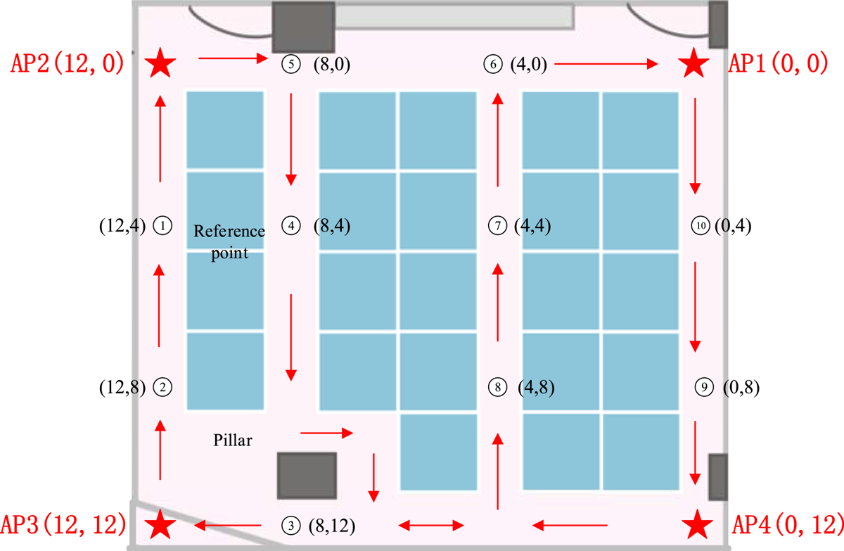
Figure 15. Locations of APs and reference points.
4.4.1. Analysis of real-time performance
We used a Google Pixel 1 phone operating on the newest Android P system as the initiator, then collected RTT data from the four APs in the office using the Wi-Fi ranging API. All the APs had fixed the initial clock deviation and modified the initial clock deviation defined in Equation (5) by subtracting the corresponding initial clock deviation parameters from each AP. We then estimated the maximum real-time sampling rate of RTT data from multiple APs which can truly get in case of 2·4 GHz, 20 MHz, and estimated the stability of the data under different sampling rates. We began with a sampling rate of 0·5 Hz, then improved the sampling rate to 10 Hz, choosing reference point 7 (see 4.4.2 below) as the data collection point, calculated the maximal sampling rate actually achieved after removing the abnormal measured values. The results are shown in Figure 16.

Figure 16. Analysis of continuity and stability of RTT data: (a) data collected from AP1, (b) data collected from AP2, (c) data collected from AP3, (d) data collected from AP4.
It can be observed in Figure 16 that improving the speed of sending the FTM ranging request does not positively correlate with the actual sampling rate. The success rate of sampling significantly declined when the sampling rate was improved to higher than 5 Hz and the average ranging error also increased when the sampling rate was higher than 3 Hz.
After comprehensively considering the real-time performance and stability of the measured data, we chose 3 Hz as the sampling rate used. We also found a few extreme values such as ‘ ${\rm distance}=2\ast 10^{5}\, {\rm m}$’ or zero value, which can be eliminated by the threshold set in advance.
4.4.2. Estimation of FTM-based indoor localisation
We evaluated the accuracy of indoor localisation after estimating the real-time ranging performance and chose the Wi-Fi FTM sampling rate as 3 Hz. The location of the mobile phone can be calculated using real-time RTT information and the locations of the fixed APs deployed in the office. We began the experiment in a typical indoor environment (15 m * 15 m) as the test scenario with typical causes of NLOS and multipath propagation, such as glass, partitions, and two wall columns. We fixed four APs in the office and ensured that the Wi-Fi signal covered the whole area. The position of each AP is show in Figure 15.
The calibrated RTT data acquired from the deployed APs could still be affected by NLOS and multipath propagation without the ranging model. We choose 10 reference points to evaluate the accuracy of the proposed Wi-Fi ranging model. The location of each reference point is shown in Figure 15. AP3 was sometimes obscured by the pillar, causing NLOS error. The Google Pixel 1 phone was set on a 1·5 m high stand. With a sampling rate of 3 Hz, we collected data for 5 min at each reference point and calculated the average results. The raw data and processed data, which have subtracted the ground truth distance, are compared in Table 2.
Table 2. Comparison of ranging error before and after using ranging model.

It can be observed in Table 2 that the obscured AP3 caused extra ranging error at reference points 3, 8, 9 and 10 because of NLOS, while the proposed Wi-Fi ranging model can effectively improve the ranging accuracy of Wi-Fi FTM when direct transmission path is lacking. The KF can further reduce the Gaussian noise under static condition.
We then used the classical least squares trilateration algorithm (Liu et al., Reference Liu, Darabi, Banerjee and Liu2007) to calculate the real-time 2D position by Google Pixel 1 under dynamic conditions after data calibration and modelling. We set the position coordinate output frequency to 3 Hz and obtained the mean positioning error result by choosing the above 10 reference points which have known 2D position, as shown in Figure 15. The tester began with the location of AP1, and passed in turn through reference points 10, 9, 3, 2, 1, 5, 4, 8, 7, 6 and then returned to the location of AP1; the reference route is shown in Figure 15. The real-time calculated localisation result was recorded when passing each reference point and the test route was repeated 10 times by different people. The average positioning error at each reference point is shown in Figure 17.

Figure 17. Localisation accuracy at each reference point.
It can be observed in Figure 17 that the proposed Wi-Fi ranging model effectively improved the accuracy and stability of Wi-Fi based indoor localisation especially in case of NLOS; the average positioning error is lower than 2·2 m.
5. CONCLUSION
The IEEE802.11 Wi-Fi FTM protocol introduced a new research direction for Wi-Fi based indoor positioning. This paper proposes a framework of Wi-Fi RTT data acquisition and processing that can be used for accurate indoor localisation. First, the Wi-Fi RTT ranging system containing responders and initiators that support the Wi-Fi FTM protocol was built up. Then the initial and random clock deviation of the RTT signal were calibrated and eliminated after data measurement and pre-processing. A real-time Wi-Fi ranging model was proposed to estimate the error caused by NLOS and multipath propagation. After that, a rectangular working office wasselected as indoor evaluation site and four APs were deployed at different locations in the office. Real-time RTT data from these APs was acquired by an Android P-based Google Pixel 1 phone and the least squares trilateration algorithm was used to obtain the real-time 2D position.
The whole framework and experiment presented in this paper shows that metre-level RTT ranging results can be obtained in the LOS condition using large bandwidth, and accurate localisation results can be achieved within 2·2 m. With the expansion of hardware functions, more and more Wi-Fi chipsets in mobile devices are expected to support large bandwidth – some can reach 160 MHz or more –, which brings an increasing accuracy of Wi-Fi ranging and Wi-Fi FTM-based indoor localisation. Subsequent to the work presented in this paper, the authors will continue with research on minimising the effect of multipath and NLOS through hardware and algorithms. The aim is to realise a universal localisation algorithm that can adapt to different indoor environments by merging multiple sources of information, such as RSSI, AOA and CSI, and achieve metre-level indoor localisation accuracy.
ACKNOWLEDGEMENTS
This work was supported by the National Key Research and Development Program of China (grant no. 2016YFB0502200 and 2016YFB0502201) and the NSFC (grant no. 91638203), Innovative Team Program funded by Hubei Province (grant no. 2018CFA007).


