


1. INTRODUCTION
Tunnel bow thrusters have been applied on commercial ships since the early 1950s to enhance their manoeuvrability during mooring operations and whilst they are underway at slow speed. A ship's speed through the water is a relevant factor in the performance of these Auxiliary Propulsion Units (APU). The phenomenon of the decrease in their effectiveness with slow speed ahead is a well-known problem to the shiphandler and has been subject of many experimental studies by hydrodynamic researchers trying to find the root of the reasons for this detrimental effect. The aim of such research is to determine solutions that would improve their effectiveness. Extensive model tests and theoretical approaches available in many papers have contributed to a better understanding of the problem and enabled designers to provide better optimum tuning for these APUs. The most evident reason for the ship handler is the position of the peripatetic pivot point of a ship in this condition. But there are other more important hydrodynamic phenomena derived from the interaction between the tunnel bow thruster and the hull that contribute to generate this detrimental effect.
2. THE POSITION OF THE PIVOT POINT
Knowledge about the location of the ship's peripatetic pivot point in each situation is a basic requirement for the ship handler to understand how and why the ship behaves in a certain way. Such knowledge will enable him to foresee the effects of the forces present on the ship, with the purpose of carrying out the manoeuvres safely.
The study of the peripatetic pivot point surpasses the content of this paper and it represents a matter that is considered in all manuals about ship handlingFootnote 1. Suffice to say in relation to the operation of a tunnel bow thruster at slow speed ahead, that one of the reasons it decreases its effectiveness is determined by the small turning arm generated, contributing to a small turning moment. In general, we can consider that the pivot point of a ship on even keel with straight speed ahead is located approximately 1/4 the length of the ship from the bow; it is clear that in this situation the distance to the point of application of the thrust (turning arm) is relatively small and, as a result, this it is one of the reasons for the decrease of its effectiveness with slow speed ahead (see Figure 1).

Figure 1. Small turning moment of the tunnel bow thruster with straight speed ahead. Drawing: author.
3. THE INTERACTION BETWEEN THE TUNNEL BOW THRUSTER AND THE HULL
Beyond the pivot point position, the reduction in efficiency of a tunnel bow thruster of a ship with slow speed ahead is a hydrodynamic problem that contains different aspects that can be considered as a whole within the interaction of APU with the hull. The cross flow condition of the jet thruster and the adjacent outboard water flow determine the hydrodynamic phenomenon that results in the decrease of the turning moment. In this section, the most prominent aspects that determine the design to achieve optimum effectiveness are analysed.
3.1. The increase of hydrodynamic ship resistance
This is a very well known phenomenon generated by the vortices that are formed and that absorb energy from the adjacent external flow on the jet exit sideFootnote 2. The smaller the diameter of the tunnel, the less resistance it will cause when underway. In particular, this dissipation of energy is caused by an expansion of the jet exit side surrounded by vortices (on the jet entrance side, a jet contraction is formed that generates favourable suction fields and flow acceleration). Its value is approximately in cube proportion to the diameter of the tunnel and the turbulences generated around the tunnel entrances represent a problem that is directly affected by its dimensions and indirectly by the diameter of the propeller and its rate of revolution in order to achieve an optimum design in each particular case. In fact (see Figure 2), the net transverse force generated by the bow thruster will be the result of the algebraic addition of the jet reaction force (R) and the forces of interference that are formed respectively on the jet entrance side (IF), which is beneficial and on the jet exit side (ID), which is detrimental.

Figure 2. Increase of tunnel resistance as a result of energy absorption of a twin vortex generated on the tunnel exit side where an expansion of the jet surrounding those vortices is produced. Drawing: author.
3.2. The adjacent flow on each of the hull's sides of the ship
The shape of the ship's hull where a tunnel bow thruster is installed has a significant influence on the performance at speeds ahead and astern. Ideally the flow of water adjacent to the tunnel on both hull's sides should flow perpendicular to it, which determines that at design level, the tunnel should be located in an area where the sides of the ship are parallel. Any angle θ that is bigger than 90° between the side of the ship and the tunnel has a detrimental effect, especially in the entrance flow to the tunnel due to its strangulation, to the formation of turbulences and to a non homogeneous flow of the tunnel (improved in the longest superior part and distorted in the shortest inferior part), giving rise to overloads as a whole; these overloads are due to unstable flow conditions on the jet entrance side.
This need to reduce the overloads generated at the entrance of the tunnel is difficult to achieve at design level due to the sharp bows of many V-shaped ships where the sidewalls are not parallel, excluding those ships that have a bulbous bow. Bearing in mind that, with the purpose of endowing it with a good turning arm, the tunnel should be located as close as possible towards the bow, there is a compromise between the two alternatives.
3.3. Different fields of pressure around the entrance and exit of the tunnel
English, J.W. (Reference English1963) investigated the transverse thrust generated by a tunnel bow thruster with ship's speed ahead. From his work, he came to the conclusion that a reduction of the transverse thrust at slow ship speed ahead took place in comparison with the zero ship speed condition and that this reduction was bigger as the speed ahead was increased until reaching a certain speedFootnote 3 from which a gradual improvement took place although, in any event, smaller than at zero ship speed condition. From zero ship speed up to between five and seven knots, the transversal thrust of bow thrusters decreases considerably and increases thereafter without reaching the full thrust achieved at zero ship speedFootnote 4. This reduction in the performance of the tunnel bow thruster was attributed to the change in the distribution of the pressureFootnote 5 that originates mainly from the deflection on the exit side of the impeller jet as it becomes increasingly oriented parallel to the ship, due to the combined movements of the ship when the ship handler uses the tunnel bow thruster in this condition (forward speed – translational motion – and simultaneous lateral and yaw motions – rotational motion, both of them generated by the action of the bow thruster). Regarding this matter, the experimental works carried out by Brix, J.E. et al. (Reference Brix and Troup1973) that confirmed English's investigations are also of singular relevance.
To sum up, the formation of different fields of pressure around the entrance and exit of the tunnel constitutes one of the main reasons for the decrease in the effectiveness of a tunnel bow thruster with slow speed ahead and is due to an unfavourable pressure redistribution over the ship's hull near the inlet and outlet cross sections of the tunnel due to the ship's motion. (See Figure 3).

Figure 3. Different fields of pressure around a tunnel bow thruster with slow speed ahead. Drawing: author.
In this situation, researchers agree on identifying the four numbered areas of different pressure around the tunnel shown in Figure 3:
1. Downstream of the jet exit side (field 1) a negative pressure region, which is induced by a twin vortex behind the deflected jet, is generated.
2. Downstream of the jet entry side (field 2) there is a positive pressure area induced by the sinking effect of the propeller.
3. Upstream of the jet exit side (field 3) there is a positive pressure area generated by the relaxation of flow ahead of the jet outflow.
4. Upstream of the jet entry side (field 4) there is a negative pressure area generated by the acceleration of the inflow.
Fields of pressure 1 and 2 have a detrimental character while fields 3 and 4 are beneficial. The field of negative pressure formed downstream of the jet entry side prevails over all the other ones and, as a consequence, a force of resulting suction is generated that is detrimental for the effectiveness of the propeller since it opposes its thrust.
Concerning the formation of these different fields of pressure in both sides of the ship around the tunnel, Ridley (Reference Ridley1971), demonstrated that when the ship has speed astern, a reversal of fields of pressure takes place and that the reduction of the turning moment is smaller in this supposition than when the ship has slow speed ahead. In conclusion, a smaller suction force takes place since the area of negative pressures is less extensive and the area of positive pressures is relatively high in comparison with the slow speed ahead condition. All these conclusions were confirmed later in experimental works by Brix (Reference Brix1993 p. 21) and Nienhuis (Reference Nienhuis1992 p. 128).
Although not directly related with the content of this paper, it is interesting to note that by contrast with the tunnel bow thruster, the effectiveness of a tunnel aft thruster is not hampered by the motion of the ship and in certain cases it may even improveFootnote 6.
4. DESIGN RECOMMENDATIONS
In general, as a result of the previous considerations the following design recommendations can be extracted:
• With the purpose of avoiding asymmetric thrust, the bow thruster should be installed ideally in the centre of the tunnel, although in shorter tunnels the propeller must be located eccentrically due to the length of the gearbox.
• To avoid overloads, the tunnel should be located in an area where the hull sides of the ship are the most parallel i.e. the optimum tunnel exit angle should be oriented 90° to the adjacent hull.
• With the purpose of endowing the propeller with the biggest possible turning arm, it should be installed at the end of the bow and, as we have seen, this demand must be combined with the previous recommendation. This fact often constitutes a situation of compromise for the designer due to the sharp bows of V-shaped ships.
• The optimum tunnel length is approximately 2D (with D the propeller diameter)Footnote 7. A long tunnel causes increased friction losses, and too short a tunnel causes losses due to turbulence.
• Regarding the vertical location of the tunnel, it should be installed as deeply as possible in order to avoid cavitations, but with the limit of approximately 1·5D over the keel in order to avoid circulation around it.
• The installation of protection grids at the tunnel exits in both ship hull sides is recommended with the purpose of reducing the tunnel resistance to suppress any vortex generation by disturbing the exchange of energy absorbed by the generation of vortices in another case. The most effective configuration that has been revealed consists of four flat iron bars (depending on the diameter of the tunnel, it can be up to seven) to be fitted vertically (i.e. perpendicularly) to the local direction of the entrance water flowFootnote 8 which, if it is unknown (see Figure 4), α=15° may be applied (the determination of α in each particular case should be found in a paint test) and three to four horizontal round bars fixed perpendicularly to the flat bars. Another configuration of the protection grids proposed by Brix, but that has had less implementation, are concentric rings instead of the flat iron barsFootnote 9. The inconveniences that involve the installation of protection grids are:
∘ They restrict the water flow.
∘ An overload may occur since the jet is throttled.
∘ Frictional losses have to be taken into account.
∘ In ice, the bars should be strengthened to allow for both static and dynamic ice pressure. In general grids could be inadvisable in ice operations due to ice blockage within the tunnel and mechanical damage of the protection grid.
• Another function of protection grids is the protection of jet thrusters against mechanical damage.
• The fairings at the tunnel exits are designed to reduce the added resistanceFootnote 10 and this is achieved from a sharp transition between the hull and the tunnel thruster, but this is detrimental to the thruster efficiency. Taking this into account, the designers adopt two basic configurations:
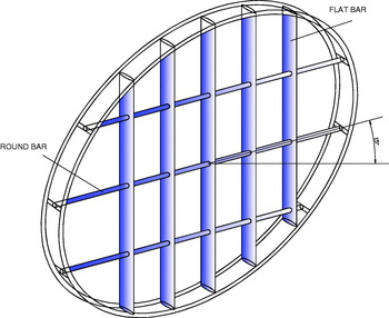
Figure 4. Typical grid construction for a tunnel thruster. Drawing: author.

Figure 5. Left: A typical tunnel bow thruster with a protection grid and a conical fairing at the aft part (source http://en.wikipedia.org). Right: A modern protection grid with a hull-thruster sharp transition (source: author).
5. THE AST AS AN OPTION TO IMPROVE THE PERFORMANCE OF TUNNEL BOW THRUSTERS WITH SLOW SPEED AHEAD
Countermeasures against the reduction of the side force with ship's speeds ahead were developed in the early 1970s when extensive experiments were carried out to overcome this detrimental effect on the tunnel bow thruster performance with the purpose of improving their efficiency in this condition.
One of the best known experimentsFootnote 11 that has enjoyed a bigger implantation was put forward by Brix (Reference Brix and Troup1973), who investigated the use of an AST (also known as a pressure equalising tunnel). The system consists on the incorporation of a passive tunnel of a small diameter aft of the tunnel bow thruster that serves as a conduit. This allows it to equal fields of pressure 1 and 2 (see Figure 3), reducing the resulting suction force that is generated in this way and that has a detrimental effect on the thrust. The difference of the detrimental pressure fields on both sides spreads to be equalled via the AST; thus, a passive water-jet effect is generated that acts in the same sense as the active water-jet effect generated by the bow thruster, and its efficiency increases in this condition.
The AST is placed immediatelyFootnote 12 aft of the tunnel thruster so that the water pressure fields can be equalised when the ship is going ahead. Its diameterFootnote 13 is the smallest possible to permit an effective passive water-jet effect. In Figure 6, a ship at slow speed ahead is represented endowed with a tunnel bow thruster and an AST immediately aft. The tunnel bow thruster is working to provide a rotational moment to port, showing the typical fields of pressure that are generated in this condition and the passive water-jet effect that is originated as a consequence of the incorporation of an AST contributes to increase the active water-jet effect, as it is acting in the same sense.

Figure 6. Sketch of a tunnel bow thruster and an AST with slow speed ahead, showing the pressure fields and the active and passive water-jet effect generated when the thruster is pushing to port. Drawing: author.
In Figure 7, the same ship is shown equipped with an AST, but on this occasion with speed astern. The situation now is different since a variation of the fields of pressure takes place in comparison to when the ship has slow speed ahead. As a conclusion, if the AST is located aft of the tunnel bow thruster, as is normal, it can only have an optimum effect in one direction since, as we can appreciate in this figure, the generated passive water-jet is detrimental to maintaining its efficiency in this situation because this water-jet counters the active cross flow from the bow thruster. Nevertheless, it is very important to notice that in comparison to the previous supposition of a ship with slow speed ahead, the low pressure area of the deflected jet downstream of the jet exit side is less extensive. Therefore, as the resultant suction force is smaller, the detrimental passive water-jet effect generated through the AST is smaller, too. If to this fact we add that the bow thruster has a bigger turning arm (in this condition, the pivot point is located approximately at 1/4 the length of the ship from the stern) and that the speed astern is usually low, it is easy to conclude that the benefits that the AST contributes to the effectiveness of the propeller with slow speed ahead compensate the disadvantage that supposes its installation when the ship has speed astern in excess.

Figure 7. Sketch of a tunnel bow thruster and an AST with speed astern, showing the pressure fields and the active and passive water-jet effect generated when the thruster is pushing to port. Drawing: author.
The improvement of the tunnel bow thruster performance with an AST at slow ship speed can be easily measured by means of comparatively turning tests in model tests. Figure 8 shows some results of a model manoeuvring test carried out by Brix (Reference Brix1993 p 35) with a large model thruster installed in the bulbous bow of a slender twin screw car ferry with and without AST.

Figure 8. Uncorrected results of a turning test in a model test with and without AST of a twin screw ferry with a single bow thruster. Source: Brix, J., Manoeuvring Technical Manual. Drawing: author.
Although they are approximate results, it is worth highlighting the improvement in the efficiency of a bow thruster endowed with an AST when the ship has slow speed ahead and that this improvement starts to decrease from a certain ship's speedFootnote 14. In addition, the fact that with speed astern the AST is detrimental with this disposition although the benefits that it affords with slow speed ahead more than compensate for this disadvantage.
Figure 9 shows a modern tanker ship with an AST to improve the performance of the tunnel bow thruster with speed ahead.
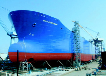
Figure 9. The tanker “Polar Endeavour” (ex “Arco Endeavour”) showing the bow thruster with an AST (a 2207 kW thruster of 2·4 m diameter with a 0·8 m diameter AST). Photograph: author.
6. CONCLUSIONS
A tunnel bow thruster quickly loses its manoeuvring effectiveness as forward ship's speed increases within a slow speed range and many experiments conducted by researchers have contributed to the understanding of this phenomenon. Besides the scarce turning arm with which a tunnel bow thruster counts with slow speed ahead due to the position of the peripatetic pivot point in this condition, the presence of hydrodynamic phenomena have a great relevance to their efficiency.
Being an integral part of the ship hull, it is difficult to distinguish between the aspects that improve the efficiency of the thrusters and the designs which reduce the interaction with the hull. Thus, the shape of the hull-tunnel intersection, the angles between the hull and the tunnel, the tunnel fairings, the tunnel length and diameter, the propeller diameter and rpm's (the bigger they are, the higher the friction losses will be), all influence the tunnel efficiency and, in consequence, the APU should be tuned for each particular case, keeping in mind all the previous factors.
The most important hydrodynamic phenomenon is the one formed by the different fields of pressure generated in the tunnel entrance and exit of the jet thruster. They are all detrimental because the integrated forces present are acting in a direction contrary to the thrusters when the ship has slow speed ahead, and the AST is nowadays the most advisable design option because it generates a passive water jet effect that acts in the same sense as the active water jet effect of the bow thruster.
In short, the AST allows the tunnel bow thruster to improve efficiency at slow forward speeds within the speed range where the main rudder lift is small (let us remember that the rudder is a hydrodynamic foil that acts as a ship's typical passive control surface, and as such, it depends on the relative motion of the water over its surface to produce manoeuvring forces that vary with the square of the ship's speed), thus filling this gap to produce effective manoeuvring forces, enhancing the ship's manoeuvrability.


