1. INTRODUCTION
The pseudorange and carrier phase measurements in Global Navigation Satellite Systems (GNSSs) contain various types of errors, among which multipath error, ionospheric errors and other inherent errors are the main sources affecting satellite navigation and positioning accuracy. Much work has been carried out to separate and eliminate these errors.
Anisotropic ionospheric plasma effects in phase and signal delays at high frequencies can be represented as a series of rapidly decreasing data in an inverse function of frequency (Bassiri and Hajj, Reference Bassiri and Hajj1992; Kim and Tinin, Reference Kim and Tinin2007a). The delays caused by ionospheric plasma on pseudorange and carrier phase measurements are equal in size and opposite in direction, which is different from multipath effect.
Multipath effects can be investigated through a combination of code range and carrier phase observations. Certain characteristics of GNSS code observations can be analysed in a combination of single-frequency code and dual-frequency phase observations, which is called multipath observation. The multipath combination of code and carrier observations has been employed to investigate multipath in a time series (Estey and Meertens, Reference Estey and Meertens1999; Xia et al., Reference Xia, Liu, Zhang and Deng1999; Zhang and Ding, Reference Zhang and Ding2013). Multipath observation values may be affected by the characteristics of the signal and the sensitivity of the receiver and antenna, which was discussed in detail in Simsky (Reference Simsky2006). The multipath combination contains both code and carrier multipaths, and combinations of hardware delay and thermal noise (De Bakker et al., Reference De Bakker, Tiberius, Marel and Bree2012). Time series multipath observations are usually used to detect and describe code multipath effects. The Global Positioning System (GPS), BeiDou System (BDS) and Globalnaya Navigazionnaya Sputnikovaya Sistema (GLONASS) also use multipath observations to monitor their multipath effects (Odolinski et al., Reference Odolinski, Teunissen and Odijk2015). The multipath combinations of BDS observables contain not only real multipath effects but also other multipath-like biases that are caused by reflections of the satellite components or internal hardware delays, which are hard to verify but do exist (Zhao et al., Reference Zhao, Wang, Liu, Hu, Dai and Liu2016). Examples of multipath analysis of BDS can be found in Shi et al. (Reference Shi, Zhao, Hu and Liu2013) in precise positioning with accurate ephemeris data and Wang et al. (Reference Wang, de Jong, Zhao, Hu and Guo2014) in code observation multipath analysis of BDS geostationary satellites.
There is a close relationship between the elimination of multipath and ionospheric errors, which will degrade the accuracy of positioning. The phase multipath is known to be less than π/2 (roughly less than 5 cm for the GPS L1 signal), while the second- and higher-order ionospheric terms can be up to several centimetres (Fritsche et al., Reference Fritsche, Dietrich, Knöfel, Rülke and Vey2005). There was analysis of the multipath impact on positioning in Zhang et al. (Reference Zhang, He, Tang, Shen, Chen, Sun, Jiao, Wu and Shi2013) and on dual-frequency ionospheric delay corrections in Zhao et al. (Reference Zhao, Zhao, Zhao, Zhao, Sun, Jiao, Wu and Shi2013b). With the demand of high accuracy positioning, traditional dual-frequency observation cannot eliminate the higher-order ionospheric errors. Thus, with the increasing number of GNSS frequencies, researchers have explored multi-frequency GNSS combination measurement. Bassiri (Reference Bassiri1990) and Wang et al. (Reference Wang, Wu, Zhang and Meng2005) have suggested the use of a GNSS triple-frequency code-multipath combination to eliminate the second order ionospheric error. However, considering the four BDS frequencies, there exist various observable combinations.
Recently, researchers have found some other errors including multipath-like biases and hardware delay in carrier multipath (Zhao et al., Reference Zhao, Wang, Liu, Hu, Dai and Liu2016). The non-optimal combination will amplify these errors, making it hard to investigate the real code multipath effect. With the improvement of positioning accuracy, the traditional method cannot distinguish the multipath, the second order ionospheric error and the biases from the main satellite signal. To solve this problem, we have developed an optimal method for multi-frequency GNSS code-multipath combination measurement by considering the different characteristics. The optimum combination solution can eliminate the first order and second order ionospheric error with minimum carrier errors and biases introduced. In the method proposed, the second order ionospheric error, multipath error and the bias from satellites can be separated by using the optimum combinations.
Using BDS as an example of a GNSS, we first analyse the relationship between the GNSS observation and the ionospheric error. Then, with regard to the first order ionospheric error, the optimum combination solution is calculated by triple-frequency code-multipath combination with one degree of freedom and compared with a dual-frequency combination. Next, as for the second order ionospheric error, the optimum combination of quad-frequencies is calculated and compared with the triple-frequency combination, which minimises the carrier phase measurement error. We have verified the optimisation algorithms by exploiting three-frequency data from a BDS International GNSS Service (IGS) station and a city canyon, as well as the actual BDS observation data collected from four frequencies. Finally, the optimum and the non-optimum combinations are analysed and compared, which separates the multipath on the code phase and the error or biases on the carrier phase. The optimum combination provides the best way to evaluate the code multipath measurements of future multi-frequency BDS and can be extended to other future GNSSs.
2. GNSS OBSERVABLES MODEL
The GNSS code observables and carrier phase measurements from satellite p on the three frequencies (i, j, k) are as follows (Wang and Rothacher, Reference Wang and Rothacher2013):
 $$\left\{\matrix{L_i^p =\varphi_i^p =\rho^p+c\lpar {dt-dT^p} \rpar +I_{_{\varphi i} }^p +T_i^p+ML_i +\lambda_i N_i +\varepsilon_i \hfill \cr L_j^p =\varphi_j^p =\rho^p+c\lpar {dt-dT^p} \rpar +I_{_{\varphi j} }^p +T_i^p+ML_j +\lambda_j N_j +\varepsilon_j \hfill \cr L_k^p =\varphi_k^p =\rho^p+c\lpar {dt-dT^p} \rpar +I_{_{\varphi k} }^p +T_i^p+ML_k +\lambda_k N_k +\varepsilon_k \hfill \cr P_i^p =\rho^p+c\lpar {dt-dT^p} \rpar +I_{\rho i}^p +T_i^p+MP_i +\delta_i \hfill \cr P_j^p =\rho^p+c\lpar {dt-dT^p} \rpar +I_{\rho j}^p +T_i^p+MP_j +\delta_j \hfill \cr P_k^p =\rho^p+c\lpar {dt-dT^p} \rpar +I_{_{\rho k} }^p +T_i^p+MP_k +\delta_k \hfill }\right. $$
where  $L_{i}^{p}$ represents carrier phase output of the receiver from the satellite p on the i-th frequency in metres;
  $P_{i}^{p}$ and
  $\varphi _{i}^{p}$ represent code and carrier phase observable output by the receiver from the satellite p on the i-th frequency in metres; ρ p represents the distance between the receiver and the satellite p; dt and dT p represent the clock errors of the receiver and the satellite p;
  $I_{\varphi i}^{p} $,
  $I_{\rho i}^{p}$ represent the ionospheric delay on code and carrier phase on the i-th frequency;
  $T_{i}^{p}$, ε i, δ i represent the tropospheric delay, carrier biases or noise error and code noise error on the i-th frequency and MP i, ML i represent the multipath error on code and carrier phase error including hardware delay and multipath-like biases. N i represents the integer ambiguity of the phase measurement in cycles.
When considering the higher order ionospheric delay component, we can derive the ionospheric code delay I ρ and the carrier delay I φ as (Feng and Li, Reference Feng and Li2008):
 $$\left\{\matrix{I_\rho =\displaystyle{{A_1} \over {f^2}}+\displaystyle{{A_2} \over {f^3}}+\cdots =\sum_{i=1}^n {\displaystyle{{A_i} \over {f^{i + 1}}}} \hfill \cr I_\varphi =-\displaystyle{{A_1} \over {f^2}}-\displaystyle{{A_2} \over {2f^3}}-\cdots =-\sum_{i=1}^n {\displaystyle{{A_i} \over {if^{i + 1}}}} \hfill \cr}\right. $$
where A i is the coefficient of the i-th order which represents the relationship between carrier and code.
3. EXPERIMENT ENVIRONMENT AND DATA SET
3.1. Observations from IGS station
We calculated the multipath time series from the observations of BeiDou B1I, B2I and B3I detected at the static observatory (CUT0) in Perth, Australia on 19 May 2013. The IGS observatory outputs the code phase and carrier phase observations every 30 s in all three frequencies.
3.2. Observations from city canyon
The tri-frequency data from a city canyon environment were collected from a small antenna on the roof top of the new main building at Beihang University, as shown in Figure 1. The observations were recorded every 1 s.

Figure 1. The city canyon environment.
3.3. Data sampling equipment
The four frequencies of BDS data were collected from the small antenna at Beihang University on 15 April 2016. The BeiDou satellite PRN 32 was taken as an example. The flow chart for data processing is shown in Figure 2. The BDS signal was processed by down conversion, filtering and analogue to digital sampling. The digital intermediate frequency signals were collected and stored in the form of PC files. The data were collected from the same antenna, driven by the same atomic clock on the four frequencies of B1/B2a/B2b/B3 in a synchronised sampler. A software receiver was used to extract the code phase and carrier phase measurements, which was later calculated by the triple-frequency and quad-frequency combination methods.

Figure 2. Flow chart of four-frequency data analysis.
Currently, five navigation signals are broadcast on BDS B1I, B1C, B2a, B2b (or B2I) and B3I frequencies (Feng et al., Reference Feng2008). Our study takes BeiDou satellite navigation system as an example, which also can be extended to future GPS and Galileo systems. The main frequency values of BDS are shown in Table 1.
Table 1. BDS signal frequency allocation

4. FIRST-ORDER IONOSPHERIC ERROR ELIMINATION METHOD
In order to eliminate the first order ionospheric error, we calculate the dual-frequency and the optimum solution of triple-frequency code-multipath combination methods. The comparison of these two methods is discussed in this section.
4.1. Dual-frequency code-multipath combination method
Dual-frequency code-multipath phase measurement provides a method to evaluate multipath effects on code measurements. Dual-frequency code-multipath combination can be written as (Wanninger and Beer, Reference Wanninger and Beer2014):
 $$M\lpar P_i \comma \; L_i \comma \; L_j \rpar =c_1 \cdot P_i +c_2 \cdot L_i +c_3 \cdot L_j $$
where P i, L i and L j are the code and carrier phase observations on i-th and j-th frequencies of a satellite, and c 1, c 2 and c 3 are constant coefficient terms. To obtain geometry-independent observables, we set:
 $$c_1 +c_2 +c_3 =0 $$
In order to obtain the ionosphere independent observables, the first-order ionospheric error can be eliminated by the following equation:
 $$\displaystyle{{c_2-c_1} \over {f_i^2 }}+\displaystyle{{c_3} \over {f_j^2 }}=0 $$
where f i and f j are the i-th and j-th frequencies. Taking into account the structure of the code-multipath combination observations:
 $$\left\{\matrix{c_1 =1 \hfill \cr c_2^2 +c_3^2 =\Omega \hfill \cr }\right.\lpar \Omega\hbox{ as constant}\rpar $$
where Ω is defined as the carrier amplifier factor, indicating an amplified ratio of the error and noise in combination equations. A unique solution can be obtained by Equations (4) and (5), shown as:
 $$\left\{\matrix{c_2 = \displaystyle{{f_j^2 + f_i^2 } \over {f_j^2 -f_i^2 }} \hfill \cr c_3 = \displaystyle{{2f_j^2 } \over {f_i^2 -f_j^2}}\cr} \right. $$
When using two BDS frequencies, the constant coefficient terms c 2, c 3 and the amplifier factor Ω can be obtained as:
 $$\left\{\matrix{{M\lpar P_1 \comma \; L_1 \comma \; L_2 \rpar =P_1 -3{\cdot}974L_1 +2{\cdot}974L_2 } & {\Omega =24{\cdot}64} \hfill \cr {M\lpar P_1 \comma \; L_1 \comma \; L_3 \rpar =P_1 -4{\cdot}887L_1 +3{\cdot}887L_3 } & {\Omega =38{\cdot}99} \hfill \cr {M\lpar P_2 \comma \; L_2 \comma \; L_3 \rpar =P_2 +20{\cdot}179L_2 -21{\cdot}179L_3 } & {\Omega =855{\cdot}75} \hfill \cr {M\lpar P_2 \comma \; L_2 \comma \; L_1 \rpar =P_2 +3{\cdot}974L_2 -4{\cdot}974L_1 } & {\Omega =40{\cdot}54} \hfill \cr {M\lpar P_3 \comma \; L_3 \comma \; L_1 \rpar =P_3 +4{\cdot}887L_3 -5{\cdot}887L_1 } & {\Omega =58{\cdot}55} \hfill \cr {M\lpar P_3 \comma \; L_3 \comma \; L_2 \rpar =P_3 -20{\cdot}179L_3 +19{\cdot}179L_2 } & {\Omega =775{\cdot}03} \cr}\right. $$
The dual-frequency code-multipath combination can be expressed as:
 $$M\lpar P_i \comma \; L_i \comma \; L_j \rpar =\lpar MP_i +c_2 ML_i +c_3 ML_j \rpar +\lpar \delta _i +c_2 \varepsilon _i +c_3 \varepsilon _j\rpar $$
When ML is neglected, the MP combination only reflect the code multipath. However, when ML cannot be neglected, Ω reflects the amplifier ratio of the carrier error and bias.
The above dual-frequency code-multipath combination can eliminate the first-order ionospheric error. Because the frequency difference between B2I and B3I is small, the amplifier factor of this combination is increased to 855·75, which will introduce more error to the multipath observation measurement.
4.2. Triple-frequency code-multipath combination method
The triple-frequency code-multipath phase combination is similar to the dual-frequency combination. A combination of three frequencies is used to eliminate the first order ionospheric error. The triple-frequency code-multipath combination can be written as:
 $$M1\lpar P_i \comma \; L_i \comma \; L_j \comma \; L_k \rpar =c_1 \cdot P_i +c_2 \cdot L_i +c_3 \cdot L_j +c_4 \cdot L_k $$
where P i, L i, L j and L k are the code and carrier phase observations on i-th, j-th and k-th frequencies of a satellite; c 1, c 2, c 3andc 4 are constant coefficient terms. To obtain geometry-independent observables:
 $$c_1 +c_2 +c_3 +c_4 =0 $$
To obtain the ionosphere independent observables, the first-order ionospheric error can be eliminated by the following equation:
 $$\displaystyle{{c_2-c_1} \over {f_i^2 }}+\displaystyle{{c_3} \over {f_j^2 }}+\displaystyle{{c_4} \over {f_k^2 }}=0 $$
where f i, f j and f k are the i-th, j-th and k-th frequencies. Taking into account the structure of the code-multipath combination observations:
 $$\left\{\matrix{c_1 =1 \hfill \cr c_2^2 +c_3^2 +c_4^2 =\Omega \hfill \cr } \right.\lpar \Omega\hbox{ as constant}\rpar $$
The triple-frequency multipath combination can be expressed as:
 $$M1\lpar P_i \comma \; L_i \comma \; L_j \comma \; L_k \rpar =\lpar MP_i +c_2 ML_i +c_3 ML_j +c_4 ML_k \rpar +\lpar \delta _i +c_2 \varepsilon _i +c_3 \varepsilon _j +c_4 \varepsilon _k \rpar $$
If the amplifier factor Ω is large, the error and bias on the carrier phase will be amplified to a large extent, which will greatly influence the code multipath combination.
If only Equations (11) and (12) are used to calculate the c 2, c 3, c 4 coefficients, there are infinite solutions. When considering the minimum Ω as the optimal condition, the solution  $\mathop {\arg \min }\limits_{\Omega} \lpar c_{2} \comma \; c_{3} \comma \; c_{4} \rpar $ can be derived as:
 $$\left\{\matrix{c_2 = \displaystyle{{-\lpar f_i^4 f_k^4 + f_i^4 f_j^4 -2f_j^4 f_k^4 \rpar } \over {\lsqb f_i^4 {\lpar f_j^2 -f_k^2 \rpar }^2 + f_k^4 {\lpar f_i^2 -f_j^2 \rpar }^2 + f_j^4 {\lpar f_i^2 -f_k^2 \rpar }^2\rsqb }} \hfill \cr c_3 = \displaystyle{{-\lpar f_j^4 f_i^4 + f_j^4 f_k^4 -2f_i^4 f_k^4 \rpar } \over {\lsqb f_i^4 {\lpar f_j^2 -f_k^2 \rpar }^2 + f_k^4 {\lpar f_i^2 -f_j^2 \rpar }^2 + f_j^4 {\lpar f_i^2 -f_k^2 \rpar }^2\rsqb }} \cr c_4 =\displaystyle{{-\lpar f_k^4 f_i^4 + f_k^4 f_j^4 -2f_i^4 f_j^4 \rpar } \over {\lsqb f_i^4 {\lpar f_j^2 -f_k^2 \rpar }^2 + f_k^4 {\lpar f_i^2 -f_j^2 \rpar }^2 + f_j^4 {\lpar f_i^2 -f_k^2 \rpar }^2\rsqb }} \hfill \cr } \right. $$
For BDS, the relationship among the constant coefficient terms c 2, c 3, c 4 and the amplifier factor Ω can be obtained as:
 $$\left\{\matrix{{M\lpar P_1 \comma \; L_1 \comma \; L_2 \comma \; L_3 \rpar =P_1 -4{\cdot}167L_1 +2{\cdot}348L_2 +0{\cdot}818L_3 } & {\Omega =23{\cdot}54} \hfill \cr {M\lpar P_2 \comma \; L_2 \comma \; L_1 \comma \; L_3 \rpar =P_2 +3{\cdot}101L_2 -5{\cdot}242L_1 +1{\cdot}141L_3 } & {\Omega =38{\cdot}40} \hfill \cr {M\lpar P_3 \comma \; L_3 \comma \; L_1 \comma \; L_2 \rpar =P_3 +1{\cdot}065L_3 -4{\cdot}990L_1 +2{\cdot}924L_2 } & {\Omega =34{\cdot}58} \hfill \cr }\right. $$
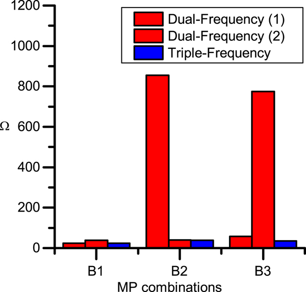
Compared with Equation (8), the amplifier factor Ω of the triple-frequency combinations are reduced by 4·46%, 39·63%, 95·51%, 5·27%, 40·93% and 95·54% of the corresponding dual-frequency combinations. The comparison histogram is shown in Figure 3.

Figure 3. Comparison of Ω between dual-frequency and triple-frequency combinations.
5. SECOND-ORDER IONOSPHERIC ERROR ELIMINATION METHOD
The traditional ionospheric error correction method ignores the second order and higher-order terms of propagation delay, because the method cannot eliminate the error introduced by the higher order terms. Taking the higher-order terms into account, the code phase and carrier phase of ionospheric delays are not a simple opposite relationship. By using the four BDS frequencies, the optimum combination solution can eliminate the first and second order ionospheric errors with minimum error introduced.
5.1. Triple-frequency code-multipath combination method
Considering the triple-frequency code-multipath combination has eliminated the first and second order ionospheric error simultaneously, the equations are shown as:
 $$M2\lpar P_i \comma \; L_i \comma \; L_j \comma \; L_k \rpar =c_1 \cdot P_i +c_2 \cdot L_i +c_3 \cdot L_j +c_4 \cdot L_k $$
 $$c_1 +c_2 +c_3 +c_4 =0 $$
 $$\displaystyle{{c_2-1} \over {f_i^2 }}+\displaystyle{{c_3} \over {f_j^2 }}+\displaystyle{{c_4} \over {f_k^2 }}=0 $$
 $$\displaystyle{{c_2-2} \over {f_i^3 }}+\displaystyle{{c_3} \over {f_j^3 }}+\displaystyle{{c_4} \over {f_k^3 }} = 0 $$
 $$\left\{\matrix{ c_1 =1 \hfill \cr c_2^2 +c_3^2 +c_4^2 =\Omega \cr} \right. \lpar \Omega\hbox{ as constant}\rpar $$
Three BDS frequencies are used in these equations, where the coefficient terms c 2, c 3, c 4 and the amplifier factor Ω can be obtained as:
 $$\left\{\matrix{{M\lpar P_1 \comma \; L_1 \comma \; L_2 \comma \; L_3 \rpar =P_1 -8{\cdot}133L_1 -10{\cdot}573L_2 +17{\cdot}705L_3 } & {\Omega =491{\cdot}40} \hfill \cr {M\lpar P_2 \comma \; L_2 \comma \; L_1 \comma \; L_3 \rpar =P_2 +24{\cdot}778L_2 +1{\cdot}412L_1 -27{\cdot}190L_3 } & {\Omega =1355{\cdot}40} \hfill \cr {M\lpar P_3 \comma \; L_3 \comma \; L_1 \comma \; L_2 \rpar =P_3 -14{\cdot}645L_3 -1{\cdot}300L_1 +14{\cdot}945L_2 } & {\Omega =439{\cdot}52} \hfill \cr }\right. $$
These formulae have eliminated the second-order ionospheric error, but the coefficient in front of the carrier phase is large. If the factor of the carrier is large, it will induce more inherent error to the combination. In Equation (22), the Ω increases from 12·71 to 35·30 times more than those of Equation (16). As a result, in order to eliminate the second-order ionospheric error with the minimum error on the carrier phase, it is suggested to use a fourth frequency.
5.2. Quad-frequency code-multipath combination method
The quad-frequency code-multipath combination can be written as:
 $$M=c_1 \cdot P_i +c_2 \cdot L_i +c_3 \cdot L_j +c_4 \cdot L_k +c_5 \cdot L_z $$
where P i, L i, L j, L k and L z are the code and carrier phase observations of a satellite at a specific frequency and c 1, c 2, c 3, c 4, c 5 are constant coefficient terms. We assume that L i, L j, L k and L z are uncorrelated. To obtain geometry-independent observables, we get:
 $$c_1 +c_2 +c_3 +c_4 +c_5 =0 $$
To obtain the ionosphere independent observables, the first-order and second-order errors can be eliminated by the following equations:
 $$\displaystyle{{c_2-c_1} \over {f_i^2 }}+\displaystyle{{c_3} \over {f_j^2 }}+\displaystyle{{c_4} \over {f_k^2 }}+\displaystyle{{c_5} \over {f_z^2 }} = 0 $$
 $$\displaystyle{{c_2-2c_1} \over {f_i^3 }}+\displaystyle{{c_3} \over {f_j^3 }}+\displaystyle{{c_4} \over {f_k^3 }}+\displaystyle{{c_5} \over {f_z^3 }}=0 $$
where f i, f j, f k and f z are the i-th, j-th, k-th and z-th frequencies. Taking into account the structure of the code-multipath combination observations:
 $$\left\{\matrix{c_1 =1 \hfill \cr c_2^2 +c_3^2 +c_4^2 +c_5^2 =\Omega \hfill \cr }\right. \lpar \Omega \hbox{ as constant}\rpar $$
 Similarly, to minimise the error contained in carrier, the minimum Ω is considered as the optimal condition. Then the solution  $\mathop {\arg \min }\limits_{\Omega} \lpar c_{2} \comma \; c_{3} \comma \; c_{4} \comma \; c_{5} \rpar $ can be derived as:
 $$\left\{\matrix{{M\lpar P_1 \comma \; L_1 \comma \; L_{2a} \comma \; L_{2b} \comma \; L_3 \rpar =P_1 -7{\cdot}726L_1 -7{\cdot}056L_{2a} +1{\cdot}758L_{2b} +12{\cdot}0236L_3 } & {\Omega =257{\cdot}13} \hfill \cr {M\lpar P_{2a} \comma \; L_1 \comma \; L_{2a} \comma \; L_{2b} \comma \; L_3 \rpar =P_{2a} +2{\cdot}043L_1 +17{\cdot}361L_{2a} +0{\cdot}318L_{2b} -20{\cdot}722L_3 } & {\Omega =735{\cdot}07} \hfill \cr {M\lpar P_{2b} \comma \; L_1 \comma \; L_{2a} \comma \; L_{2b} \comma \; L_3 \rpar =P_{2b} +0{\cdot}612L_1 +13{\cdot}863L_{2a} +0{\cdot}551L_{2b} -16{\cdot}026L_3 } & {\Omega =449{\cdot}70} \hfill \cr {M\lpar P_3 \comma \; L_1 \comma \; L_{2a} \comma \; L_{2b} \comma \; L_3 \rpar =P_3 -1{\cdot}763L_1 +8{\cdot}040L_{2a} +0{\cdot}894L_{2b} -8{\cdot}171L_3 } & {\Omega =135{\cdot}31} \hfill \cr }\right. $$
The optimisation quad-frequency combination will significantly reduce the influence of carrier error. The values of the amplifier factor Ω are reduced by 47·67%, 67·82% and 69·21% of those of the triple-frequency combinations. As a result, the quad-frequency code-multipath combination can effectively eliminate the second order ionospheric error, with less impact on multipath effects. The comparison of Ω is shown in Figure 4.

Figure 4. Comparison of Ω between quad-frequency and triple-frequency.
A comparison of different multi-frequency measurements to eliminate the first and second order ionospheric error is shown in Table 2.
Table 2. Comparison of different multi-frequency measurements

6. THE FIRST-ORDER IONOSPHERIC ERROR ELIMINATION DATA ANALYSIS
To test and verify the theory, we used the measurement of BeiDou B1I, B2I, B3I from the CUT0 IGS station at Perth, Australia. Data from PRN 1 was used as an example for optimal analysis.
Considering that the multipath error on the code is two orders of magnitude higher than that on the carrier phase, we can use the dual-frequency combination to subtract the corresponding triple-frequency combination with the same code phase. In order to prove that the coefficient of carrier phase in the combination will influence the detection of code multipath, we compared the ratio between the coefficient of the carrier phase and the subtraction of two MP values. The results were compared by standard deviation. The corresponding relation between the standard deviation and the ratio of Ω is illustrated in Table 3.
Table 3. The standard deviation and the ratio of Ω between dual- and triple-frequency combinations

We can see the fluctuations are different in each group, as shown in Figures 5–7. According to these figures, the fluctuation between different combination observations and the ratio of amplifier factor Ω is proportional, which illustrates the proposed combination equation is an important evaluation criteria. The larger the ratio of Ω, the bigger the fluctuation. This verifies the feasibility of the triple-frequency combination in eliminating the first-order ionospheric errors, consistent with the optimal results.

Figure 5. Code phase difference on BDS B1 between the dual- and triple-frequency combinations.

Figure 6. Code phase difference on BDS B2 between the dual- and triple-frequency combinations.

Figure 7. Code phase difference on BDS B3 between the dual- and triple-frequency combinations.
Considering no multipath error in the IGS station measurements, the triple-frequency code-multipath combination can eliminate the second-order ionospheric error. It can also be used to detect the errors from satellites. In an urban area, multipath error always exists. It can be extracted by a triple-frequency combination and compared with the dual-frequency combination.
7. THE SECOND-ORDER IONOSPHERIC ERROR ELIMINATION DATA ANALYSIS
In the same way, the difference between the quad-frequency and the triple-frequency code-multipath combinations in eliminating the second-order of ionospheric error was analysed. Both of the methods can be used. The difference was calculated by the subtraction of combinations from the two algorithms at the same epoch and compared with the ratio of the amplifier factor Ω. As shown in Figure 8, we can see the fluctuations are different in each group. The relation between the standard deviation and the ratio of Ω is shown in Table 4.

Figure 8. Code phase difference between the quad- and triple-frequency combination.
Table 4. The standard deviation and the ratio of Ω between the quad-frequency and the triple-frequency code-multipath combination

According to the above results, the fluctuation between quad-frequency and triple-frequency combination observations and amplifier coefficient is proportional. Among them, the amplifier factor Ω of the quad-frequency code-multipath combination is minimised, which is the optimum combination to eliminate the second-order ionospheric error.
The quad-frequency combination is used to eliminate the second order ionospheric error and provides a degree of freedom. Thus, it can be used to analyse the multipath effects on different frequencies.
8. DATA COMPARISON AND ANALYSIS ON OPTIMUM METHODS
8.1. The comparative analysis of the optimum and the non-optimum solutions
In order to compare the optimum and the non-optimum combinations, we used the BDS measurements of three frequencies collected from the Perth IGS station for ten days. The non-optimum combination was calculated with the c 2 set as ten times larger than that of the optimum combination. In traditional methods, it should not affect the code multipath combination measurement, but in practice, the coefficient affected the carrier measurements, and had a large influence on the multipath combination.
The optimum and one of the non-optimum combinations are:
 $$\left\{\matrix{{M_{optinum} \lpar P_2 \comma \; L_2 \comma \; L_1 \comma \; L_3 \rpar =P_2 +3{\cdot}101L_2 -5{\cdot}242L_1 +1{\cdot}141L_3} \hfill \cr {M_{non\hbox{-}optimum} \lpar P_2 \comma \; L_2 \comma \; L_1 \comma \; L_3 \rpar =P_2 +31{\cdot}010L_2 +3{\cdot}325L_1 -35{\cdot}335L_3} \hfill \cr}\right. $$
The combinations are analysed and compared in Figures 9 and 10. The standard deviations of M optimum and M non−optimum have been increased from 0·378 m to 0·494 m and the peak-peak values have been increased from 2·852 m to 3·562 m. The fluctuations of the optimum combination were smaller than those of the non-optimum combination. The reason for this is that some errors and the inherent biases in carrier phase multipath are amplified more by a non-optimal combination (Zhao et al., Reference Zhao, Wang, Liu, Hu, Dai and Liu2016), making it hard to investigate the real code multipath effect.

Figure 9. Multipath observation of BDS B2 under the optimum combinations.

Figure 10. Multipath observation of BDS B2 under the non-optimum combinations.
As shown in Figures 9 and 10, the multipath observations of B2 under the non-optimum and the optimal combinations are different. These comparative results show the optimum solution can minimise the errors and biases on the carrier phase, which will provide the best method to evaluate the code measurements of the BDS and future multi-frequency GNSSs. The non-optimum combinations can be used to detect the inherent error or biases on the satellite carrier phase in the circumstance without code multipath. By using these different combination methods, the code multipath and the inherent carrier phase error can be separated and analysed in detail.
To compare the multipath characteristics of the optimal and the non-optimal methods, we also analysed the data in the city canyon environment. We used the BDS measurements of three frequencies for one hour. The non-optimum combination was calculated with the c 2 set as ten times larger than that of the optimum combination.
The optimum and some of the non-optimum combinations are:
 $$\left\{\matrix{M_{optinum} \lpar P_1 \comma \; L_1 \comma \; L_2 \comma \; L_3 \rpar =P_1 -4{\cdot}167L_1 +2{\cdot}348L_2 +0{\cdot}818L_3 \hfill \cr M_{non\hbox{-}optimum} \lpar P_1 \comma \; L_1 \comma \; L_2 \comma \; L_3 \rpar =P_1 -6{\cdot}167L_1 -4{\cdot}167L_2+9{\cdot}334L_3 \hfill \cr M_{optinum} \lpar P_2 \comma \; L_2 \comma \; L_1 \comma \; L_3 \rpar =P_2 +3{\cdot}101L_2 -5{\cdot}242L_1 +1{\cdot}141L_3 \hfill \cr M_{non\hbox{-}optimum} \lpar P_2 \comma \; L_2 \comma \; L_1 \comma \; L_3 \rpar =P_2 +31{\cdot}010L_2 +3{\cdot}325L_1 -35{\cdot}335L_3 \hfill \cr M_{optinum} \lpar P_3 \comma \; L_3 \comma \; L_1 \comma \; L_2 \rpar =P_3 +1{\cdot}065L_3 -4{\cdot}990L_1 +2{\cdot}924L_2 \hfill \cr M_{non\hbox{-}optimum} \lpar P_3 \comma \; L_3 \comma \; L_1 \comma \; L_2 \rpar =P_3 +10{\cdot}655L_3 -7{\cdot}242L_1 -4{\cdot}413L_2 \hfill \cr}\right. $$
As shown in Figures 11–13, for BDS B1, B2 and B3 frequencies, the fluctuations of multipath error separated by the optimal method are smaller than those of the non-optimal method. The results indicate that the optimisation method can separate multipath errors more accurately in city canyon environments.
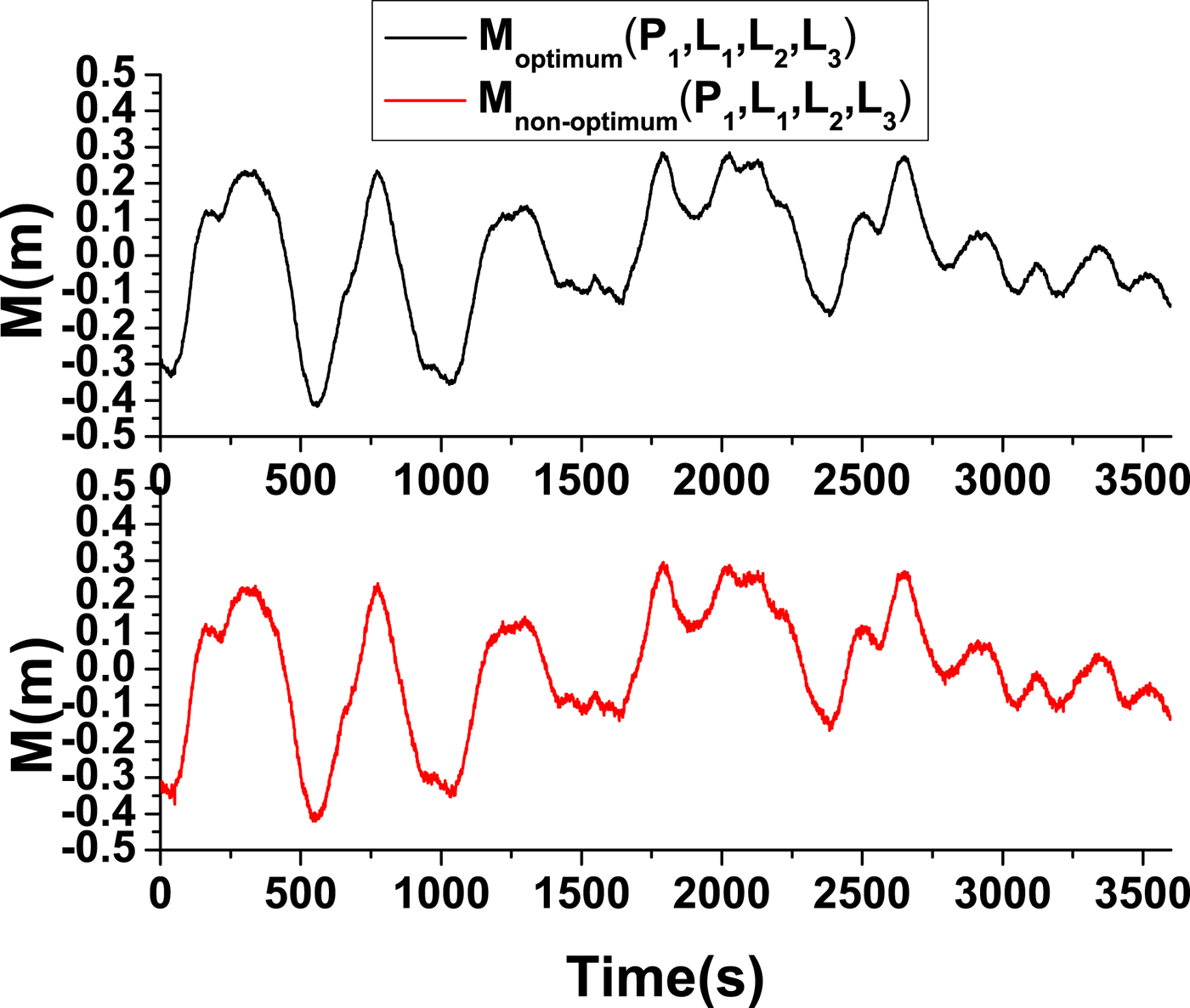
Figure 11. Multipath observation of BDS B1 under the optimum and the non-optimum combinations.

Figure 12. Multipath observation of BDS B2 under the optimum and the non-optimum combinations.

Figure 13. Multipath observation of BDS B3 under the optimum and the non-optimum combinations.
8.2. Data analysis on second order ionospheric error elimination
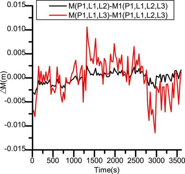
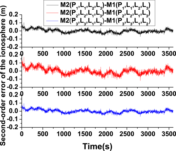
Equation (16) contains the second-order ionospheric error, while the second-order ionospheric error is eliminated in Equation (22). The second-order ionospheric error can be extracted by the subtraction between Equations (16) and (22). The one-hour city canyon data of BDS B1I, B2I and B3I are analysed in Figure 14.

Figure 14. Code phase difference on B1, B2, B3 between two triple-frequency combinations.
As shown in Figure 14, the fluctuations of the second-order ionospheric error are approximately 0·1 m. This is consistent with previous results (Wang et al., Reference Wang, Wu, Zhang and Meng2005). The results demonstrate that the proposed method can be used to eliminate the second-order ionospheric errors effectively.
9. CONCLUSION
The multi-frequency BDS code-multipath combination measurements were utilised to separate multipath and ionospheric errors. The multipath effect on code measurements has been investigated extensively, while that on carrier phase is not well investigated in the code-multipath combination. However, there are some other errors, including the hardware delay, carrier measurement noises and biases from satellites, which will influence the code multipath measurement. The different characteristics of ionospheric error on code phase and carrier phase have been investigated to propose an optimum method of multi-frequency BDS code-multipath combination measurement. We have defined the carrier amplifier factor Ω, indicating an amplified ratio of error and biases in combination equations. According to the data analysis, the optimum triple-frequency combination solution can eliminate the first order ionospheric error and has the minimum error on the carrier phase. Similarly, the quad-frequency optimum code-multipath combination can effectively eliminate the second order ionospheric error, with less impact on the measurement of code multipath effect. By utilising the optimum combination, the code multipaths of different frequencies can be detected accurately. The measurements of the Perth BDS IGS station as well as the actual sampled three and four frequency signals from a city canyon were used to validate the optimisation result. By comparative analysis, we have found that the fluctuations of the optimum triple-frequency combination are smaller than those of the non-optimum combination. It was verified that the bias and error of carrier phase were more amplified by the non-optimum combination, while the optimum combination can minimise them. The multi-frequency code-carrier combination can be also used to eliminate the second-order ionospheric error. Recently, BDS-3 has released the Interface Control Document (ICD) of B1C, B2a and B3I. The proposed optimal solution of quad-frequency BeiDou code-multipath combination may be available soon. With the development of GNSS, the number of navigation satellite signal frequencies will be increased and the optimal combination may also be widely used in the future.