1. INTRODUCTION
Precise position information is of great value in many applications, especially where the knowledge of the correct coordinates and/or movement parameters is essential to provide a high level of safety. Aviation is a good example of this. The position of an aircraft must be known by its pilots, air traffic control agencies and, in many cases, also by other users of the airspace. The lack of position information or wrong coordinates may lead to dangerous situations and accidents. Therefore, it is commonly agreed that aviation should not rely on a single radio navigation or radiolocation system. Unfortunately, in many cases this principle is not yet fulfilled, especially in the field of radiolocation: the basic tool and the main source of aircraft position data for air traffic control are radars, both Primary Surveillance Radars (PSR) and Secondary Surveillance Radars (SSR) (International Civil Aviation Organization (ICAO), 2001). In order to provide a backup solution for the radar-based positioning service, all sectors of the monitored airspace should be covered by at least two independent radar stations. However, there are still some areas covered only by one (PSR or SSR) radar. The implementation of active backup radar stations in such areas may be costly and, what is sometimes more important, may cause severe protests from local residents against high power radio emissions from radar stations. Therefore, it is understandable that other backup positioning systems for aviation, such as the Automatic Dependent Surveillance-Broadcast service (ADS-B) or Wide Area Multi-Lateration (WAM, MLAT), are gaining in importance, mostly because of their lower cost and passive operation (the majority of WAM sensors require only a receiver). Both of the above-mentioned solutions require transmission of some radio signals by on board devices, but their principle of operation differs significantly. The ADS-B system is able to provide much more data regarding the flight/traffic information or weather conditions etc., but it depends on position estimation performed by on board devices such as Global Navigation Satellite System (GNSS) receivers and/or inertial navigation. In contrast, as WAM systems are able to calculate the aircraft position by using the differences in the time of arrival of signals to a set of ground stations (sensors), and because WAM receivers usually utilise SSR transponder signals working in A, C or S mode, or even irregular pulses transmitted from Distance Measuring Equipment (DME), this solution offers backward compatibility with the simple on board equipment already installed in thousands of commercial, military and private aircraft. The ability of independent position calculation and backward compatibility with the existing equipment makes WAM a perfect complement to the existing radar-based surveillance systems and justifies the installation of WAM systems in many countries all over the world.
Unfortunately, positioning based on MLAT also has some disadvantages and limitations. The most important one is synchronisation: in a typical implementation, all ground receivers (sensors) must be synchronised in time with an accuracy of less than tens of nanoseconds. For MLAT systems covering small areas, such as the proximity of an airport or a small sector of airspace, precise synchronisation of all MLAT receivers may be achieved by using a dedicated fibre network (Tian et al., Reference Tian, Hou, Xie and Cheng2017; Sliwczynski et al., Reference Sliwczynski, Krehlik, Imlau, Ender, Schnatz, Piester and Bauch2016) or a reference transmitter (Neven et al., Reference Neven, Quilter, Weedon and Hogendoorn2005). However, in WAM systems, remote sensors are frequently installed in places distant from the central processor of the system, so it is often impossible to build a dedicated communication network able to provide a sufficient level of synchronisation. Instead, rented links via global communication networks are usually used to transmit data from the sensors, while the timestamps from GNSS (in practice mainly Global Positioning System (GPS)) receivers are used for synchronisation purposes. Many reported examples of operational WAM systems rely on GNSS-based synchronisation of measurements for aircraft position estimation (Miyazaki et al., Reference Miyazaki, Koga, Ueda, Kakubari and Nihei2011; Langhans et al., Reference Langhans, Scheiflinger, Weidner, Auer, Fitzgerald and Anzalone2013; Neufeldt and Stanzel, Reference Neufeldt and Stanzel.2013). The accuracy of satellite-based synchronisation, even using the GPS Standard Positioning Service (SPS) is not less than tens of nanoseconds, so this method of ground sensor synchronisation is adequate for most WAM implementations. Some drawbacks of GPS caused by a limited possibility of the integrity check failing have been resolved by augmentation systems such as the Wide Area Augmentation System (WAAS) and European Geostationary Navigation Overlay Service (EGNOS), which allow integrity checking and are able to provide warnings about an abnormal operation of the components of the GPS system. However, there is still some possibility of system failure or intentional GPS signal jamming and spoofing. For example, the clock failure on one GPS satellite in January 2016 (incorrect time offset information caused by a wrong configuration) (Kovach et al., Reference Kovach, Mendicki, Powers and Renfro2016; Yao et al., Reference Yao, Lombardi, Novick, Patla, Sherman and Zhang2017) caused a malfunction of many GPS-based time/frequency clocks making them unreliable for tens of hours (Chronos Technology, 2016). Even if we take into account that the probability of such failure is low, the possibility of intentional or accidental jamming of the GPS signals may be an important issue. Therefore, some other sources of backup synchronisation signals for the remote sensors, or alternatively, some WAM solutions which do not require precise sensor synchronisation, may improve the availability and reliability of the MLAT-based positioning service.
Several research groups have been working to develop asynchronous localisation systems based on time measurements. In Li and Huang (Reference Li and Huang2004), the location system consists of distributed and autonomous sensors at fixed and known positions. In that system, the object, the position of which must be estimated, emits some designed and known signals with a defined repetition time, known by the master station. The differences between the expected and the observed interval between the received signals are used to estimate the clock drift between the sensors and the position of the tracked object. In Pelant and Stejskal (Reference Pelant and Stejskal2011) the position of an aircraft is estimated on the basis of the measurements taken by receivers which are not synchronised, but this solution requires some additional information such as the data from the previously reported known position of the aircraft. The solution presented in Zhou et al. (Reference Zhou, Wang and Tian2014) is based on the rotated beam transmitted by the ground radar, therefore the MLAT system using this principle cannot be treated as a backup to radar-based positioning. A different group are asynchronous positioning systems such as those presented in Xiong et al. (Reference Xiong, Chen, An and Yang2015), Sathyan et al. (Reference Sathyan, Humphrey and Hedley2011), Wang et al. (Reference Wang, Leus and Ma2011) and Xu et al. (Reference Xu, Sun, Yu and Yang2013). As all these systems rely on two-way communication with a tracked mobile node or require an additional reference (special) node to be present in the area of operation; their application in the aviation industry may be limited.
Asynchronous positioning systems were also discussed by the authors of this paper in earlier publications. The principle of operation of the Asynchronous WAM system (AWAM), in which a group of remote non-synchronised sensors works with a master sensor synchronised with a SSR station responsible for triggering the onboard SSR transponder signals is described in Stefanski (Reference Stefanski2014). Another asynchronous solution in which the pulses (radio signals) from the on board transmitter with a constant (and known) pulse repetition period are received by a group of non-synchronised WAM sensors is described in Stefanski (Reference Stefanski2015). However, the assumptions that the pulse repetition period is known or the radar station triggering the on board transponders is present may be difficult to fulfil in practice, which limits the practical usefulness of these solutions.
This paper proposes a novel method of aircraft position estimation using non-synchronised ground sensors. In this solution, the position of one or more aircraft is estimated on the basis of a series of signals transmitted by on board transmitters where the repetition time may be unknown and even variable (irregular). It allows the use of many kinds of signals already broadcast by aircraft transmitters such as SSR, ADS-B and even DME pulses for MLAT positioning. As the proposed asynchronous MLAT solution with an irregular pulse repetition time is based on the previous work, Section 3 of this paper contains a description of the asynchronous multi-lateration system already presented in literature, while the main contribution of the fully asynchronous MLAT is presented in Section 4. Section 5 discusses the results of computer simulations taking into account the variable accuracy of the time measurements taken by the sensors. The impact of the sensors' clock instability on the accuracy of the position calculation is mentioned in Section 5.5. The article is summarised with some comments on the possibility of implementing a fully asynchronous MLAT system utilising the irregular signal repetition time from on board DME transmitters. As the majority of signals which are currently used for multi-lateration in aviation applications (SSR, ADS-B, DME) are a series of pulses transmitted in the Ultra-High Frequency (UHF) band, a term “pulse” will be hereinafter used to describe any signal transmitted from an on board device which may be used for position estimation in the MLAT system, even if the specific signal is made of more than one pulse or is based on modulation of a continuous carrier instead of pulses.
2. AWAM SYSTEM STRUCTURE
In the proposed asynchronous multi-lateration system a set of N ground stations (sensors), all of them working asynchronously, is responsible for calculating K sets of coordinates of the aircraft in a Three-Dimensional (3D) space. These coordinates may represent K independent aircraft sending their MLAT signals at random moments in time, but also K positions of one aircraft in the consecutive time moments defined by the transmission of the radio signals from an on board transmitter. The minimum number of sensors N and the number of sounding signals K required to solve the position calculations will be specified later, after the definition of equations and their transformation into the final form.
A graphical representation of the problem under consideration is presented in Figure 1. The designators of some variables regarding the signal propagation paths presented with the dashed arrows were removed to improve the clarity of this figure.
Figure 1. Geometry of the problem under consideration.
The Cartesian coordinates (x Sn, y Sn, z Sn) of the n-th ground station (sensor), where n = 1 to N, are assumed to be known, while the coordinates (x Pk, y Pk, z Pk) of the aircraft in k-th position (k = 1 to K) must be estimated on the basis of the time measurements taken by N sensors receiving K radio signals (pulses) transmitted at the unknown timestamps. Let us use Δ t n, k to denote the signal propagation time for the distance between the k-th position of the aircraft and the n-th sensor:
 $$\Delta t_{n,k} = \displaystyle{{\sqrt {{(x_{Pk} - x_{Sn})}^2 + {(y_{Pk} - y_{Sn})}^2 + {(z_{Pk} - z_{Sn})}^2} } \over v}$$
where v is the radio wave propagation speed in air. In typical synchronous MLAT systems, the time of emission of the signals from the aircraft t Pk is unknown, but every pair of synchronised sensors m and n is able to measure the Difference in the Time Of Arrival (TDOA) of the sounding signal t m, k − t n, k:
 $$t_{m,k} - t_{n,k} = \Delta t_{m,k} - \Delta t_{n,k}$$
The TDOA measurements taken by a set of four or more sensors, not located on the same plane, allow finding the coordinates of the aircraft in a 3D space. In this case, it is possible to calculate the position even when only one sounding signal is transmitted; therefore, the synchronous systems are able to track even a single aircraft in the space covered by the MLAT service.
When time synchronisation between the sensors is not available (for example, in the case of a GNSS timestamp signal failure), the sensors are no longer able to provide the TDOA measurements between different ground stations. However, if they are still able to maintain a sufficient short-term accuracy of their own time measurements, there is a possibility of estimating the position of the tracked aircraft by taking into account several aircraft transmitting MLAT signals in a short period of time, or alternatively, several consecutive positions of one aircraft. The two variants of the multi-lateration system with non-synchronised ground sensors will be presented below: one solution requiring knowledge of the time between the emission of MLAT signals from the aircraft (hereinafter called “Asynchronous 1”), and the second multi-lateration system, fully asynchronous with the irregular and unknown time between the consequent MLAT signals (“Asynchronous 2”).
3. ASYNCHRONOUS MULTILATERATION WITH REGULAR PULSE REPETITION
We assume that the time between the MLAT pulses is known by all ground sensors, which may correspond, for example, to a regular pulse repetition with a constant interval. This solution has already been published in Stefanski (Reference Stefanski2015) and will be further used as a reference point for comparison with the position estimation accuracy of a new method of asynchronous MLAT system arrangement.
For a given difference between the time of transmission of the MLAT signals from the i-th and k-th position of the aircraft: t Pi − t Pk, the following equation may be written for the n-th sensor:
 $$t_{Pi} - t_{Pk} = (t_{n,i} - \Delta t_{n,i}) - (t_{n,k} - \Delta t_{n,k})$$
Substituting Equation (1) for Equation (2) we get:
 $$\eqalign{ t_{Pi}& - t_{Pk} = \cr & = \left( {\displaystyle{{\sqrt {{(x_{Pk} - x_{Sn})}^2 + {(y_{Pk} - y_{Sn})}^2 + {(z_{Pk} - z_{Sn})}^2} } \over v} - \displaystyle{{\sqrt {{(x_{Pi} - x_{Sn})}^2 + {(y_{Pi} - y_{Sn})}^2 + {(z_{Pi} - z_{Sn})}^2} } \over v}} \right) \cr & \,\,\,- (t_{n,k} - t_{n,i})}$$
where (t n, k − t n, i) is the difference in the time of the arrival of the signal transmitted by the k-th aircraft and the i-th aircraft measured directly by the n-th ground sensor. One sensor in the asynchronous MLAT system, which received signals from the K aircraft, may provide (K − 1) independent measurements (t n, k − t n, i). On the other side, every aircraft requires estimation of three independent variables (Cartesian coordinates). Therefore, the possibility of obtaining a unique solution from a set of Equations (4) will depend on the selection of the number of sensors N and the number of aircraft K to meet inequality N(K − 1) ≥ 3K. The minimal values of K for a given N in the case when no aircraft is co-linear with any pair of the base stations nor any two aircraft are co-linear with any base station are summarised in Table 1.
Table 1. Minimum number of the aircraft tracked by variable number of asynchronous sensors in the case when the time between the signals from the aircraft is known.

A slight modification of the presented asynchronous MLAT system, in which the time between the emission of the signals from the consequent positions of one aircraft is unknown but constant, has been presented in Stefanski (Reference Stefanski2015). However, that modification makes the asynchronous MLAT system unable to track several different aircraft due to the impossibility of synchronising the MLAT transmitters in separated planes and will not be included in the performance comparison in Section 5 of this paper.
4. NEW METHOD OF SYNCHRONOUS MULTI-LATERATION WITH IRREGULAR PULSE REPETITION
In the practical implementation of the asynchronous MLAT system, the assumption that the time between the emission of the consequent MLAT signals is known may be impossible to fulfil. In the case when only one aircraft is tracked using several consequent sounding signals, the implementation of the asynchronous MLAT defined by a set of Equations (4) would require a new kind of on board transmitter with the ability to send signals with repetition time in the order of seconds and timing accuracy in the order of nanoseconds. The currently used on board radio navigation or radio location transmitters (SSR, ADS-B, DME) cannot provide the required accuracy of signal repetition time. In the other possible application, when several aircraft are tracked with single signals transmitted by all of them in a short period of time, the knowledge of the exact emission time of the signals from different on board transmitters may be even more difficult, because any external synchronisation of such transmitters, for example using a triggering signal from the secondary surveillance radar or a ground transmitter, introduces a timing error connected with a different propagation time between the source of the trigger signal and the onboard MLAT transmitters. Therefore, the time between the transmission of the MLAT signals from separate aircraft, or even consequent pulses from one aircraft, should be assumed as unknown and variable (irregular).
The unknown difference in the time of the emission of pulses (MLAT signals) from the i-th and the k-th aircraft t Pi − t Pk may be removed from Equation (3) by the subtraction of the two equations defined for two sensors, m and n:
 $$0 = [(t_{m,i} - \Delta t_{m,i}) - (t_{m,k} - \Delta t_{m,k})] - [(t_{n,i} - \Delta t_{n,i}) - (t_{n,k} - \Delta t_{n,k})]$$
Therefore, in comparison with the classic TDOA equations from the synchronous MLAT system, we make a double subtraction: the first is necessary to remove the unknown differences in synchronisation between two sensors which are included in Equation (5), while the second subtraction removes the unknown time between the emission of the MLAT signals, received by a pair of ground sensors.
 $$\eqalign{ 0 &= \left( {\displaystyle{{\sqrt {{(x_{Pk} - x_{Sm})}^2 + {(y_{Pk} - y_{Sm})}^2 + {(z_{Pk} - z_{Sm})}^2} } \over v} - \displaystyle{{\sqrt {{(x_{Pi} - x_{Sm})}^2 + {(y_{Pi} - y_{Sm})}^2 + {(z_{Pi} - z_{Sm})}^2} } \over v}} \right) \cr & - \left( {\displaystyle{{\sqrt {{(x_{Pk} - x_{Sn})}^2 + {(y_{Pk} - y_{Sn})}^2 + {(z_{Pk} - z_{Sn})}^2} } \over v} - \displaystyle{{\sqrt {{(x_{Pi} - x_{Sn})}^2 + {(y_{Pi} - y_{Sn})}^2 + {(z_{Pi} - z_{Sn})}^2} } \over v}} \right) \cr & - \left[ {(t_{m,k} - t_{m,i}) - (t_{n,k} - t_{n,i})} \right] }$$
The subtraction of time values from measurements taken at different times by different sensors without additional modelling of the time measurement errors in Equation (6) is possible by taking into account a spectral distribution of the phase noise of oscillators used for clocking the time measurements taken by the sensors. In the proposed MLAT system, the ground sensors measure the time between the received signals reaching hundreds of milliseconds up to several seconds with an accuracy of tens of nanoseconds. Therefore, the high-frequency phase noise in local clocks will have a negligible impact on the accuracy of the measurements. On the other hand, the low-frequency clock noise components, caused by the aging of the oscillators, the drift resulting from the environmental factors or a random walk frequency modulation (Riley, Reference Riley2008), introduce slow changes in the clock frequency, so time measurement errors caused by imperfect clocking will be correlated. For a short time between measurements, the upper bound of this component of measurement errors may be easily estimated using short-term oscillator stability parameters and may be limited to values much below the precision of time measurement method even for low cost crystal oscillators (Zhou et al., Reference Zhou, Nicholls, Kunz and Schwartz2008). The impact of the slow clock drift in ground sensors is described in Section 5.5.
It is obvious that in comparison with the synchronous MLAT or the asynchronous MLAT with a known pulse repetition time, the double subtraction of measurement data in Equation (6) causes some drawbacks. The most important ones are:
– Higher susceptibility to time measurement errors;
– Need for more sensors;
– Need for at least two sounding signals sent at different moments in time;
The subtraction of measurement results (t m, i − t m, k) and (t n, i − t n, k) in Equation (5) without the corresponding reduction of the total number of the unknown variables (3 ·K Cartesian coordinates of the K aircraft) means that more independent measurement results are required in comparison with the solution presented in Section 3. In Equation (5), the data received from one sensor is used to remove the unknown time between the emission of the positioning signals from the measurement results obtained from all other sensors, therefore N sensors allow us to define N − 1 independent equations. The number of nodes N and the number of the aircraft K must then meet the inequality (N − 1)(K − 1) ≥ 3K, so in comparison with asynchronous MLAT with a known pulse repetition frequency, there is a need for one more ground sensor. The relation between the number of sensors N and the number of tracked aircraft K required to obtain a unique solution from a set of Equations (6) is summarised in Table 2.
Table 2. Minimum number of aircraft tracked by a variable number of asynchronous sensors in the case when the time between signals from the aircraft is unknown.
5. SIMULATIONS OF SYNCHRONOUS AND ASYNCHRONOUS MLAT
In order to validate the possibility of calculating the 3D coordinates of the aircraft on the basis of the measurements taken by a set of ground sensors working asynchronously, a dedicated simulation software in C/C ++ was prepared, which implements the equations defined in Sections 2-4 in the form of a gradient descent algorithm. To obtain results corresponding to the actual conditions, the choice of the coordinates of the base stations (sensors) was based on real sites selected as the candidates for the MLAT system designed as a backup to the secondary radar in the Terminal Manoeuvring Area (TMA) of Gdansk airport (EPGD) in northern Poland. The WGS84 coordinates of sensors are summarised in Table 3. However, during all simulations the estimation of position of the aircraft was performed in Earth-Centred Earth-Fixed (ECEF) Cartesian coordinates.
Table 3. Coordinates of MLAT sensors in WGS84, used in computer simulations.

Although estimation of the aircraft coordinates is also possible by using the asynchronous MLAT system with irregular pulse repetition in the case when only five ground sensors are used, the authors decided to simulate a scenario with all six sensors, as presented in Table 3. This allowed us to avoid high position estimation errors caused by a bad geometry which may occur in the five-sensor scenario, when a tracked aircraft is close to one of the axes defined by any pair of sensors in a 3D space. The same set of six sensors was also used in a simulation of a fully synchronous multi-lateration system and an asynchronous one with known time between the transmission of the MLAT signals, so the results of those simulations allow us to make a simple comparison of performance of the MLAT system with and without synchronisation. During all simulations, the positions of the tracked aircraft were generated randomly with a uniform distribution of longitude in the range between 16° E and 22·1° E, the latitude between 53·1° N and 54·9° N and an altitude above the WGS84 geoid between 3,000 and 15,000 metres. Figure 2 presents a map of northern Poland with the location of the sensors and the limits of the coordinates of the simulated aircraft. Since a closed form solution of a set of nonlinear Equations (4) or (6) is unknown, the gradient descent algorithm has been used to find an approximation of the coordinates in computer simulations. Instead of closed form expressions, which are widely presented in literature (Leonardi et al., Reference Leonardi, Mathias and Galati2009), a successive approximation of the coordinates of the aircraft by the gradient descent algorithm was also used during the simulation of the synchronous MLAT to allow a direct performance comparison between the synchronous and asynchronous MLAT systems. The differences in the implementation of the gradient descent algorithms in the synchronous and asynchronous cases are outlined below. All simulations were carried out without any filtering of the estimated coordinates of the aircraft by using their history of movement. Real radio location systems always have some data filtering (for example, a Kalman filter) to reduce dispersion of coordinates introduced by measurement noise.
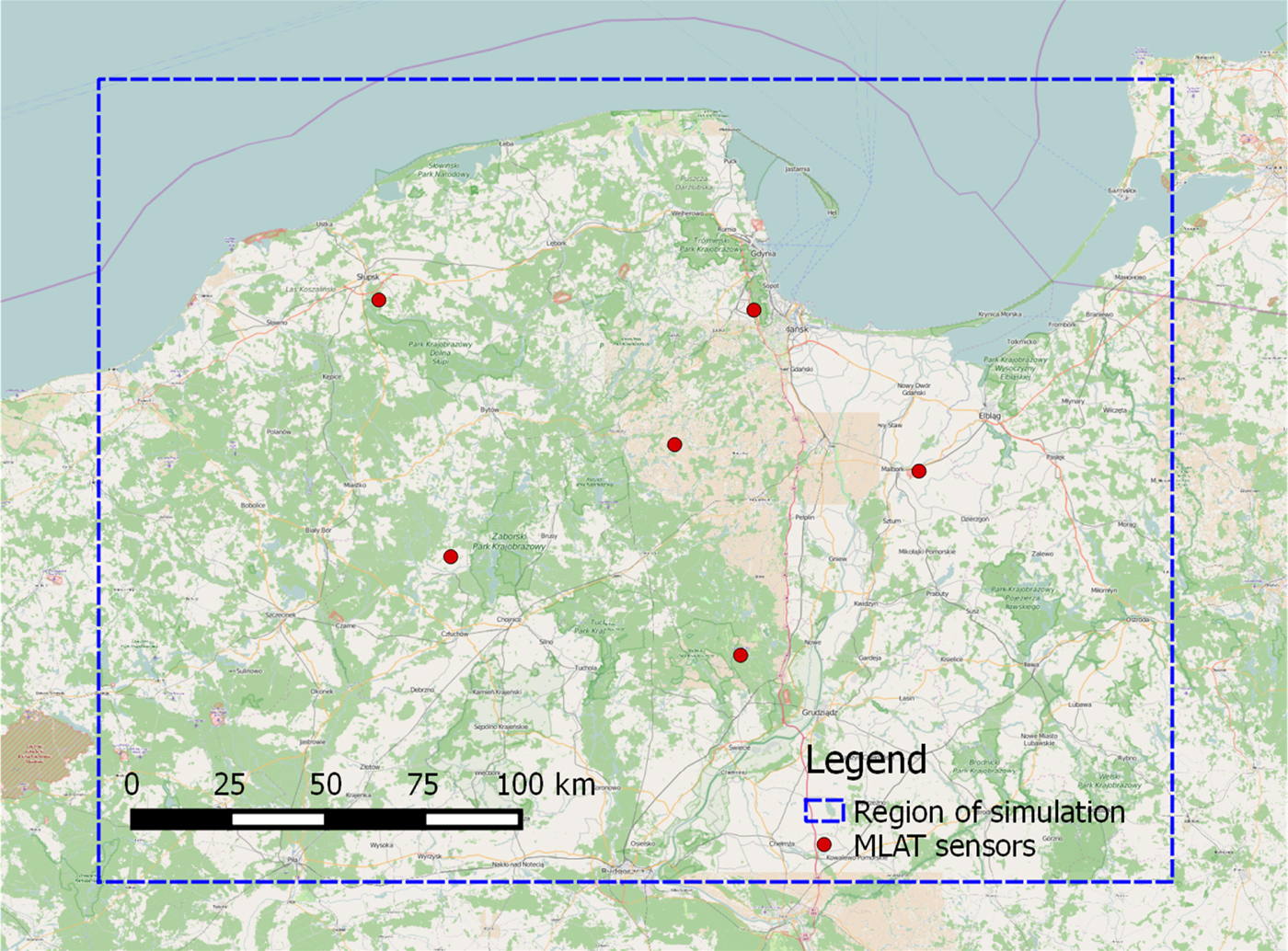
Figure 2. Position of sensors and the boundary of the area used for the simulation of asynchronous MLAT systems.
5.1. Synchronous MLAT
The classic synchronous implementation of the multi-lateration system can estimate coordinates of every aircraft separately, so the gradient descent algorithm has been applied independently to all sets of TDOA values obtained from randomly generated coordinates of 1,000 aircraft. The gradient descent algorithm was responsible for finding the minimum value of the following target function defined for only one aircraft as:
 $$F_1 = \sum\limits_{m = 1}^{N - 1} {\sum\limits_{n = m + 1}^N {{\left[ {(\Delta t_{n,1} - \Delta t_{m,1}) - (t_{n,1} - t_{m,1})} \right]}^2} }$$
where N is the number of sensors (which equals six), all time values are in microseconds and Equation (1) was substituted in Equation (7) to obtain the equations containing the Cartesian coordinates of the sensors and the tracked aircraft. The algorithm was terminated when the value of F 1 dropped below 10−8 or after 1,000,000 repetitions, whichever came first. The measurement errors were modelled as Gaussian random variables and added to all values of the time the MLAT signals occurred in all sensors: t n, 1 and t m, 1.
5.2. Asynchronous MLAT with known time between pulses
An asynchronous multi-lateration system with known time between pulses cannot be used to calculate the coordinates of one aircraft separately, therefore the target function for the gradient descent algorithm must be defined for a series of K aircraft:
 $$F_2 = \sum\limits_{n = 1}^N {\sum\limits_{i = 1}^{K - 1} {\sum\limits_{k = i + 1}^K {{\left[ {(\Delta t_{n,k} - \Delta t_{n,i}) - (t_{n,k} - t_{n,i})} \right] }^2} } }$$
Unfortunately, the gradient descent algorithm used to minimise the value of F 2 converges very slowly, especially when some of the aircraft are located in close proximity to each other (hundreds of metres). The convergence speed may be significantly improved by taking into account that when the coordinates of K aircraft are already found in the previous iteration of the simulation, a rough approximation of the coordinates of the new aircraft number K + 1 may be obtained using the limited gradient descent algorithm with the coordinates of all other K − 1 aircraft from the previous step initially assumed to be constant. It gives a quick convergence of the coordinates of the aircraft number K + 1 near the final solution. After that the coordinates of all the K aircraft in the last step are again treated as variables and corrections of all coordinates of the aircraft are made using the full implementation of the gradient algorithm. The first part of the gradient descent algorithm with constant coordinates of the other aircraft was terminated after 100,000 repetitions or when F 2 dropped below 10−6, then the second part with all the coordinates as variables was repeated until F 2 dropped below 10−8 or after 300,000 repetitions, whichever came first.
The time between the transmission of the signals from the on board transmitters was modelled as a random variable with a uniform distribution in the range between 10 ms and 1 s. Other parameters of the simulation were the same as in the case of the synchronous MLAT described in Section 5.1.
It should be noted that the gradient descent algorithm used to find the approximate solution of the nonlinear set of Equations (4) may converge to some local minima instead of the global one, when the initial values of coordinates are improperly selected. In practical application, the results from the genetic algorithm may be used as the initial coordinates for the gradient descent algorithm or may include some mechanisms restarting in the case of an incorrect convergence to a solution far away from the selected threshold of F 2.
5.3. Asynchronous MLAT with irregular pulse repetition time
In the case when the asynchronous MLAT system must be able to estimate the coordinates of the aircraft sending their signals at unknown timestamps, the target function for the gradient descent algorithm may be:
 $$F_3 = \sum\limits_{m = 1}^{N - 1} \sum\limits_{n = m + 1}^N \sum\limits_{i = 1}^{K - 1} \sum\limits_{k = i + 1}^K \left[((\Delta t_{m,k} - \Delta t_{m,i}) - (\Delta t_{n,k} - \Delta t_{n,i})) - ((t_{m,k} - t_{m,i}) - (t_{n,k} - t_{n,i})) \right]^2$$
Other parameters of the simulation, as well as all comments regarding the method of increasing the convergence speed mentioned in Section 5.2 are also valid for the simulation of an asynchronous MLAT with irregular pulse repetition.
5.4. Results of simulations
Figures 3–5 present a comparison between the cumulative distribution of the absolute position error estimated on the basis of the simulations of the synchronous and two variants of the asynchronous multi-lateration system: with the known pulse repetition time (“Asynchronous 1”) and with the assumption that the pulses are sent in an irregular and unknown way (“Asynchronous 2”). Due to the fact that the performance of the asynchronous MLAT in the presence of the time measurement errors depends on the number of measurements used to calculate the coordinates of the aircraft, but as the number of the sensors used for the simulation is assumed to be constant (six ground stations), the results of the simulation for the asynchronous MLAT will depend on the number of aircraft tracked at the same time. Therefore, the error distribution charts contain the results obtained for a different number of aircraft: three, five and seven for the asynchronous implementation, while the synchronous MLAT was simulated with the equations defined for only one aircraft at the same time (independent position estimation for all sets of measurement data). Figures 3–5 show that the position estimation error in the asynchronous MLAT with unknown time between the signals transmitted from five aircraft (“Asynchronous 2”) is typically twice as big as the position estimation error in the fully synchronous MLAT with the same set of ground sensors. This relation is approximately constant for different values of time measurement errors modelled by the Gaussian random value.

Figure 3. Cumulative distribution of the absolute position error for synchronous and asynchronous MLAT with time measurement errors modelled by a normal distribution with a standard deviation 3ns.

Figure 4. Cumulative distribution of absolute position error for synchronous and asynchronous MLAT with time measurement errors modelled by a normal distribution with a standard deviation 10 ns.
Figure 5. Cumulative distribution of absolute position error for synchronous and asynchronous MLAT with time measurement errors modelled by a normal distribution with a standard deviation 30ns.
The asynchronous MLAT system with known time between the emission of the radio signals (“Asynchronous 1”) and with a relatively large number of the tracked aircraft (seven) tends to give slightly more results with a very low absolute position estimation error than the synchronous one. This is mainly caused by the fact that in the asynchronous MLAT, the time measurement noise from all measurements influences at the same time (but not in the same way) the estimates of all coordinates of the K tracked aircraft, giving an effect similar to the weighted averaging of noise from all measurements. It should not be concluded that the asynchronous MLAT performed better than the synchronous solution, as there were differences in the number of measurements used to calculate the position and therefore creating unequal conditions for a performance comparison.
The standard deviation of the time measurement error which equals 3 ns (Figure 3) corresponds to a distance error of one metre. Unfortunately, in the 3D positioning systems with all sensors placed almost at the same height, which is common in wide area multi-lateration, high values of Dilution Of Precision (DOP), especially for the z coordinate, significantly reduce the accuracy of position estimation. Therefore, in 50% of all simulated datasets, the accuracy of position estimation was not higher than 10 m for both the asynchronous MLAT with known pulse repetition frequency and a high number of tracked aircraft (seven) and the synchronous MLAT. The accuracy of the position estimation in the proposed MLAT system without knowledge of the pulse repetition frequency is typically twice as bad in comparison to the mode with known pulse repetition frequency, which can be fully explained by taking into account that in the latter case the noisier measurements are present in every positioning equation.
If we consider the dimensions of a real aircraft and the accuracy of flight guidance that can be obtained during the flight, in most cases precision of the position estimation using the proposed asynchronous MLAT with irregular pulse repetition frequency seems to be satisfactory even for a standard deviation of time measurement error that equals 10 ns (Figure 4). The results obtained for 30 ns time measurement error (Figure 5) are below expectations, which is also confirmed by the high values of the Mean Error (ME), as well as the position estimation errors not exceeding in 50% and 95% of all cases summarised in Table 4.
Table 4. Position estimation errors for synchronous and asynchronous MLAT systems.
The results of the simulation without time measurement errors will not be presented due to the fact that the only difference between the error cumulative distribution functions for such a scenario comes from the definition of the stop condition for the gradient descent algorithm, not from the differences in error characteristics of the simulated algorithms.
The asynchronous multi-lateration system which can estimate the coordinates of the aircraft even without any knowledge of the time between the emission of signals from different aircraft or any knowledge of the repetition time of several consecutive signals from one aircraft, may be implemented as a backup solution in almost all existing synchronous MLAT systems to provide continuous operation even in the case of sensor synchronisation failure. Although in general, the absolute position estimation error obtained from asynchronous MLAT will be higher when compared to synchronous systems, even such limited positioning accuracy, presented in Table 4, may be sufficient for air traffic control in the absence of other localisation services (SSR, ADS-B, synchronous MLAT).
The possibility of estimating the coordinates of the aircraft by an asynchronous MLAT system without knowledge of the time when the signals were emitted from the aircraft allows the utilisation of various signals already transmitted by on board equipment. The pulses from the on board DME (Distance Measuring Equipment) transmitters may also be used for location purposes in addition to the widely used SSR transponder signals and broadcast transmission from ADS-B. The DME pulses are sent in a pseudo-random sequence known only by the transmitter, and as such, cannot provide any kind of aircraft identification (no information encoded in the transmitted signals), but due to the relatively high average repetition frequency (24 up to 150 signals per second) it is possible to group a series of signals corresponding to a specific aircraft and then use the proposed asynchronous MLAT solution to estimate the coordinates of all aircraft sending their DME signals in a supervised area, even when the ground sensors cannot receive DME responses from a ground transponder as is assumed in typical DME-based MLAT implementations (Wu and Lefebvre, Reference Wu and Lefebvre2011; Owen, Reference Owen2007).
5.5. Impact of sensor clock drift
Due to the fact that the values of the arrival time of the MLAT signals measured by all ground sensors are included directly in Equations (4) and (6), the impact of the time measurement error caused by imperfect clocking of the sensors will be exactly the same as the impact of the measurement errors caused by a limited signal to the noise ratio and the measurement method on the accuracy of position estimation. This means that when we want to define requirements for the receiver's short-term clock stability, which is usually understood as the RMS of the relative clock drift and noise, we must take into account the time between the emission of the MLAT signals from the tracked aircraft. In the case of perfect timing of the MLAT sensors, the subtraction of the results of the measurements taken by a given sensor in Equation (4) or pairs of the sensors in Equation (6) makes the absolute value of the time between the emission of the consequent MLAT signals (either from different or the same aircraft) negligible in calculations. However, for a given value of the relative receiver clock stability η and the average time between transmission of the signals used for the MLAT position estimation τ, the absolute errors in time measurement taken by the ground sensors may be estimated as:
 $$\varepsilon \approx \; \pm \;\tau \cdot \eta$$
This simple error model is based on the assumption that the low-frequency components of noise in the clocks of the ground sensors have the greatest impact on the accuracy of the time measurements, which is valid for typical crystal oscillators. Therefore, slow changes in a clock frequency may be bounded by a linear function of the observation time.
The absolute time measurement error caused by the clocking of the receiver must be lower than the error caused by other receiver-independent factors, like a low signal to noise ratio. Assuming that the position accuracy requirements could be met when the time measurement error is of the order of 10 nanoseconds (Figure 4), the absolute error caused by the clocking should be limited to a few nanoseconds. This gives a different value of the relative clock stability depending on the source of signals for asynchronous multi-lateration:
– for SSR onboard transponders triggered by a radar interrogator with a 4 second rotation time: η ≈ 2 · 5 × 10−10;
– for ADS-B packets broadcast every 0·5 second: η ≈ 2 × 10⁻⁹;
– for DME pulses with the average repetition frequency 25 pulse pairs per second: η ≈ 2 · 5 × 10−8.
Such values of the short-term stability can be met by using crystal oscillators with temperature control (OCXO) for a DME-based application or, for example, by rubidium frequency sources for more demanding systems based on the signals with longer repetition periods.
6. CONCLUSIONS
The asynchronous multi-lateration system which allows estimation of the coordinates of an aircraft even without any knowledge of either the time between the emission of the signals from different aircraft or the repetition of the consecutive signals from one aircraft, may be implemented as a backup solution in almost all existing synchronous MLAT systems to provide continuous operation even when sensor synchronisation fails. A lack of sensor synchronisation clearly causes a reduction in the accuracy of position estimation. The asynchronous MLAT performance degradation ratio may be estimated on the basis of the results of the simulations presented in Section 5.4 of this paper.
The concept of a multi-lateration system without sensor synchronisation is based on the assumption that the sensors' clocks maintain a high short-term stability. In order to check the validity of this assumption, the parameters of real crystal oscillators should be investigated both in a laboratory and in real conditions, taking into account the impact of the clocks' drift on the performance of asynchronous MLAT. Further work may also include the Cramér-Rao Lower Bound (CRLB) analysis of both the proposed solution and the closed form equations to estimate the dilution of precision parameter for asynchronous MLAT.