1. INTRODUCTION
Methods of classic astronomical navigation are slowly but steadily becoming obsolete. Even today it is very hard to find an officer on board a ship who is familiar with the practical use of the sextant and nautical almanac. The International Convention on Standards of Training, Certification and Watchkeeping for Seafarers (STCW) (STCW, 2011) still requires all officers in charge of a navigation watch to be able to determine the altitude of a celestial body, a Line Of Position (LOP) and, eventually, the final position, but the Convention also states that the use of appropriate celestial navigation calculation software and an electronic almanac is allowed. This legal requirement is the only reason why the sextant can still be found on board many ships, but it is not expected that this requirement will last forever. Once the Global Positioning System (GPS) has other, more practical back-up positioning systems, the sextant and the classical methods of fixing position in astronomical navigation will probably become outdated. However, let us assume that certain practical solutions, or skills, will remain in the future, for example the use of Polaris for orientation, use of celestial bodies for determination of compass deviation, use of sunset/sunrise situations, meridian passage, etc. This represents the traditional knowledge and standard skills that an experienced deck officer needs to know, including the use of the sextant for determining the LOP. Another practical solution could involve the determination of LOP by knowing only the azimuth of a celestial body. This method can be useful in cases of emergency, as a replacement for classic methods in astronomical navigation. Today, the most common method is the intercept method, also known as Marcq St. Hilaire method, described in detail by Coolen (Reference Coolen1987) and Bowditch (Reference Bowditch2002). Other methods include the Dozier (direct) method and old methods such as the Sumner line of position, longitude methods and the ex-meridian method (Čumbelić, Reference Čumbelić1990; Lipovac, Reference Lipovac1981).
Several problems need to be solved prior to obtaining an LOP with only an azimuth of a celestial body. One of the major problems is how to obtain a precise compass bearing. The compass is not as precise as the sextant. The compass usually measures arcs in degrees, while the sextant performs measurement in degrees, minutes, and seconds. An azimuth error of 1°, over a distance of 60 Nautical Miles (NM) results in an error of around +/−1 NM (over 1000 NM the error is around +/−17 NM)Footnote 1 . As the modern technologies continuously provide new solutions to various practical problems, it can be assumed that it will be possible to obtain azimuths with errors of +/−0.1° or even less in the coming years.
The azimuth of a celestial body is a part of a great circle. On a Mercator navigation chart this azimuth is not a straight line, but a curve. Basically, on the Earth, it is an orthodrome (part of a great circle) from the position of the observer to the point of the Geographical Position (GP)Footnote 2 that is defined by declination and Greenwich hour angle. It is not enough to know only the great circle azimuth of a celestial body at the observer position to obtain the LOP directly. But with the Great Circle (GC) azimuth it is possible to define a curve of equal GC azimuths (further in the text: isoazimuthal curve-Figure 1). This means that the azimuth of a celestial body is the same at any point on this curve.
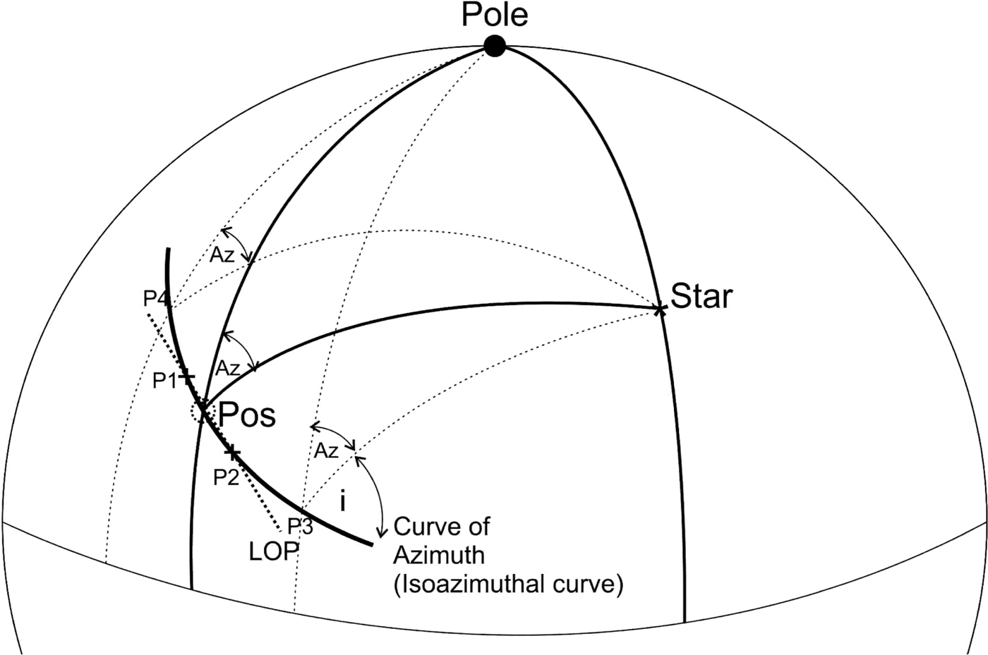
Figure 1. Curve of equal GC azimuths-isoazimuthal curve.
The LOP (straight line on the Mercator chart) can be determined by knowing two positions on the isoazimuthal curve (P1 and P2 in Figure 1), lying relatively close to each other and close to the dead reckoning position. For small distances, the line passing through the selected positions does not deviate much from the corresponding arc of the isoazimuthal curve and, accordingly, this line (azimuth line of position) can be plotted instead of the isoazimuthal curve (Flexner, Reference Flexner1943). Determination of the referent positions (P1 and P2) that define the LOP will be based on the selection of two latitudes close to the Dead Reckoning (DR) position and the calculation of their longitudes, or vice versa (selection of longitudes and calculation of latitudes).
2. THEORY
The basic navigation triangle in astronomical navigation is formed by the three arcs of three great circles: the arc of a local celestial meridian, the arc of an hour circle and the arc of a vertical circle. The main angles of this triangle include the azimuth, the local hour angle, and the angle at the celestial body, the so-called parallactic angle. Also, the main points are the zenith, the celestial pole and the star. For projecting this triangle on the Earth, the points include the position of the observer (Pos), pole on the Earth (Pn) and Geographical position GP (Figure 2).

Figure 2. Navigation triangle and its projection on Earth.
The vertical circle is the great circle passing through the zenith and the star. This great circle has a vertex. This vertex, together with the position of the observer, the Pole and the Star, makes two right-angled triangles (Figure 2). For these triangles it is possible to apply Napier's rules (Figure 3).
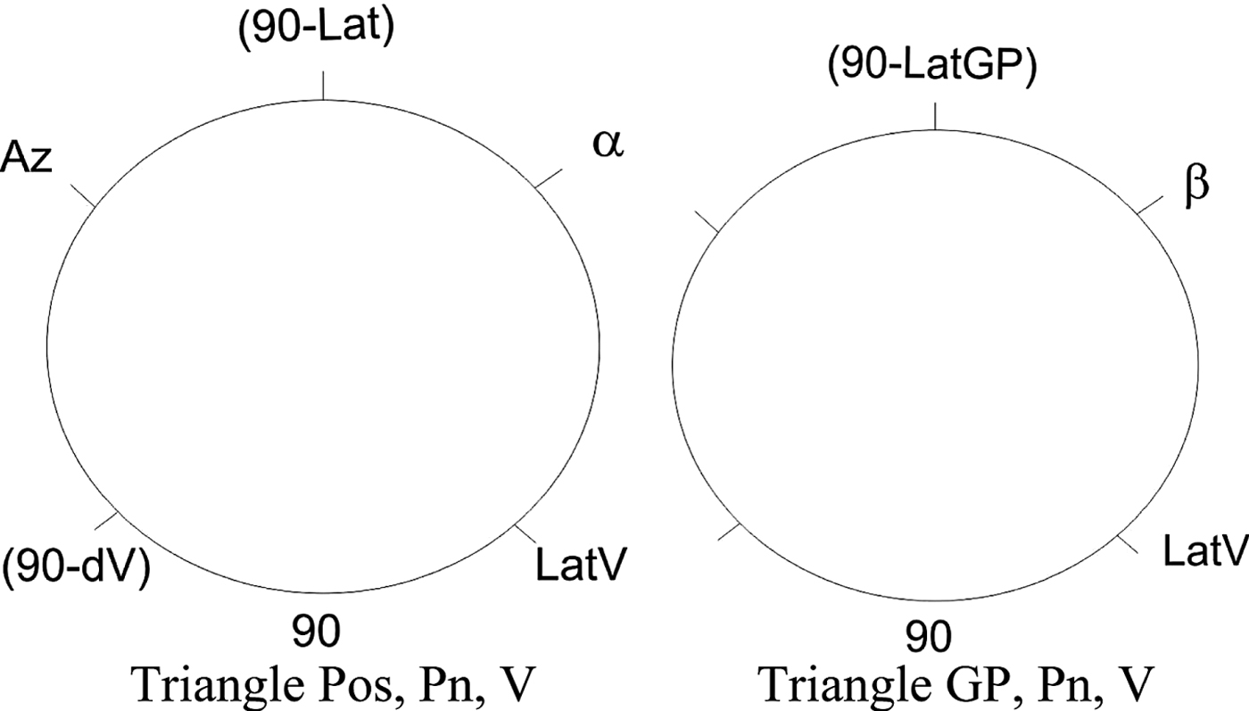
Figure 3. Napier's Rule.
The problem is to obtain the Longitude of a position on the isoazimuthal curve for the selected Latitude, or vice versa, when the known elements include the azimuth of a celestial body (Az), declination (LatGP) and Greenwich hour angle (LongGP).
2.1. Calculation of the longitude (Long) for the selected latitude (Lat)
According to Napier's Rules (Figure 3):
 $$ \hbox{Cos}(LatV)=\hbox{Sin}Az \cdot \hbox{Sin}(90-Lat) $$
 $$ \hbox{Cos}(LatV)=\hbox{Sin}Az\cdot \hbox{Cos}Lat $$
 $$ \hbox{Cos}(90-Lat)=\hbox{Cot}Az\cdot \hbox{Cot}\alpha $$
 $$ \hbox{Cot}\alpha =\hbox{Sin}Lat\cdot \hbox{Tan}Az $$
 $$ \hbox{Cos}\beta =\hbox{Cot}(90-LatGP)\cdot \hbox{Cot}LatV $$
 $$ \hbox{Cos} \beta =\displaystyle{{\hbox{Tan}LatGP}\over{\hbox{Tan}LatV}} $$
From the oblique navigation triangle Pos,V, Pn (Figure 2):
 $$DL=\alpha -\beta$$
Longitude of the observer for the selected Latitude:
 $$Long.=LongGP\hbox{-}DL$$
2.2. Calculation of the latitude (Lat) for the selected longitude (Long)
From the oblique navigation triangle Pos, V, Pn (Figure 2):
 $$DL=LongGP\hbox{-}Long$$
From the oblique navigation triangle Pos, GP, Pn, according to the sine rule:
 $$ \hbox{Sin}Az:\hbox{Sin}DL =\hbox{Sin}(90-LatGP):\hbox{Sin}dGP $$
 $$ \hbox{Sin}dGP=\displaystyle{{\hbox{Sin}DL\cdot \hbox{Cos}LatGP}\over{\hbox{Sin}Az}} $$
and according to Napier's analogue for
 $\hbox{Tan} \left( {\displaystyle{{a + b} \over 2}} \right) $
:
$\hbox{Tan} \left( {\displaystyle{{a + b} \over 2}} \right) $
:
 $$\hbox{Tan}\left({\displaystyle{{(90-LatGP)+dGP}\over{2}}} \right)=\displaystyle{{\hbox{Cos}\left( {\displaystyle{{Az-DL}\over{2}}} \right)}\over{\hbox{Cos}\left( {\displaystyle{{Az+DL}\over{2}}} \right) }}\cdot\hbox{Tan}\left( {\displaystyle{{90-Lat}\over{2}}}\right)$$
If
 $\hbox{Tan} \left( {\displaystyle{{90-Lat}\over{2}}} \right) $
is replaced by X
$\hbox{Tan} \left( {\displaystyle{{90-Lat}\over{2}}} \right) $
is replaced by X
 $$X=\displaystyle{{\hbox{Tan}\left( {\displaystyle{{(90-LatGP)+dGP}\over{2}}} \right) \cdot \hbox{Cos} \left( {\displaystyle{{Az+DL}\over{2}}} \right) }\over{\hbox{Cos} \left( {\displaystyle{{Az-DL}\over{2}}} \right) }}$$
Latitude of the observer for the selected longitude:
 $$ \left( {\displaystyle{{90-Lat}\over{2}}} \right)=\hbox{ATAN}(X) $$
 $$ Lat=90-2\cdot \hbox{ATAN}(X) $$
For practical use of the above equations, the azimuth angle Az should always be less than 180°. Thus, when the azimuth of the celestial body is greater than 180° (third and fourth quadrant) the azimuth angle should be reduced by 180°. Also, in Equation (7) the angle DL is
 $\alpha -\beta $
when the body is in the first and third quadrant otherwise it is
$\alpha -\beta $
when the body is in the first and third quadrant otherwise it is
 $\alpha +\beta$
. When the vertex is between the observer (Pos) and the star (GP), the signs are opposite (i.e.
$\alpha +\beta$
. When the vertex is between the observer (Pos) and the star (GP), the signs are opposite (i.e.
 $ {DL}= \alpha +\beta $
when the body is in the first and third quadrant and
$ {DL}= \alpha +\beta $
when the body is in the first and third quadrant and
 $\alpha -\beta $
when the body is in the second and fourth quadrant). The longitude of the vertex is determined by the angle α or β (for example longitude of vertex = longitude of observer + α, see Figure 2).
$\alpha -\beta $
when the body is in the second and fourth quadrant). The longitude of the vertex is determined by the angle α or β (for example longitude of vertex = longitude of observer + α, see Figure 2).
In addition, it is possible to define the angle between the meridian at the selected position and the isoazimuthal curve. This angle is equal the sum of Azimuth (Az) and the angle “i” (Figure 1 - angle between the star and the isoazimuthal curve). The angle “i” can be determined from the spherical triangle Star (GP), Pole, and one selected position (Figure 1) (Flexner, Reference Flexner1943):
 $$ \hbox{Tan}i=\hbox{Tan}DL\cdot \hbox{Sin}Lat$$
With the angle (Az + i) at the selected position the LOP can also be determined. In this case, only one selected position is required. The problem is that the selected position should be very close to the real position; otherwise deviation of the straight line (LOP) from the isoazimuthal curve will be significant.
3. RESULTS FOR DIFFERENT SCENARIOS
Example 1. Date: 01 September 2015; UT 23:15:00; Lat = 30°00·0’N, Long = 060°00·0’W.
The calculated azimuths and altitudes are shown in Table 1. These calculations are part of the intercept method, also known as the Marcq St. Hilaire method, currently the most common method for determination of LOP in astronomical navigation.
Table 1. SkyMateFootnote 3 Results.

The following examples (Tables 2 to 5 and Figures 4 to 7) illustrate how to obtain the position by knowing only the azimuths of the celestial bodies. It is assumed that the observer on a ship can measure these azimuths within an accuracy of +/−0·1°. Different DR (assumed) positions will be taken into account, as well as azimuths (rounded), in order to determine their impact on the line of position.
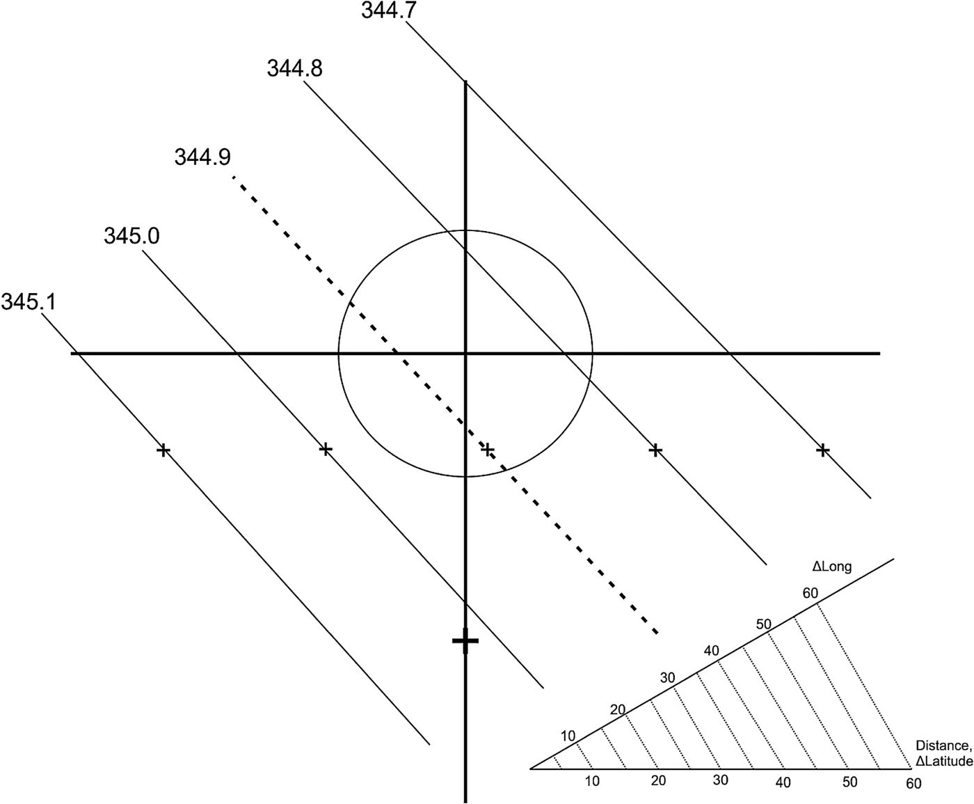
Figure 4. Lines of position (Table 2) (true position in the middle of the selected positions, the centre of the figure: 30°N/60°W).
Figure 5. Lines of position (Table 3) (true position between the selected positions but not in the middle, the centre of the figure: 30°N/60°W).

Figure 6. Lines of position (Table 4) (true position outside the selected positions, the centre of the figure: 30°N/60°W).
Figure 7. Lines of position (Table 5) (for rounded azimuths to the nearest half of a degree and true position outside the selected positions, the centre of the figure: 30°N/60°W).
Table 2. LOP calculations-true positionFootnote 4 in the middle of the selected positions.
* Selected Long. same for all bodies, only Lat. is calculated (bold text).; each LOP is defined by two selected Long. and two calculated Lat. (P1 and P2).
Table 3. LOP calculations-true position between the selected positions but not in the middle of these positions.
Bold text-calculated coordinates.
Table 4. LOP calculations-true position outside the selected positions.
Bold text-calculated coordinates.
Table 5. LOP calculations-for rounded azimuths to the nearest half of a degree and true position outside the selected positions.
Bold text-calculated coordinates.
Results from Table 2 are graphically shown in Figure 4. In Figure 4 each LOP is defined by one referent position (P1 from Table 2) and the corresponding rhumb line (between P1 and P2). The centre represents the DR position, or in this case the true (real) position of the observer (Lat. = 30°00·0’N, Long = 060°00·0’W). The auxiliary diagram is for reading distance and dLong (i.e.
 $\lambda _{2}-\lambda _{1}\rpar $
.
$\lambda _{2}-\lambda _{1}\rpar $
.
Results in Figure 4 are for an almost ideal situation: the DR (true) longitude is in the middle of the selected longitudes and azimuths have no observational error (rounded to one decimal place). The error of position for five best LOPs is within 5 NM.
In the next examples (Figures 5 and 6), the DR (assumed) position will be changed and the azimuths will remain the same.
In the last example (Figure 7) the azimuths will be rounded to the nearest half a degree, true position remains outside the selected positions.
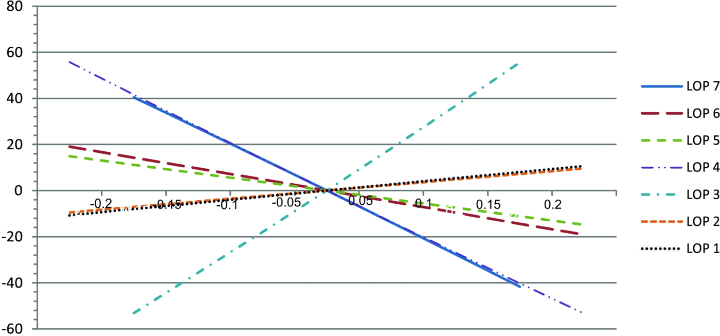
4. LOP ERROR
The results confirm that the precision of the azimuth has the largest impact on the accuracy of the Line Of Position (LOP). Let us take for example the LOP 7 (Kochab), which has the biggest errors (Figure 7). The influence of the change in azimuth on the error of LOP 7 is shown in Figure 8. In this example, every change in azimuth by a 0·1° causes a shift of LOP of around 20 NM.

Figure 8. Impact of the azimuth error on the LOP error (LOP 7-example 1) (the centre of the figure: 30°N/60°W).
For comparison, the intercept method errors, arising from all causes, in an astronomical position line, in good conditions, are expected to range between 2 to 3 NM, depending on the skills and experience of the observer (Malkin, Reference Malkin2014). Top navigators can reach a precision within 0·4 NM from the GPS position, under calm sea conditions (Hohenkerk et al., Reference Hohenkerk, Kemp and Nibbs2012).
Selected positions (P1, P2 in examples) also affect the accuracy of the LOP, but this impact is minimal. It is worth noting that, whenever possible, one should select P1 and P2 to be either side of the DR (or assumed) position. Also, results of this research suggest that it is better to choose to calculate the latitude for the selected longitude, whenever the celestial body is close to the prime vertical. When the body is near the meridian, it is a better solution to calculate the longitude for the selected Latitude. In addition, one should strive to choose celestial bodies with the GP closer to the DR position.
Figure 9 shows the latitude errors in the function of the azimuths. These latitude errors are differences between the true latitude (30°N) and the calculated latitudes for the true longitude (60°W, from example 1). In general, relatively small errors occur only within +/−0·1° of the true azimuth.

Figure 9. Latitude error (n.m.) for the true longitude (60°W) and different azimuth errors (in degrees-left/right from the true azimuth).
So, when using only azimuths, the key element in calculating the LOP is the precision of the azimuth itself. The modern ship compass and the associated sighting devices cannot give the required precision, but this does not mean that it is impossible to reach precision in general. For example, a typical (gyro) ship compass has a static error heading accuracy of +/−0·1°, while under dynamic conditions (slight to moderate rolling and pitching) the error amounts to +/−0·4°, according to a manufacturer (Raytheon, 2012). In the real situation at sea, an error under dynamic conditions is likely to be higher, at least +/ − 1° (Xu et al., Reference Xu, Liu, Shan, Zhang and Wang2014). In addition, there are also more accurate Ring Laser Gyro compasses, whether stand-alone or integrated within navigation systems, mainly used on special types of vessels, for DP systems (MGC, 2014). With slight modifications and special sighting devices, these compasses could significantly improve the precision of azimuth measurement.
5. USE OF ECDIS
Modern navigation systems, like Electronic Chart Display and Information Systems (ECDIS), can also help in astronomical navigation. Although most present-day ECDIS systems do not feature the ephemerides and the possibility of direct determination of the position using celestial bodies, options like line and circle drawing enable graphical determination of LOPs and, the position using the classic intercept method. Furthermore, even standard ECDIS can provide an approximate determination of the position by using only gc azimuths of celestial bodies, without construction of a LOP.
The procedure (Figure 10) is carried out in the following way: plot the GP as per known Greenwich hour angle and declination. Plot the GC bearing (or course) between the GP and the DR position (or assumed). Repeat the procedure for other bodies and compare the GC bearings (courses). By moving the DR position (assumed) around the first one, find the position in which GC bearings (courses) are equal to the observed azimuths. Figure 10 describes the situation given in Example 1 for the selected DR (true) position (general view), and four assumed positions on the angular distance of 30’ N/S (E/W) from the DR (true) position (for first, second and third Azimuth). An option of automatic movements of the bearings (courses) together with movements of the DR position (assumed) is not available, but future ECDIS upgrades may have this feature.
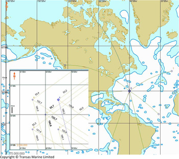
Figure 10. Using ECDIS (Transas, 2010) to plot GP and Azimuths-Example 1.
There are also methods for reducing the great circle bearing to the rhumb line (Mercator) bearing, for the selected DR (true) position. These are described in nautical publications as a correction of the great circle bearing (radio great circle bearing) (Nautičke Tablice, Reference Tablice1984; Norie's Nautical Tables, 1991). These methods are based on an observed azimuth and the known (true) position. Therefore, these methods are not appropriate for establishing an LOP in astronomical navigation.
6. CONCLUSIONS
Astronomical navigation at sea is a practice in decline, but this is not the reason to stop searching for new practical solutions in order to preserve astronomical navigation as a reliable and independent positioning system for the future. At first sight, the methods for obtaining a LOP, knowing only the azimuth of a celestial body, look very promising because they eliminate the need for a relatively complicated procedure of altitude measurement and taking into account related corrections. On the other hand, there are some disadvantages: modern ship devices cannot measure azimuths with acceptable precision, the accuracy of the position depends on the DR position error, LOP calculation is relatively complicated, the method itself is approximate, etc. The major problem is the precision of the measured azimuth, which should be within +/−0·1°, which is presently only attainable in static conditions. From a current viewpoint, this method cannot replace the Marcq St. Hilaire (intercept) method or similar methods that have been confirmed in practice. However, it can serve as an alternative to these methods and can be proved useful, especially in case of emergency. Finally, taking into account possible future development of azimuth measuring devices, greater use of software and modern navigation systems, and possible disappearance of the sextant from ships, the introduced method may gradually gain greater significance in astronomical navigation.