


1 Introduction
Square-sectioned structures are common in many engineering applications such as bridges, offshore platforms, high-rise buildings, and so on. The study of flow-induced vibrations (FIV) of these structures has great importance, especially in assessing the stability of the structures. Alternating vortex shedding and associated fluid–structure interactions generate periodic fluctuating forces on the surfaces of structures, resulting in self-excited vibrations. Vortex-induced vibration (VIV) and galloping are the most common self-excited vibration phenomena. Vortex-induced vibration occurs when the shedding frequency locks in to the structural natural frequency, while galloping vibration, in general, takes place with the shedding frequency higher or lower (Nakamura & Matsukawa Reference Nakamura and Matsukawa1987; Nakamura & Hirata Reference Nakamura and Hirata1991) than the structural natural frequency. Flow-induced vibrations have attracted widespread attention in the past decades, involving many independent parameters, e.g. mass ratio
 $m^{\ast }$
, damping ratio
$m^{\ast }$
, damping ratio
 $\unicode[STIX]{x1D701}$
, natural frequency
$\unicode[STIX]{x1D701}$
, natural frequency
 $f_{n}$
, Reynolds number
$f_{n}$
, Reynolds number
 $Re$
, reduced velocity
$Re$
, reduced velocity
 $U_{r}$
, structure shape, turbulent intensity, etc. In most previous studies on flow-induced vibrations of cylinders,
$U_{r}$
, structure shape, turbulent intensity, etc. In most previous studies on flow-induced vibrations of cylinders,
 $U_{r}$
is treated as an independent parameter (Singh & Mittal Reference Singh and Mittal2005; Zhao, Cheng & Zhou Reference Zhao, Cheng and Zhou2013), while in some other studies,
$U_{r}$
is treated as an independent parameter (Singh & Mittal Reference Singh and Mittal2005; Zhao, Cheng & Zhou Reference Zhao, Cheng and Zhou2013), while in some other studies,
 $U_{r}$
is regarded as a function of
$U_{r}$
is regarded as a function of
 $Re$
(Singh & Biswas Reference Singh and Biswas2013; Sen & Mittal Reference Sen and Mittal2015). The Reynolds number involves the flow velocity, fluid properties and structure dimension. On the other hand,
$Re$
(Singh & Biswas Reference Singh and Biswas2013; Sen & Mittal Reference Sen and Mittal2015). The Reynolds number involves the flow velocity, fluid properties and structure dimension. On the other hand,
 $U_{r}$
integrates the flow velocity, structure dimension and structure elasticity. The Reynolds number and
$U_{r}$
integrates the flow velocity, structure dimension and structure elasticity. The Reynolds number and
 $U_{r}$
are, therefore, functions of each other. As such, given the same
$U_{r}$
are, therefore, functions of each other. As such, given the same
 $U_{r}$
ranges, the vibration response characteristics may be different in different
$U_{r}$
ranges, the vibration response characteristics may be different in different
 $Re$
ranges (e.g. Barrero-Gil, Sanz-Andres & Roura Reference Barrero-Gil, Sanz-Andres and Roura2009; Kumar, Sing & Sen Reference Kumar, Sing and Sen2018).
$Re$
ranges (e.g. Barrero-Gil, Sanz-Andres & Roura Reference Barrero-Gil, Sanz-Andres and Roura2009; Kumar, Sing & Sen Reference Kumar, Sing and Sen2018).
In order to understand the relationship between the flow structure, structural vibration amplitude and vibration frequency, forced vibration tests of a cylinder (square/rectangular) were conducted by, e.g., Nakamura & Mizota (Reference Nakamura and Mizota1975), Bearman & Obasaju (Reference Bearman and Obasaju1982) and Singh et al. (Reference Singh, De, Carpenter, Eswaran and Muralidhar2009). Nakamura & Mizota (Reference Nakamura and Mizota1975) experimentally examined the lift and wake of a square cylinder given forced vibration in the transverse direction. When the vibration frequency coincides with the shedding frequency, the phase lag between the lift and the wake velocity shows an abrupt change, which was identified to be a key point for solving VIV problems. Singh et al. (Reference Singh, De, Carpenter, Eswaran and Muralidhar2009) studied the forced vibrations of a square cylinder for an excitation-to-natural shedding frequency ratio
 $f_{e}/f_{v}$
of 0.5–3.0 at a constant amplitude ratio
$f_{e}/f_{v}$
of 0.5–3.0 at a constant amplitude ratio
 $A^{\ast }$
 $(=A/D)$
of 0.2 at
$(=A/D)$
of 0.2 at
 $Re=100$
and 150, where
$Re=100$
and 150, where
 $D$
is the cylinder width. Lock-in occurred for
$D$
is the cylinder width. Lock-in occurred for
 $f_{e}/f_{v}=0.95{-}1.2$
and 0.8–1.3 at
$f_{e}/f_{v}=0.95{-}1.2$
and 0.8–1.3 at
 $Re=100$
and 150 respectively, where the
$Re=100$
and 150 respectively, where the
 $f_{v}$
was modified and synchronized with the
$f_{v}$
was modified and synchronized with the
 $f_{e}$
.
$f_{e}$
.
Free vibrations of a two-dimensional square cylinder with one and two degrees of freedom were experimentally and numerically conducted by Su et al. (Reference Su, Liu, Zhang and Zhang2007), Sen & Mittal (Reference Sen and Mittal2011, Reference Sen and Mittal2015), He, Zhou & Bao (Reference He, Zhou and Bao2012), Singh & Biswas (Reference Singh and Biswas2013), Cui et al. (Reference Cui, Zhao, Teng and Cheng2015) and Zhao (Reference Zhao2015). To understand the VIV mechanism of a square cylinder at subcritical
 $Re$
, Singh & Biswas (Reference Singh and Biswas2013) varied
$Re$
, Singh & Biswas (Reference Singh and Biswas2013) varied
 $m^{\ast }$
,
$m^{\ast }$
,
 $Re$
and the reduced velocity
$Re$
and the reduced velocity
 $U_{r}$
(
$U_{r}$
(
 $=U/f_{n}D$
, where
$=U/f_{n}D$
, where
 $U$
is the free-stream velocity). They reported that the phase lag
$U$
is the free-stream velocity). They reported that the phase lag
 $\unicode[STIX]{x1D719}$
between the lift force and the transverse displacement depends on
$\unicode[STIX]{x1D719}$
between the lift force and the transverse displacement depends on
 $Re$
,
$Re$
,
 $m^{\ast }$
and
$m^{\ast }$
and
 $U_{r}$
. Cui et al. (Reference Cui, Zhao, Teng and Cheng2015) investigated the flow-induced vibration of square and rectangular cylinders for incident angles of
$U_{r}$
. Cui et al. (Reference Cui, Zhao, Teng and Cheng2015) investigated the flow-induced vibration of square and rectangular cylinders for incident angles of
 $\unicode[STIX]{x1D6FC}=0^{\circ }{-}90^{\circ }$
. At
$\unicode[STIX]{x1D6FC}=0^{\circ }{-}90^{\circ }$
. At
 $\unicode[STIX]{x1D6FC}=0^{\circ }$
, the response of the cylinder is dominated by galloping with
$\unicode[STIX]{x1D6FC}=0^{\circ }$
, the response of the cylinder is dominated by galloping with
 $\unicode[STIX]{x1D719}\approx 0^{\circ }$
. Sen & Mittal (Reference Sen and Mittal2015) studied the effect of
$\unicode[STIX]{x1D719}\approx 0^{\circ }$
. Sen & Mittal (Reference Sen and Mittal2015) studied the effect of
 $m^{\ast }$
and
$m^{\ast }$
and
 $Re$
(or
$Re$
(or
 $U_{r}$
) on in-line and transverse free vibrations of a square cylinder. For a low mass ratio
$U_{r}$
) on in-line and transverse free vibrations of a square cylinder. For a low mass ratio
 $m^{\ast }=1$
, the cylinder response is characterized by initial and lower branches; no galloping is observed. Galloping, however, occurs for
$m^{\ast }=1$
, the cylinder response is characterized by initial and lower branches; no galloping is observed. Galloping, however, occurs for
 $m^{\ast }\geqslant 5$
. They identified three vortex shedding modes, i.e. 2S, C(2S) and
$m^{\ast }\geqslant 5$
. They identified three vortex shedding modes, i.e. 2S, C(2S) and
 $(\text{2P}+2\text{S})$
. Modes 2S and C(2S) are involved in VIV, whereas the galloping vibration features the 2S mode for
$(\text{2P}+2\text{S})$
. Modes 2S and C(2S) are involved in VIV, whereas the galloping vibration features the 2S mode for
 $A^{\ast }<0.7$
and the
$A^{\ast }<0.7$
and the
 $2\text{P}+2\text{S}$
mode for
$2\text{P}+2\text{S}$
mode for
 $A^{\ast }>0.7$
.
$A^{\ast }>0.7$
.
The literature has improved our understanding of the FIV of a single structure. Most structures on the land and in the ocean, however, appear in a group. The physics of the flow around a group of structures, involving complex mutual interactions between the structures, cannot be directly extrapolated from the knowledge on a single structure. The flow around two structures, however, provides an excellent model to understand the mutual interactions between the structures in a group. As such, Sakamoto, Haniu & Obata (Reference Sakamoto, Haniu and Obata1987) examined the dependence on the centre-to-centre spacing ratio
 $L^{\ast }$
 $(=L/D=1.5{-}41)$
of the flow around two stationary square cylinders in tandem arrangements. They observed two major flow regimes depending on
$(=L/D=1.5{-}41)$
of the flow around two stationary square cylinders in tandem arrangements. They observed two major flow regimes depending on
 $L^{\ast }$
, i.e. the reattachment flow regime (
$L^{\ast }$
, i.e. the reattachment flow regime (
 $L^{\ast }<4$
) and the coshedding flow regime (
$L^{\ast }<4$
) and the coshedding flow regime (
 $L^{\ast }>4$
). In the former regime, the shear layers separating from the upstream cylinder reattach on the downstream cylinder, and vortex shedding occurs only from the downstream cylinder. On the other hand, in the latter regime, the shear layers roll up and form a vortex street in the gap between the cylinders, the two cylinders shedding vortices individually. Their shedding frequencies are identical at
$L^{\ast }>4$
). In the former regime, the shear layers separating from the upstream cylinder reattach on the downstream cylinder, and vortex shedding occurs only from the downstream cylinder. On the other hand, in the latter regime, the shear layers roll up and form a vortex street in the gap between the cylinders, the two cylinders shedding vortices individually. Their shedding frequencies are identical at
 $4<L^{\ast }<28$
and different at
$4<L^{\ast }<28$
and different at
 $L^{\ast }>28$
, smaller for the downstream cylinder. The arrival of the upstream-cylinder-generated vortices triggers the vortex shedding from the downstream cylinder for the former
$L^{\ast }>28$
, smaller for the downstream cylinder. The arrival of the upstream-cylinder-generated vortices triggers the vortex shedding from the downstream cylinder for the former
 $L^{\ast }$
range and cannot for the latter
$L^{\ast }$
range and cannot for the latter
 $L^{\ast }$
range. Sohankar (Reference Sohankar2012) performed two-dimensional and three-dimensional unsteady simulations to study the flow over two tandem stationary square cylinders with
$L^{\ast }$
range. Sohankar (Reference Sohankar2012) performed two-dimensional and three-dimensional unsteady simulations to study the flow over two tandem stationary square cylinders with
 $L^{\ast }=1.3{-}13$
at
$L^{\ast }=1.3{-}13$
at
 $Re=130$
, 150 and 500. Depending on
$Re=130$
, 150 and 500. Depending on
 $L^{\ast }$
, three major flow regimes were distinguished: the single-body regime (
$L^{\ast }$
, three major flow regimes were distinguished: the single-body regime (
 $L^{\ast }<1.5$
), the reattachment regime (
$L^{\ast }<1.5$
), the reattachment regime (
 $L^{\ast }<5$
) and the coshedding regime (
$L^{\ast }<5$
) and the coshedding regime (
 $L^{\ast }\geqslant 5$
).
$L^{\ast }\geqslant 5$
).
When an elastically mounted cylinder is placed in the wake of an upstream stationary cylinder, the flow around the former cylinder becomes more complex compared with its stationary counterpart. Mithun & Tiwari (Reference Mithun and Tiwari2014) numerically examined the wake characteristics of two tandem square cylinders at
 $Re=100$
that were given an inphase forced vibration at the same
$Re=100$
that were given an inphase forced vibration at the same
 $f_{e}$
and
$f_{e}$
and
 $A^{\ast }$
 $(=0.4)$
. The vibrations of the cylinders drastically altered the wake from the corresponding stationary counterpart. When
$(=0.4)$
. The vibrations of the cylinders drastically altered the wake from the corresponding stationary counterpart. When
 $f_{e}$
was increased,
$f_{e}$
was increased,
 $\unicode[STIX]{x1D719}$
jumped from
$\unicode[STIX]{x1D719}$
jumped from
 $0^{\circ }$
to
$0^{\circ }$
to
 $180^{\circ }$
in the lock-in regime. More et al. (Reference More, Dutta, Chauhan and Gandhi2015) experimentally investigated the flow around two square cylinders in tandem arrangements for
$180^{\circ }$
in the lock-in regime. More et al. (Reference More, Dutta, Chauhan and Gandhi2015) experimentally investigated the flow around two square cylinders in tandem arrangements for
 $L^{\ast }=1.5{-}5$
. The upstream cylinder with
$L^{\ast }=1.5{-}5$
. The upstream cylinder with
 $A^{\ast }=0.1$
oscillated at higher harmonics of the vortex shedding frequency of a stationary cylinder when the downstream cylinder was kept fixed. They observed a strong effect of
$A^{\ast }=0.1$
oscillated at higher harmonics of the vortex shedding frequency of a stationary cylinder when the downstream cylinder was kept fixed. They observed a strong effect of
 $L^{\ast }$
on the vortex shedding process and flow structure. Jaiman, Pillalamarri & Guan (Reference Jaiman, Pillalamarri and Guan2016) examined, at
$L^{\ast }$
on the vortex shedding process and flow structure. Jaiman, Pillalamarri & Guan (Reference Jaiman, Pillalamarri and Guan2016) examined, at
 $Re=200$
, the free vibration response of a downstream square cylinder at a fixed
$Re=200$
, the free vibration response of a downstream square cylinder at a fixed
 $L^{\ast }=4$
and
$L^{\ast }=4$
and
 $m^{\ast }=5$
when an upstream square cylinder was kept stationary. They identified initial and lower branches in the lock-in regime, and desynchronization and galloping branches beyond the lock-in regime. They found
$m^{\ast }=5$
when an upstream square cylinder was kept stationary. They identified initial and lower branches in the lock-in regime, and desynchronization and galloping branches beyond the lock-in regime. They found
 $\unicode[STIX]{x1D719}\approx 0^{\circ }$
in the initial branch whereas
$\unicode[STIX]{x1D719}\approx 0^{\circ }$
in the initial branch whereas
 $\unicode[STIX]{x1D719}\approx 180^{\circ }$
in the desynchronization and galloping branches.
$\unicode[STIX]{x1D719}\approx 180^{\circ }$
in the desynchronization and galloping branches.
Barrero-Gil et al. (Reference Barrero-Gil, Sanz-Andres and Roura2009) reported that the critical
 $Re$
for the onset of galloping of a square cylinder is
$Re$
for the onset of galloping of a square cylinder is
 $Re=159$
, i.e. galloping does not occur for
$Re=159$
, i.e. galloping does not occur for
 $Re<159$
. Joly, Etienne & Pelletier (Reference Joly, Etienne and Pelletier2012) found the same at
$Re<159$
. Joly, Etienne & Pelletier (Reference Joly, Etienne and Pelletier2012) found the same at
 $Re=140$
for
$Re=140$
for
 $m^{\ast }\leqslant 20$
. Sen & Mittal (Reference Sen and Mittal2015) identified a decrease in the critical
$m^{\ast }\leqslant 20$
. Sen & Mittal (Reference Sen and Mittal2015) identified a decrease in the critical
 $Re$
from 186 to 169 with
$Re$
from 186 to 169 with
 $m^{\ast }$
increasing from 5 to 20. While a number of studies have been conducted so far on free vibrations of a square cylinder, investigations on the free vibration of two square cylinders in tandem are scarce. A few questions then arise. Could we extrapolate the knowledge of the single-cylinder response for the two cylinders? How does the response for two tandem cylinders behave in the two ranges of
$m^{\ast }$
increasing from 5 to 20. While a number of studies have been conducted so far on free vibrations of a square cylinder, investigations on the free vibration of two square cylinders in tandem are scarce. A few questions then arise. Could we extrapolate the knowledge of the single-cylinder response for the two cylinders? How does the response for two tandem cylinders behave in the two ranges of
 $Re$
? How does the vibration response feature in the reattachment and coshedding flow regimes? The aim of this work is to investigate the free vibration response of a cylinder placed in the wake of a fixed cylinder. The distance between the cylinders is chosen as
$Re$
? How does the vibration response feature in the reattachment and coshedding flow regimes? The aim of this work is to investigate the free vibration response of a cylinder placed in the wake of a fixed cylinder. The distance between the cylinders is chosen as
 $L^{\ast }=2$
and 6, lying in the reattachment and coshedding flow regimes respectively. Reynolds numbers of
$L^{\ast }=2$
and 6, lying in the reattachment and coshedding flow regimes respectively. Reynolds numbers of
 $Re=100$
and 200 are chosen, which are respectively smaller and higher than the critical
$Re=100$
and 200 are chosen, which are respectively smaller and higher than the critical
 $Re$
. The vibration and frequency responses, fluctuating lift (
$Re$
. The vibration and frequency responses, fluctuating lift (
 $C_{L}^{\prime }$
), phase lag between lift force and displacement, vortex shedding process, work done, wake structures and relationship between work done and flow structures are presented and discussed.
$C_{L}^{\prime }$
), phase lag between lift force and displacement, vortex shedding process, work done, wake structures and relationship between work done and flow structures are presented and discussed.
2 Problem description
Two cylinders of the same size are placed in a tandem arrangement in a rectangular computational domain. A schematic of the cylinder configuration is shown in figure 1. The upstream cylinder is stationary, while the downstream cylinder is spring mounted and allowed to oscillate in the transverse direction only. The stiffness of the spring is represented by
 $k$
. All length quantities in the figure are presented in the scale of the cylinder width
$k$
. All length quantities in the figure are presented in the scale of the cylinder width
 $D$
. The Cartesian coordinate system is fixed in the domain, with the origin at the nominal centre of the upstream cylinder. The inlet boundary is
$D$
. The Cartesian coordinate system is fixed in the domain, with the origin at the nominal centre of the upstream cylinder. The inlet boundary is
 $15D$
away from the upstream cylinder centre and the outlet is
$15D$
away from the upstream cylinder centre and the outlet is
 $30D$
away from the downstream cylinder centre. The upper and lower boundaries are symmetrically placed each
$30D$
away from the downstream cylinder centre. The upper and lower boundaries are symmetrically placed each
 $15D$
away from the centreline, giving a blockage ratio of 3.3 % (Zheng & Alam Reference Zheng and Alam2017). In order to encourage high-amplitude oscillation of the cylinder, the structural damping ratio
$15D$
away from the centreline, giving a blockage ratio of 3.3 % (Zheng & Alam Reference Zheng and Alam2017). In order to encourage high-amplitude oscillation of the cylinder, the structural damping ratio
 $\unicode[STIX]{x1D701}$
is set to zero (Sen & Mittal Reference Sen and Mittal2015). The mass ratio of the vibrating cylinder is
$\unicode[STIX]{x1D701}$
is set to zero (Sen & Mittal Reference Sen and Mittal2015). The mass ratio of the vibrating cylinder is
 $m^{\ast }=3$
. The values of
$m^{\ast }=3$
. The values of
 $Re$
are 100 and 200 based on
$Re$
are 100 and 200 based on
 $D$
and the free-stream velocity
$D$
and the free-stream velocity
 $U$
. At a given
$U$
. At a given
 $Re$
, the reduced velocity
$Re$
, the reduced velocity
 $U_{r}=U/(f_{n}D)$
is varied from 1 to 30 by changing the natural frequency
$U_{r}=U/(f_{n}D)$
is varied from 1 to 30 by changing the natural frequency
 $f_{n}$
of the cylinder. Values of
$f_{n}$
of the cylinder. Values of
 $L^{\ast }=2$
and 6, corresponding to the reattachment and coshedding regimes respectively, are investigated.
$L^{\ast }=2$
and 6, corresponding to the reattachment and coshedding regimes respectively, are investigated.
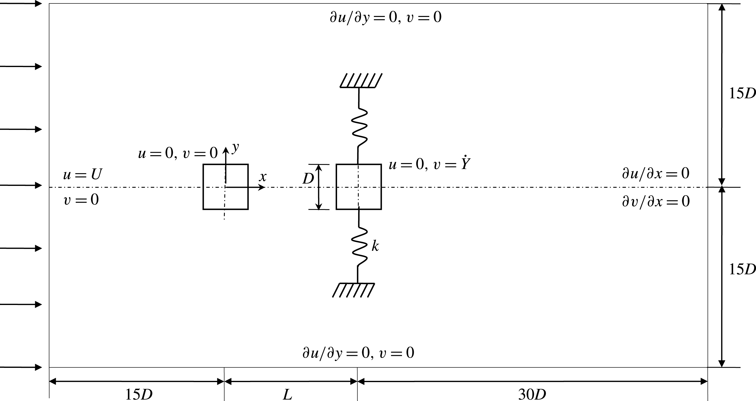
Figure 1. A schematic of the flow configuration and computational domain.
2.1 Governing equations and numerical methods
The governing equations to simulate the flow field are the continuity and Navier–Stokes equations which can be written in non-dimensional form as
 $$\begin{eqnarray}\unicode[STIX]{x1D735}\boldsymbol{\cdot }\boldsymbol{u}=0\end{eqnarray}$$
and
 $$\begin{eqnarray}\frac{\unicode[STIX]{x2202}\boldsymbol{u}}{\unicode[STIX]{x2202}t}+(\boldsymbol{u}\boldsymbol{\cdot }\unicode[STIX]{x1D735})\boldsymbol{u}=-\unicode[STIX]{x1D735}p+\frac{1}{\text{Re}}\unicode[STIX]{x1D6FB}^{2}\boldsymbol{u},\end{eqnarray}$$
where
 $\boldsymbol{u}=(u,v)$
is the velocity field,
$\boldsymbol{u}=(u,v)$
is the velocity field,
 $p$
is the static pressure and
$p$
is the static pressure and
 $t$
is the time. The
$t$
is the time. The
 $D$
and
$D$
and
 $U$
are considered as the reference length and velocity scales respectively for normalization.
$U$
are considered as the reference length and velocity scales respectively for normalization.
The flow at the inlet is set uniform,
 $u=U$
and
$u=U$
and
 $v=0$
. Neumann conditions
$v=0$
. Neumann conditions
 $\unicode[STIX]{x2202}u/\unicode[STIX]{x2202}x=0$
and
$\unicode[STIX]{x2202}u/\unicode[STIX]{x2202}x=0$
and
 $\unicode[STIX]{x2202}v/\unicode[STIX]{x2202}x=0$
are applied at the outlet. Free-slip boundary conditions (
$\unicode[STIX]{x2202}v/\unicode[STIX]{x2202}x=0$
are applied at the outlet. Free-slip boundary conditions (
 $\unicode[STIX]{x2202}u/\unicode[STIX]{x2202}y=0$
and
$\unicode[STIX]{x2202}u/\unicode[STIX]{x2202}y=0$
and
 $v=0$
) are employed for the lateral boundaries, while no-slip conditions are imposed at the cylinder surfaces,
$v=0$
) are employed for the lateral boundaries, while no-slip conditions are imposed at the cylinder surfaces,
 $u=0$
,
$u=0$
,
 $v=0$
for the stationary cylinder and
$v=0$
for the stationary cylinder and
 $u=0$
,
$u=0$
,
 $v={\dot{Y}}$
for the vibrating cylinder.
$v={\dot{Y}}$
for the vibrating cylinder.
The governing equations (2.1) and (2.2) are solved for the unsteady and incompressible flow using the finite-volume-method-based software ANSYS-Fluent 15. The second-order upwind scheme is used to discretize the convective components and the central differencing scheme for diffusion terms. A first-order implicit formulation is adopted for the time discretization due to its unconditional stability (Manson, Pender & Wallis Reference Manson, Pender and Wallis1996) and compatibility with the dynamic mesh (Shaaban & Mohany Reference Shaaban and Mohany2018). The pressure-correction-based iterative algorithm SIMPLE (semi-implicit method for pressure linked equations) proposed by Patankar (Reference Patankar1980) is employed for the coupling between the velocity and pressure fields.
The transverse dynamic response of the cylinder is governed by the following second-order ordinary differential equation in dimensionless form:
 $$\begin{eqnarray}\ddot{Y} +4\unicode[STIX]{x03C0}F_{n}\unicode[STIX]{x1D701}{\dot{Y}}+(2\unicode[STIX]{x03C0}F_{n})^{2}Y=C_{L}/2m^{\ast },\end{eqnarray}$$
where
 $\ddot{Y}$
,
$\ddot{Y}$
,
 ${\dot{Y}}$
and
${\dot{Y}}$
and
 $Y$
are the instantaneous cross-flow acceleration, velocity and displacement of the cylinder respectively, with the
$Y$
are the instantaneous cross-flow acceleration, velocity and displacement of the cylinder respectively, with the
 $Y$
measured from
$Y$
measured from
 $y=0$
. Time is normalized by
$y=0$
. Time is normalized by
 $U$
and
$U$
and
 $D$
. Here,
$D$
. Here,
 $C_{L}$
is the instantaneous lift coefficient of the cylinder and
$C_{L}$
is the instantaneous lift coefficient of the cylinder and
 $F_{n}\;(=f_{n}D/U)$
is the normalized natural frequency of the cylinder. The cylinder mass ratio is defined as
$F_{n}\;(=f_{n}D/U)$
is the normalized natural frequency of the cylinder. The cylinder mass ratio is defined as
 $m^{\ast }=m/\unicode[STIX]{x1D70C}D^{2}$
, where
$m^{\ast }=m/\unicode[STIX]{x1D70C}D^{2}$
, where
 $m$
is the mass of the cylinder per unit length and
$m$
is the mass of the cylinder per unit length and
 $\unicode[STIX]{x1D70C}$
is the density of the fluid. This second-order differential equation is solved using the fourth-order Runge–Kutta method for every time step.
$\unicode[STIX]{x1D70C}$
is the density of the fluid. This second-order differential equation is solved using the fourth-order Runge–Kutta method for every time step.
A dynamic mesh scheme is utilized in the present study. The dynamic mesh model uses the ANSYS-Fluent 15 solver to move boundaries and/or objects and to adjust the mesh accordingly. The oscillating cylinder is surrounded by a grid box of size
 $2D\times 2D$
(figure 2
a). The grid box moves with the vibrating cylinder, while the remaining grids in the domain are stationary. The interface is created by two parallel lines which separate the moving and stationary parts of the domain (figure 2
b). The user defined function is incorporated into the solver for calculating the motion of the oscillating cylinder. At each time step, (i) the deformation of the domain is taken care of by the dynamic meshing tool in ANSYS-Fluent 15 and the mesh is updated using the Laplace smoothing method and (ii) equations (2.1) and (2.2) are solved and the lift force on the cylinder is obtained. The force is used to obtain the response of the oscillating cylinder using (2.3).
$2D\times 2D$
(figure 2
a). The grid box moves with the vibrating cylinder, while the remaining grids in the domain are stationary. The interface is created by two parallel lines which separate the moving and stationary parts of the domain (figure 2
b). The user defined function is incorporated into the solver for calculating the motion of the oscillating cylinder. At each time step, (i) the deformation of the domain is taken care of by the dynamic meshing tool in ANSYS-Fluent 15 and the mesh is updated using the Laplace smoothing method and (ii) equations (2.1) and (2.2) are solved and the lift force on the cylinder is obtained. The force is used to obtain the response of the oscillating cylinder using (2.3).
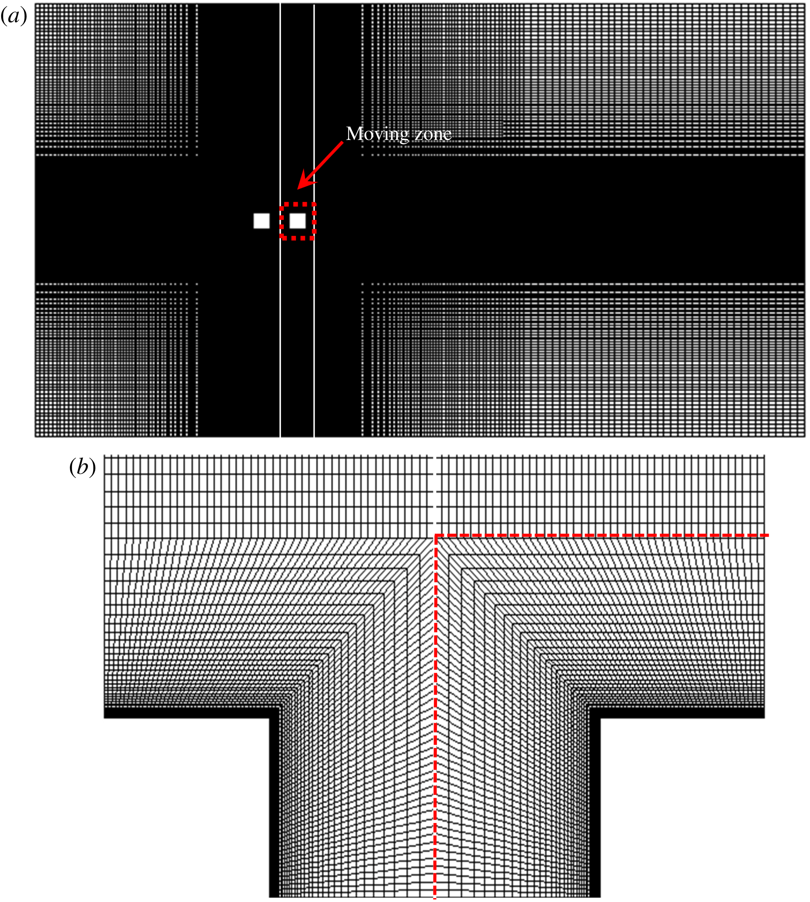
Figure 2. (a) Global view of the meshes around two cylinders at
 $L^{\ast }=2$
. (b) Zoomed-in view of the meshes around the cylinders.
$L^{\ast }=2$
. (b) Zoomed-in view of the meshes around the cylinders.
Structured grids are generated for the whole computational domain using the grid-generating software Gambit. Figure 2 displays the distribution of grids, with a total of 132 542 nodes for
 $L^{\ast }=2$
. The vibrating cylinder is positioned in a square region (
$L^{\ast }=2$
. The vibrating cylinder is positioned in a square region (
 $2D\times 2D$
) enclosed by four interfacing lines that separate the moving and stationary regions. The square region moves with the vibrating cylinder and is given a greater mesh density. The first level of the grid spacing near the cylinder wall is set at
$2D\times 2D$
) enclosed by four interfacing lines that separate the moving and stationary regions. The square region moves with the vibrating cylinder and is given a greater mesh density. The first level of the grid spacing near the cylinder wall is set at
 $0.008D$
away from the cylinder for an adequate resolution of the boundary layer. The grid spacing is then increased with an expansion rate of 1.05 in the normal direction. Following the same expansion factor in the same computation domain, the number of nodes for
$0.008D$
away from the cylinder for an adequate resolution of the boundary layer. The grid spacing is then increased with an expansion rate of 1.05 in the normal direction. Following the same expansion factor in the same computation domain, the number of nodes for
 $L^{\ast }=6$
is increased to 163 568.
$L^{\ast }=6$
is increased to 163 568.
Before conducting extensive simulations, grid and time-step independence tests were carried out for a single square cylinder. Following Sen & Mittal (Reference Sen and Mittal2011), five different meshes in the range of 22 490–100 6152 were tested with
 $\unicode[STIX]{x0394}t=0.01$
, 0.008 and 0.005. Table 1 summarizes the Strouhal number
$\unicode[STIX]{x0394}t=0.01$
, 0.008 and 0.005. Table 1 summarizes the Strouhal number
 $St$
, time-mean drag coefficient
$St$
, time-mean drag coefficient
 $\bar{C}_{D}$
and fluctuating root-mean-square (r.m.s.) lift coefficient
$\bar{C}_{D}$
and fluctuating root-mean-square (r.m.s.) lift coefficient
 $C_{L}^{\prime }$
for the different meshes and time steps used. The percentage deviation with increasing number of nodes is indicated in brackets. The node number 50 350 is approximately half of the finest grid 100 612 considered here. The results are converged at mesh 50 350 and
$C_{L}^{\prime }$
for the different meshes and time steps used. The percentage deviation with increasing number of nodes is indicated in brackets. The node number 50 350 is approximately half of the finest grid 100 612 considered here. The results are converged at mesh 50 350 and
 $\unicode[STIX]{x0394}t=0.008$
.
$\unicode[STIX]{x0394}t=0.008$
.
Table 1. Grid- and time-step-independent study;
 $Re=150$
.
$Re=150$
.

3 Result validation
Validation of the computational approach is provided here along with some benchmark results for a single and two cylinders. The simulated time-mean drag coefficient
 $\bar{C}_{D}$
, fluctuating (r.m.s.) lift coefficient
$\bar{C}_{D}$
, fluctuating (r.m.s.) lift coefficient
 $C_{L}^{\prime }$
and Strouhal number
$C_{L}^{\prime }$
and Strouhal number
 $St$
results for a single fixed cylinder at
$St$
results for a single fixed cylinder at
 $Re=100$
and 200 are compared with those in the literature in table 2. The comparison displays a good agreement.
$Re=100$
and 200 are compared with those in the literature in table 2. The comparison displays a good agreement.
Table 2. Comparison of the results for a fixed single cylinder at
 $Re=100$
and 200.
$Re=100$
and 200.

Figure 3 displays a comparison of
 $\bar{C}_{D}$
acting on a pair of fixed cylinders at various values of
$\bar{C}_{D}$
acting on a pair of fixed cylinders at various values of
 $L^{\ast }$
with results from Inoue, Iwakami & Hatakeyama (Reference Inoue, Iwakami and Hatakeyama2006) and Sohankar (Reference Sohankar2012). While the present results accord well with those from Sohankar (Reference Sohankar2012), Inoue et al.’s (Reference Inoue, Iwakami and Hatakeyama2006) results are underestimated, particularly for the upstream cylinder. A sudden jump in
$L^{\ast }$
with results from Inoue, Iwakami & Hatakeyama (Reference Inoue, Iwakami and Hatakeyama2006) and Sohankar (Reference Sohankar2012). While the present results accord well with those from Sohankar (Reference Sohankar2012), Inoue et al.’s (Reference Inoue, Iwakami and Hatakeyama2006) results are underestimated, particularly for the upstream cylinder. A sudden jump in
 $\bar{C}_{D}$
for both cylinders is observed at
$\bar{C}_{D}$
for both cylinders is observed at
 $4.5<L^{\ast }<5$
, distinguishing the reattachment (figure 3
c) and coshedding (figure 3
d) regimes.
$4.5<L^{\ast }<5$
, distinguishing the reattachment (figure 3
c) and coshedding (figure 3
d) regimes.

Figure 3. Comparison of time-mean drag coefficients for two cylinders at different values of
 $L^{\ast }$
for
$L^{\ast }$
for
 $Re=150$
. (a) Upstream cylinder and (b) downstream cylinder. (c,d) Representative vorticity (
$Re=150$
. (a) Upstream cylinder and (b) downstream cylinder. (c,d) Representative vorticity (
 $\unicode[STIX]{x1D714}_{z}^{\ast }$
) structures in the reattachment (shaded) and coshedding regimes respectively.
$\unicode[STIX]{x1D714}_{z}^{\ast }$
) structures in the reattachment (shaded) and coshedding regimes respectively.
4 Single vibrating cylinder
The vibration response results for a single cylinder are presented in figures 4(a) and 5(a), showing the dependence of
 $A^{\ast }$
on
$A^{\ast }$
on
 $U_{r}$
at
$U_{r}$
at
 $Re=100$
and 200. The
$Re=100$
and 200. The
 $A^{\ast }$
for the cylinder displacement
$A^{\ast }$
for the cylinder displacement
 $Y$
is obtained by multiplying the r.m.s. value of
$Y$
is obtained by multiplying the r.m.s. value of
 $Y$
by
$Y$
by
 $\sqrt{2}$
, i.e.
$\sqrt{2}$
, i.e.
 $A^{\ast }=Y_{rms}\times \sqrt{2}$
, which provides the average amplitude of the cylinder oscillation. The data of Zhao et al. (Reference Zhao, Cheng and Zhou2013) for the same
$A^{\ast }=Y_{rms}\times \sqrt{2}$
, which provides the average amplitude of the cylinder oscillation. The data of Zhao et al. (Reference Zhao, Cheng and Zhou2013) for the same
 $Re$
,
$Re$
,
 $m^{\ast }$
and
$m^{\ast }$
and
 $\unicode[STIX]{x1D701}$
are also included in figure 4(a). The two curves have the same trend, validating our computations for the vibrating cylinder. The maximum amplitude is observed at
$\unicode[STIX]{x1D701}$
are also included in figure 4(a). The two curves have the same trend, validating our computations for the vibrating cylinder. The maximum amplitude is observed at
 $U_{r}\approx 5$
for either curve. Figure 4(b–e) displays vorticity structures at different values of
$U_{r}\approx 5$
for either curve. Figure 4(b–e) displays vorticity structures at different values of
 $U_{r}$
. In order to compare the timing of vortex shedding with respect to the cylinder displacement at different values of
$U_{r}$
. In order to compare the timing of vortex shedding with respect to the cylinder displacement at different values of
 $U_{r}$
, the vorticity structures are given for the cylinder at maximum displacement (
$U_{r}$
, the vorticity structures are given for the cylinder at maximum displacement (
 $Y=Y_{max}$
). As seen in figure 4(a),
$Y=Y_{max}$
). As seen in figure 4(a),
 $A^{\ast }$
is contingent on
$A^{\ast }$
is contingent on
 $U_{r}$
. The cylinder response is divided into three regimes, namely the initial branch (IB), the lower branch (LB) and the desynchronization branch (DB), at
$U_{r}$
. The cylinder response is divided into three regimes, namely the initial branch (IB), the lower branch (LB) and the desynchronization branch (DB), at
 $Re=100$
(figure 4
a). The different branches in the vibration response can be explored through the dependence of
$Re=100$
(figure 4
a). The different branches in the vibration response can be explored through the dependence of
 $St$
on
$St$
on
 $U_{r}$
(figure 4
f). The Strouhal number was estimated from the power spectral density functions of the fluctuating lift forces. Given the fixed cylinder Strouhal number
$U_{r}$
(figure 4
f). The Strouhal number was estimated from the power spectral density functions of the fluctuating lift forces. Given the fixed cylinder Strouhal number
 $St_{0}$
(figure 4
f), it is observed that
$St_{0}$
(figure 4
f), it is observed that
 $St<St_{0}$
in the IB and
$St<St_{0}$
in the IB and
 $St>St_{0}$
in the LB, while
$St>St_{0}$
in the LB, while
 $St\approx St_{0}$
in the DB. The initial branch occurring at
$St\approx St_{0}$
in the DB. The initial branch occurring at
 $U_{r}<4.5$
corresponds to
$U_{r}<4.5$
corresponds to
 $A^{\ast }$
increasing with
$A^{\ast }$
increasing with
 $U_{r}$
. A drastic jump in
$U_{r}$
. A drastic jump in
 $A^{\ast }$
between
$A^{\ast }$
between
 $U_{r}=4.5$
and 5.0 borders the IB and the LB, distinguished by a 2S vortex pattern before the jump (figure 4
b) and a C(2S) vortex pattern after the jump (figure 4
c). With the snapshots given for
$U_{r}=4.5$
and 5.0 borders the IB and the LB, distinguished by a 2S vortex pattern before the jump (figure 4
b) and a C(2S) vortex pattern after the jump (figure 4
c). With the snapshots given for
 $Y=Y_{max}$
, the growing shear layer appears over the upper surface of the cylinder in figure 4(b) and over the lower surface in figure 4(c) (Alam Reference Alam2016). The timing of vortex shedding in the vorticity structures thus reflects that the phase lag between lift and displacement shifts from
$Y=Y_{max}$
, the growing shear layer appears over the upper surface of the cylinder in figure 4(b) and over the lower surface in figure 4(c) (Alam Reference Alam2016). The timing of vortex shedding in the vorticity structures thus reflects that the phase lag between lift and displacement shifts from
 $0^{\circ }$
to
$0^{\circ }$
to
 $180^{\circ }$
between the IB and the LB (figure 4
b,c). The phase lag was also confirmed from the results of cross-correlation between the lift and displacement. In the LB,
$180^{\circ }$
between the IB and the LB (figure 4
b,c). The phase lag was also confirmed from the results of cross-correlation between the lift and displacement. In the LB,
 $A^{\ast }$
drops with increasing
$A^{\ast }$
drops with increasing
 $U_{r}$
, and the vorticity structure changes from C(2S) to 2S with the phase lag unchanged (figure 4
c,d). The LB is followed by the DB, where
$U_{r}$
, and the vorticity structure changes from C(2S) to 2S with the phase lag unchanged (figure 4
c,d). The LB is followed by the DB, where
 $A^{\ast }$
decays and reaches an asymptotic value. The streamwise separation between the vortices thus increases due to the desynchronization (figure 4
e).
$A^{\ast }$
decays and reaches an asymptotic value. The streamwise separation between the vortices thus increases due to the desynchronization (figure 4
e).

Figure 4. (a) Dependence on the reduced velocity
 $U_{r}$
of the vibration amplitude
$U_{r}$
of the vibration amplitude
 $A^{\ast }$
of a single cylinder. (b–e) Typical vorticity (
$A^{\ast }$
of a single cylinder. (b–e) Typical vorticity (
 $\unicode[STIX]{x1D714}_{z}^{\ast }$
) structures in different vibration regimes. (f) Dependence of the Strouhal number
$\unicode[STIX]{x1D714}_{z}^{\ast }$
) structures in different vibration regimes. (f) Dependence of the Strouhal number
 $St$
on
$St$
on
 $U_{r}$
. Here,
$U_{r}$
. Here,
 $Re=100$
.
$Re=100$
.
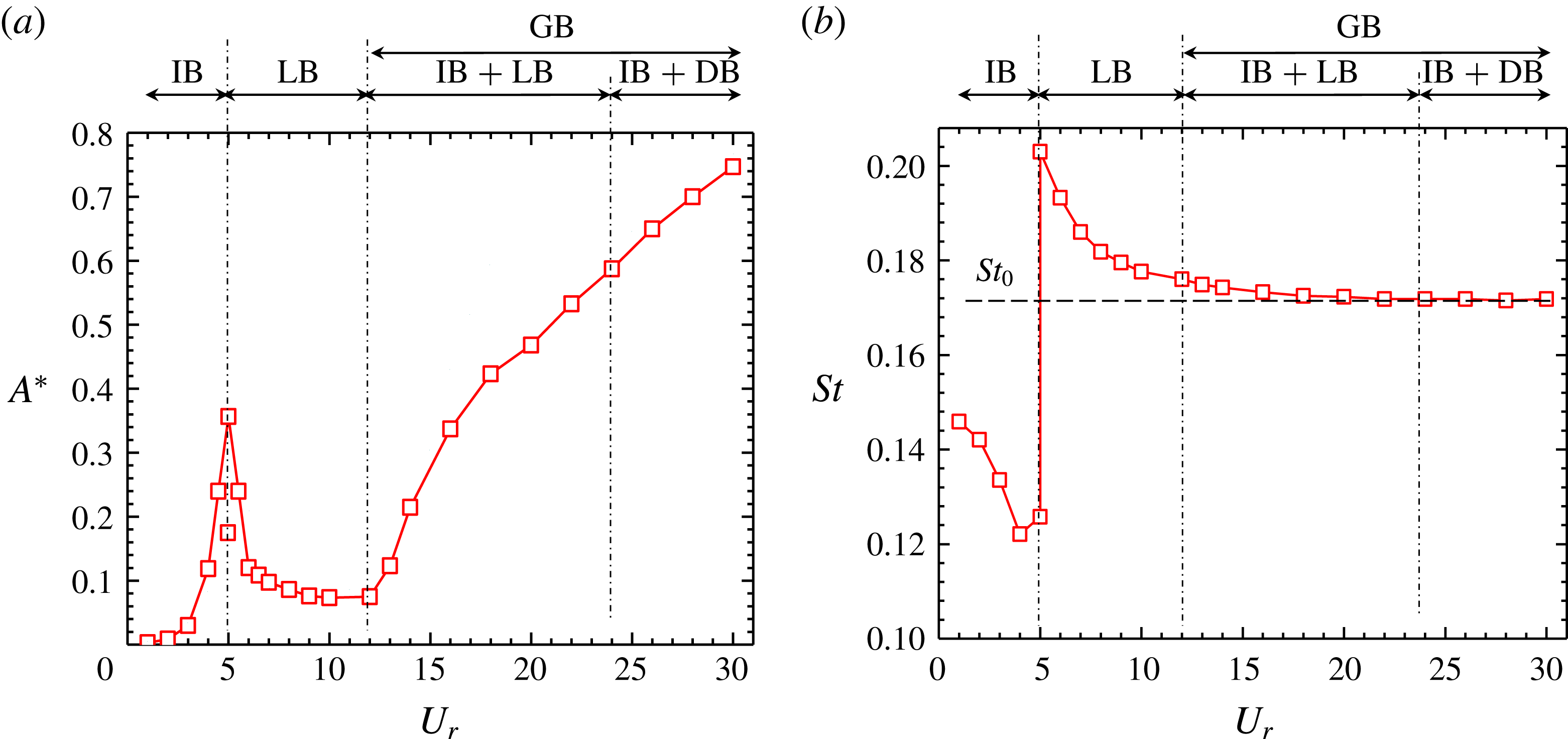
Figure 5. (a) Dependence on the reduced velocity
 $U_{r}$
of the vibration amplitude
$U_{r}$
of the vibration amplitude
 $A^{\ast }$
of a single cylinder. (b) Dependence of the Strouhal number
$A^{\ast }$
of a single cylinder. (b) Dependence of the Strouhal number
 $St$
on
$St$
on
 $U_{r}$
. Here,
$U_{r}$
. Here,
 $Re=200$
.
$Re=200$
.
At
 $Re=200$
(figure 5), a vortex excitation (VE) regime (including the IB and the LB) appears at
$Re=200$
(figure 5), a vortex excitation (VE) regime (including the IB and the LB) appears at
 $U_{r}\leqslant 12$
, while the galloping branch (GB) crops up at
$U_{r}\leqslant 12$
, while the galloping branch (GB) crops up at
 $U_{r}>12$
. It will be shown later that the vibration response at
$U_{r}>12$
. It will be shown later that the vibration response at
 $12<U_{r}<24$
involves the characteristics of both the IB and the LB, and that at
$12<U_{r}<24$
involves the characteristics of both the IB and the LB, and that at
 $U_{r}>24$
the characteristics of both the IB and the DB. While the response characteristics at
$U_{r}>24$
the characteristics of both the IB and the DB. While the response characteristics at
 $U_{r}\leqslant 12$
in the VE regime are akin to those at
$U_{r}\leqslant 12$
in the VE regime are akin to those at
 $Re=100$
, the DB is postponed at
$Re=100$
, the DB is postponed at
 $U_{r}>24$
for
$U_{r}>24$
for
 $Re=200$
. There are two values of
$Re=200$
. There are two values of
 $A^{\ast }$
as well as
$A^{\ast }$
as well as
 $St$
at
$St$
at
 $U_{r}=5$
. It is a transition between the IB and the LB where the two flow modes corresponding to the IB and the LB appear intermittently. More information about the transition will be provided later. Again,
$U_{r}=5$
. It is a transition between the IB and the LB where the two flow modes corresponding to the IB and the LB appear intermittently. More information about the transition will be provided later. Again,
 $St<St_{0}$
at
$St<St_{0}$
at
 $U_{r}<5$
, indicating the IB. On the other hand, at
$U_{r}<5$
, indicating the IB. On the other hand, at
 $5<U_{r}<24$
,
$5<U_{r}<24$
,
 $St>St_{0}$
, which is an indication of the LB. The Strouhal number
$St>St_{0}$
, which is an indication of the LB. The Strouhal number
 $St\approx St_{0}$
at
$St\approx St_{0}$
at
 $U_{r}>24$
, suggesting the DB. Therefore, the vortex shedding frequency characteristics conspicuously distinguish the IB and the LB. The value of
$U_{r}>24$
, suggesting the DB. Therefore, the vortex shedding frequency characteristics conspicuously distinguish the IB and the LB. The value of
 $A^{\ast }$
in the GB increases rather rapidly at
$A^{\ast }$
in the GB increases rather rapidly at
 $12<U_{r}<24$
, and
$12<U_{r}<24$
, and
 $St$
decreases with
$St$
decreases with
 $U_{r}$
, reaching the asymptotic value at
$U_{r}$
, reaching the asymptotic value at
 $U_{r}>24$
. Figure 6 presents the instantaneous vorticity contours along with the time histories of
$U_{r}>24$
. Figure 6 presents the instantaneous vorticity contours along with the time histories of
 $C_{L}$
and
$C_{L}$
and
 $Y$
for
$Y$
for
 $U_{r}=3$
, 4, 5, 9 and 20. Again, the vorticity snapshots are given for the same phase (
$U_{r}=3$
, 4, 5, 9 and 20. Again, the vorticity snapshots are given for the same phase (
 $Y=Y_{max}$
). The
$Y=Y_{max}$
). The
 $C_{L}$
and
$C_{L}$
and
 $Y$
signals are in phase in the IB (figure 6
$Y$
signals are in phase in the IB (figure 6
 $\mathit{a}_{1}$
), and a 2S type vortex street materializes in the wake (figure 6
$\mathit{a}_{1}$
), and a 2S type vortex street materializes in the wake (figure 6
 $\mathit{a}_{2}$
). For a value of
$\mathit{a}_{2}$
). For a value of
 $U_{r}$
near the boundary between the IB and the LB, irregularity may occur in both signals (Navrose & Mittal Reference Mittal2017). At
$U_{r}$
near the boundary between the IB and the LB, irregularity may occur in both signals (Navrose & Mittal Reference Mittal2017). At
 $U_{r}=4$
, the vortex shedding occurs in the 2S mode but the streamwise separation between two consecutive vortices differs (figure 6
$U_{r}=4$
, the vortex shedding occurs in the 2S mode but the streamwise separation between two consecutive vortices differs (figure 6
 $\mathit{b}_{3}$
). As such, a beat in the
$\mathit{b}_{3}$
). As such, a beat in the
 $C_{L}$
and
$C_{L}$
and
 $Y$
histories is discernible (figure 6
$Y$
histories is discernible (figure 6
 $\mathit{b}_{1},\!\mathit{b}_{2}$
); the
$\mathit{b}_{1},\!\mathit{b}_{2}$
); the
 $C_{L}$
as well as the
$C_{L}$
as well as the
 $Y$
amplitude is not constant, becoming large and small alternately following a period. Interestingly, a large peak corresponds to
$Y$
amplitude is not constant, becoming large and small alternately following a period. Interestingly, a large peak corresponds to
 $C_{L}$
leading
$C_{L}$
leading
 $Y$
(figure 6
$Y$
(figure 6
 $\mathit{b}_{2}$
), whereas
$\mathit{b}_{2}$
), whereas
 $C_{L}$
lags
$C_{L}$
lags
 $Y$
for a small peak. When
$Y$
for a small peak. When
 $C_{L}$
leads
$C_{L}$
leads
 $Y$
, positive work is done on the cylinder, which, gaining energy from the flow, can reach a large amplitude. On the contrary, when
$Y$
, positive work is done on the cylinder, which, gaining energy from the flow, can reach a large amplitude. On the contrary, when
 $C_{L}$
lags
$C_{L}$
lags
 $Y$
, the gained energy of the cylinder is released into the flow (negative work); hence, the amplitude gets smaller. For
$Y$
, the gained energy of the cylinder is released into the flow (negative work); hence, the amplitude gets smaller. For
 $U_{r}=5$
, the
$U_{r}=5$
, the
 $C_{L}$
and
$C_{L}$
and
 $Y$
signals comprise two intermittent modes (figure 6
c). Between the two modes, the maximum amplitude of
$Y$
signals comprise two intermittent modes (figure 6
c). Between the two modes, the maximum amplitude of
 $Y$
varies from 0.175 to 0.35 and that of
$Y$
varies from 0.175 to 0.35 and that of
 $C_{L}$
from 0.01 to 2.2. The high- and low-amplitude modes correspond to a low and a high oscillation frequency respectively (figure 6
$C_{L}$
from 0.01 to 2.2. The high- and low-amplitude modes correspond to a low and a high oscillation frequency respectively (figure 6
 $\mathit{c}_{1}$
). The flow mode associated with the high amplitude (figure 6
$\mathit{c}_{1}$
). The flow mode associated with the high amplitude (figure 6
 $\mathit{c}_{1},\!\mathit{c}_{2}$
) is similar to the flow mode at
$\mathit{c}_{1},\!\mathit{c}_{2}$
) is similar to the flow mode at
 $U_{r}=4$
(figure 6
$U_{r}=4$
(figure 6
 $\mathit{b}_{3}$
). For the small-amplitude mode (figure 6
$\mathit{b}_{3}$
). For the small-amplitude mode (figure 6
 $\mathit{c}_{3}$
), a double-row vortex street in the C(2S) mode characterizes the wake. The phase lag between
$\mathit{c}_{3}$
), a double-row vortex street in the C(2S) mode characterizes the wake. The phase lag between
 $C_{L}$
and
$C_{L}$
and
 $Y$
is almost
$Y$
is almost
 ${\approx}0^{\circ }$
and
${\approx}0^{\circ }$
and
 $180^{\circ }$
in the large- and small-amplitude modes respectively. At
$180^{\circ }$
in the large- and small-amplitude modes respectively. At
 $U_{r}>5$
, the phase lag is
$U_{r}>5$
, the phase lag is
 $180^{\circ }$
(figure 6
d).
$180^{\circ }$
(figure 6
d).
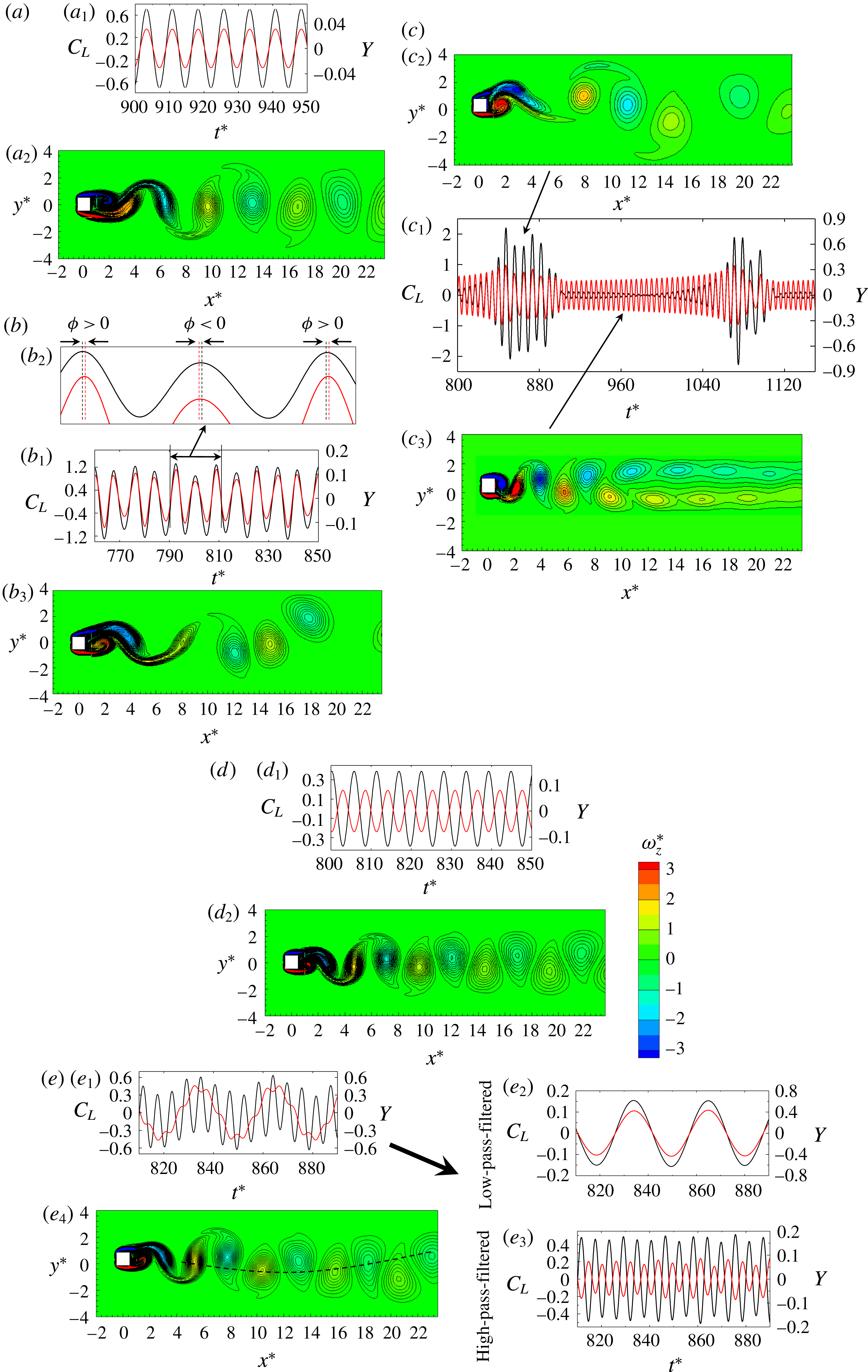
Figure 6. Time histories of the lift force coefficient
 $C_{L}$
(black lines) and the displacement
$C_{L}$
(black lines) and the displacement
 $Y$
(red lines), and representative vorticity (
$Y$
(red lines), and representative vorticity (
 $\unicode[STIX]{x1D714}_{z}^{\ast }$
) structures for
$\unicode[STIX]{x1D714}_{z}^{\ast }$
) structures for
 $U_{r}=$
(a) 3, (b) 4, (c) 5, (d) 9 and (e) 20. Here,
$U_{r}=$
(a) 3, (b) 4, (c) 5, (d) 9 and (e) 20. Here,
 $Re=200$
.
$Re=200$
.
Galloping is a structural instability phenomenon associated with a large amplitude and a low vibration frequency, prevailing for the non-circular cross-section (Blevins Reference Blevins1990). Presently, the galloping vibration occurs at
 $U_{r}>12$
(figure 5
a). Let us pay attention to the response and
$U_{r}>12$
(figure 5
a). Let us pay attention to the response and
 $C_{L}$
signals at
$C_{L}$
signals at
 $U_{r}=20$
(figure 6
e) in the GB. Evidently, the predominant period of the cylinder oscillation is longer than the vortex shedding period (figure 6
$U_{r}=20$
(figure 6
e) in the GB. Evidently, the predominant period of the cylinder oscillation is longer than the vortex shedding period (figure 6
 $\mathit{e}_{1}$
), the oscillation frequency being smaller than the shedding frequency. Both the lift and the displacement signals are composed of low- and high-frequency components (figure 6
$\mathit{e}_{1}$
), the oscillation frequency being smaller than the shedding frequency. Both the lift and the displacement signals are composed of low- and high-frequency components (figure 6
 $\mathit{e}_{1}$
). These low- and high-frequency components were decomposed using the FFT-filter tool in the origin pro software. The cutoff frequency for the decomposition was chosen as the average of the high and low frequencies. The decomposed signals are presented in figure 6(
$\mathit{e}_{1}$
). These low- and high-frequency components were decomposed using the FFT-filter tool in the origin pro software. The cutoff frequency for the decomposition was chosen as the average of the high and low frequencies. The decomposed signals are presented in figure 6(
 $\mathit{e}_{2},\!\mathit{e}_{3}$
). Govardhan & Williamson (Reference Govardhan and Williamson2000) and Ludlam, Gil & Velazquez (Reference Ludlam, Gil and Velazquez2017) decomposed the lift force into potential and vortex forces. The potential force is the inertia force due to the potential added mass. They obtained the potential force as the minus acceleration times the mass of the fluid displaced by the cylinder. The phase lag between the potential force and the displacement is thus
$\mathit{e}_{2},\!\mathit{e}_{3}$
). Govardhan & Williamson (Reference Govardhan and Williamson2000) and Ludlam, Gil & Velazquez (Reference Ludlam, Gil and Velazquez2017) decomposed the lift force into potential and vortex forces. The potential force is the inertia force due to the potential added mass. They obtained the potential force as the minus acceleration times the mass of the fluid displaced by the cylinder. The phase lag between the potential force and the displacement is thus
 $0^{\circ }$
(inphase), and the frequency in the potential force is the same as that in the displacement signal. On the other hand, the frequency in the vortex force follows the vortex formation frequency. They used phase information on the forces to classify the different branches in the VE regime where the cylinder vibrates at one frequency. In the galloping regime of our study, the cylinder oscillates at two frequencies, corresponding to the cylinder natural frequency and the vortex shedding frequency. In order to get a clear phase relationship between the lift and the displacement, the signals of the lift and the displacement should have one identical frequency. Therefore, we decomposed the low- and high-frequency components of the lift and displacement signals in order to find the phase relationships between the lift and the displacement at low- and high-frequency components of oscillations separately.
$0^{\circ }$
(inphase), and the frequency in the potential force is the same as that in the displacement signal. On the other hand, the frequency in the vortex force follows the vortex formation frequency. They used phase information on the forces to classify the different branches in the VE regime where the cylinder vibrates at one frequency. In the galloping regime of our study, the cylinder oscillates at two frequencies, corresponding to the cylinder natural frequency and the vortex shedding frequency. In order to get a clear phase relationship between the lift and the displacement, the signals of the lift and the displacement should have one identical frequency. Therefore, we decomposed the low- and high-frequency components of the lift and displacement signals in order to find the phase relationships between the lift and the displacement at low- and high-frequency components of oscillations separately.
Interestingly, the low- and high-pass-filtered
 $C_{L}$
and
$C_{L}$
and
 $Y$
signals (figure 6
$Y$
signals (figure 6
 $\mathit{e}_{2},\!\mathit{e}_{3}$
) show that the low-frequency
$\mathit{e}_{2},\!\mathit{e}_{3}$
) show that the low-frequency
 $Y$
is dominant and in phase with the low-frequency
$Y$
is dominant and in phase with the low-frequency
 $C_{L}$
, the amplitude of which is very small. On the other hand, the high-frequency
$C_{L}$
, the amplitude of which is very small. On the other hand, the high-frequency
 $Y$
is small and antiphase with the corresponding
$Y$
is small and antiphase with the corresponding
 $C_{L}$
, having a high amplitude. That is, the high-frequency oscillation and shedding have characteristics similar to those in the LB, given
$C_{L}$
, having a high amplitude. That is, the high-frequency oscillation and shedding have characteristics similar to those in the LB, given
 $St>St_{0}$
(figure 5
b) and the phase lag
$St>St_{0}$
(figure 5
b) and the phase lag
 $180^{\circ }$
between
$180^{\circ }$
between
 $C_{L}$
and
$C_{L}$
and
 $Y$
. The large-amplitude vibration associated with the low frequency is essentially the galloping vibration, bearing similar characteristics to those of the IB, given that
$Y$
. The large-amplitude vibration associated with the low frequency is essentially the galloping vibration, bearing similar characteristics to those of the IB, given that
 $St<St_{0}$
and the phase lag is
$St<St_{0}$
and the phase lag is
 $0^{\circ }$
between
$0^{\circ }$
between
 $C_{L}$
and
$C_{L}$
and
 $Y$
(figure 6
$Y$
(figure 6
 $\mathit{e}_{2}$
). The galloping vibration in
$\mathit{e}_{2}$
). The galloping vibration in
 $12<U_{r}<24$
is thus a combination of the IB and the LB, albeit
$12<U_{r}<24$
is thus a combination of the IB and the LB, albeit
 $A^{\ast }$
is predominantly associated with the former. At
$A^{\ast }$
is predominantly associated with the former. At
 $U_{r}>24$
, the low-frequency
$U_{r}>24$
, the low-frequency
 $C_{L}$
and
$C_{L}$
and
 $Y$
do not differ from those at
$Y$
do not differ from those at
 $12<U_{r}<24$
, but the high-frequency
$12<U_{r}<24$
, but the high-frequency
 $C_{L}$
and
$C_{L}$
and
 $Y$
correspond to
$Y$
correspond to
 $St\approx St_{0}$
(figure 5
b). Thus, the galloping at
$St\approx St_{0}$
(figure 5
b). Thus, the galloping at
 $U_{r}>24$
is a combination of the IB and the DB. Yet, the wake resembles 2S vortex streets (figure 7). It should be noted that the low-frequency
$U_{r}>24$
is a combination of the IB and the DB. Yet, the wake resembles 2S vortex streets (figure 7). It should be noted that the low-frequency
 $C_{L}$
stems from the low-frequency wave (dashed line, figure 6
$C_{L}$
stems from the low-frequency wave (dashed line, figure 6
 $\mathit{e}_{4}$
) of the vortex street following the cylinder oscillation. In summary, the galloping vibration resembles the IB in the sense that the predominant vibration amplitude grows with
$\mathit{e}_{4}$
) of the vortex street following the cylinder oscillation. In summary, the galloping vibration resembles the IB in the sense that the predominant vibration amplitude grows with
 $U_{r}$
, both following the same
$U_{r}$
, both following the same
 $Y$
–
$Y$
–
 $C_{L}$
phase relationship.
$C_{L}$
phase relationship.
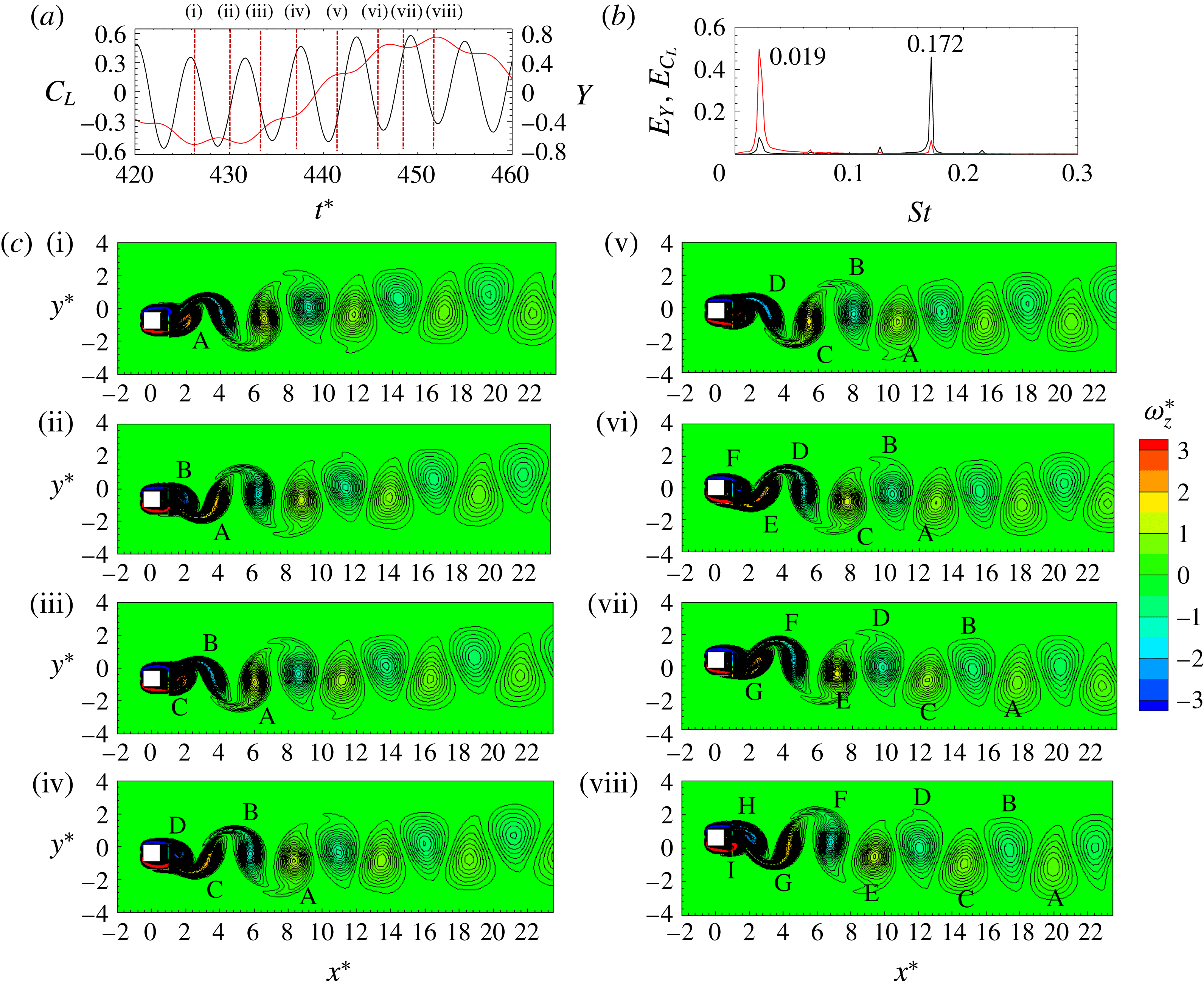
Figure 7. (a) Time histories of
 $Y$
(red line) and
$Y$
(red line) and
 $C_{L}$
(black line). (b) Corresponding spectra. (c) Instantaneous vorticity (
$C_{L}$
(black line). (b) Corresponding spectra. (c) Instantaneous vorticity (
 $\unicode[STIX]{x1D714}_{z}^{\ast }$
) contours at the timings marked at the top of (a). Here,
$\unicode[STIX]{x1D714}_{z}^{\ast }$
) contours at the timings marked at the top of (a). Here,
 $U_{r}=30$
and
$U_{r}=30$
and
 $Re=200$
.
$Re=200$
.
Figure 7 shows the time histories of
 $C_{L}$
and
$C_{L}$
and
 $Y$
(figure 7
a), the power spectra
$Y$
(figure 7
a), the power spectra
 $E_{CL}$
and
$E_{CL}$
and
 $E_{Y}$
for
$E_{Y}$
for
 $C_{L}$
and
$C_{L}$
and
 $Y$
respectively (figure 7
b), and the vortex structures (figure 7
c) for a half cylinder-oscillation cycle for
$Y$
respectively (figure 7
b), and the vortex structures (figure 7
c) for a half cylinder-oscillation cycle for
 $U_{r}=30$
. The corresponding timing of each snapshot in figure 7(c) is marked by a vertical dashed line in figure 7(a). The
$U_{r}=30$
. The corresponding timing of each snapshot in figure 7(c) is marked by a vertical dashed line in figure 7(a). The
 $C_{L}$
and
$C_{L}$
and
 $Y$
histories each consist of a low and a high frequency. The low and high frequencies are dominant in
$Y$
histories each consist of a low and a high frequency. The low and high frequencies are dominant in
 $Y$
and
$Y$
and
 $C_{L}$
respectively, as further evidenced by the power spectra in figure 7(b). The values of the dominant Strouhal numbers are 0.172 and 0.019 for
$C_{L}$
respectively, as further evidenced by the power spectra in figure 7(b). The values of the dominant Strouhal numbers are 0.172 and 0.019 for
 $C_{L}$
and
$C_{L}$
and
 $Y$
respectively, suggesting that the vortex shedding occurs at
$Y$
respectively, suggesting that the vortex shedding occurs at
 $St=0.172$
while the cylinder oscillation dominantly succeeds at
$St=0.172$
while the cylinder oscillation dominantly succeeds at
 $St=0.019$
. The vortex shedding and wake structures in figure 7(c) reveal that, as the cylinder moves from its bottom position to the top (instants (i–viii)), a total of nine vortices (marked as ‘A’–‘I’) are formed (four from the upper side and five from the lower side) in a half cylinder-oscillation cycle. Similarly, when cylinder moves from the top to the bottom, another nine vortices come into being (not shown here). Therefore, the total number of shed vortices during an oscillation cycle is 18. This indicates that the vortex shedding mode is
$St=0.019$
. The vortex shedding and wake structures in figure 7(c) reveal that, as the cylinder moves from its bottom position to the top (instants (i–viii)), a total of nine vortices (marked as ‘A’–‘I’) are formed (four from the upper side and five from the lower side) in a half cylinder-oscillation cycle. Similarly, when cylinder moves from the top to the bottom, another nine vortices come into being (not shown here). Therefore, the total number of shed vortices during an oscillation cycle is 18. This indicates that the vortex shedding mode is
 $N$
(2S) (e.g. 9(2S) here), with the wake appearing similar to the 2S shedding mode.
$N$
(2S) (e.g. 9(2S) here), with the wake appearing similar to the 2S shedding mode.
5 Tandem cylinders
Here, results for the tandem cylinder case are presented at
 $L^{\ast }=2$
and 6 for
$L^{\ast }=2$
and 6 for
 $Re=100$
and 200, where the upstream cylinder is fixed and the downstream cylinder is free to vibrate.
$Re=100$
and 200, where the upstream cylinder is fixed and the downstream cylinder is free to vibrate.

Figure 8. Variation in the vibration amplitude
 $A^{\ast }$
with the reduced velocity
$A^{\ast }$
with the reduced velocity
 $U_{r}$
at (a)
$U_{r}$
at (a)
 $Re=100$
and (b)
$Re=100$
and (b)
 $Re=200$
. Here,
$Re=200$
. Here,
 $L^{\ast }=2$
.
$L^{\ast }=2$
.
5.1 Reattachment regime (
 $L^{\ast }=2$
)
$L^{\ast }=2$
)

5.1.1 Vibration response
Figure 8 shows the dependence of
 $A^{\ast }$
on
$A^{\ast }$
on
 $U_{r}$
at
$U_{r}$
at
 $Re=100$
and 200. The single-cylinder response included in the figure distinguishes how the presence of the fixed upstream cylinder influences the response of the downstream cylinder. The downstream cylinder hereafter will be referred to as the wake cylinder. The vibration classifications given at the top of and in the figure are for the single and wake cylinders respectively. At
$Re=100$
and 200. The single-cylinder response included in the figure distinguishes how the presence of the fixed upstream cylinder influences the response of the downstream cylinder. The downstream cylinder hereafter will be referred to as the wake cylinder. The vibration classifications given at the top of and in the figure are for the single and wake cylinders respectively. At
 $Re=100$
(figure 8
a), the IB is delayed for the wake cylinder compared with the single-cylinder counterpart. The delay is attributed to the shear-layer reattachment (figure 3
c), which results in a smaller
$Re=100$
(figure 8
a), the IB is delayed for the wake cylinder compared with the single-cylinder counterpart. The delay is attributed to the shear-layer reattachment (figure 3
c), which results in a smaller
 $St$
for tandem fixed cylinders (Alam et al.
Reference Alam, Moriya, Takai and Sakamoto2002; Zheng & Alam Reference Zheng and Alam2018). A higher
$St$
for tandem fixed cylinders (Alam et al.
Reference Alam, Moriya, Takai and Sakamoto2002; Zheng & Alam Reference Zheng and Alam2018). A higher
 $U_{r}$
is thus required to make
$U_{r}$
is thus required to make
 $f_{v}=f_{n}$
. The increase in
$f_{v}=f_{n}$
. The increase in
 $A^{\ast }$
in the IB for the wake cylinder is very small compared with that for the single cylinder. The
$A^{\ast }$
in the IB for the wake cylinder is very small compared with that for the single cylinder. The
 $A^{\ast }$
, which is maximum at
$A^{\ast }$
, which is maximum at
 $U_{r}=6.5$
, reduces with an increase in
$U_{r}=6.5$
, reduces with an increase in
 $U_{r}$
. The fashion of the reduction after the maximum
$U_{r}$
. The fashion of the reduction after the maximum
 $A^{\ast }$
for the wake cylinder is, however, different from that for the single cylinder. The reduction for the single cylinder is rapid at
$A^{\ast }$
for the wake cylinder is, however, different from that for the single cylinder. The reduction for the single cylinder is rapid at
 $U_{r}=5{-}10$
(LB regime) but slow at
$U_{r}=5{-}10$
(LB regime) but slow at
 $U_{r}>10$
(DB regime). The rapid reduction is, on the other hand, absent for the wake cylinder, the amplitude waning monotonically in a longer LB regime compared with the single-cylinder counterpart. In the DB regime as well,
$U_{r}>10$
(DB regime). The rapid reduction is, on the other hand, absent for the wake cylinder, the amplitude waning monotonically in a longer LB regime compared with the single-cylinder counterpart. In the DB regime as well,
 $A^{\ast }$
remains higher for the wake cylinder.
$A^{\ast }$
remains higher for the wake cylinder.
As
 $Re$
is increased from 100 to 200 (figure 8
b), the vibration response characteristics of the wake cylinder in the IB remain unchanged. The LB of the wake cylinder exhibits a rather more rapid decrease in
$Re$
is increased from 100 to 200 (figure 8
b), the vibration response characteristics of the wake cylinder in the IB remain unchanged. The LB of the wake cylinder exhibits a rather more rapid decrease in
 $A^{\ast }$
for
$A^{\ast }$
for
 $Re=200$
than
$Re=200$
than
 $Re=100$
. The
$Re=100$
. The
 $U_{r}$
corresponding to the initiation (maximum
$U_{r}$
corresponding to the initiation (maximum
 $A^{\ast }$
) of the LB decreases from
$A^{\ast }$
) of the LB decreases from
 $U_{r}=6.5$
to 5.5 as
$U_{r}=6.5$
to 5.5 as
 $Re$
is increased from 100 to 200. A further increase in
$Re$
is increased from 100 to 200. A further increase in
 $U_{r}$
from the LB to the DB results in a gradual decay of
$U_{r}$
from the LB to the DB results in a gradual decay of
 $A^{\ast }$
to be more or less constant at 0.07 at
$A^{\ast }$
to be more or less constant at 0.07 at
 $U_{r}\geqslant 20$
. For the single cylinder, the
$U_{r}\geqslant 20$
. For the single cylinder, the
 $A^{\ast }$
drop is relatively sharp in the early stage of the LB, followed by
$A^{\ast }$
drop is relatively sharp in the early stage of the LB, followed by
 $A^{\ast }$
increasing in the GB regime (
$A^{\ast }$
increasing in the GB regime (
 $U_{r}>12$
). Interestingly, although the single cylinder experiences galloping, the wake cylinder does not. That is, when the single cylinder at
$U_{r}>12$
). Interestingly, although the single cylinder experiences galloping, the wake cylinder does not. That is, when the single cylinder at
 $Re=200$
exhibits IB, LB and GB responses (figure 5
a), the wake cylinder undergoes IB, LB and DB responses. The GB is absent for the latter. In addition, the
$Re=200$
exhibits IB, LB and GB responses (figure 5
a), the wake cylinder undergoes IB, LB and DB responses. The GB is absent for the latter. In addition, the
 $U_{r}$
ranges of the different branches differ between the single and wake cylinders. These observations show that the knowledge on the single cylinder cannot be extrapolated for two cylinders. In the reattachment regime, the wake cylinder is encapsulated by the shear layers from the upstream cylinder. Due to the insufficient spacing between the cylinders and the shear layers largely reattaching on the side surfaces, the flow in the gap is small. The reattached shear layer may restrict the motion of the cylinder.
$U_{r}$
ranges of the different branches differ between the single and wake cylinders. These observations show that the knowledge on the single cylinder cannot be extrapolated for two cylinders. In the reattachment regime, the wake cylinder is encapsulated by the shear layers from the upstream cylinder. Due to the insufficient spacing between the cylinders and the shear layers largely reattaching on the side surfaces, the flow in the gap is small. The reattached shear layer may restrict the motion of the cylinder.
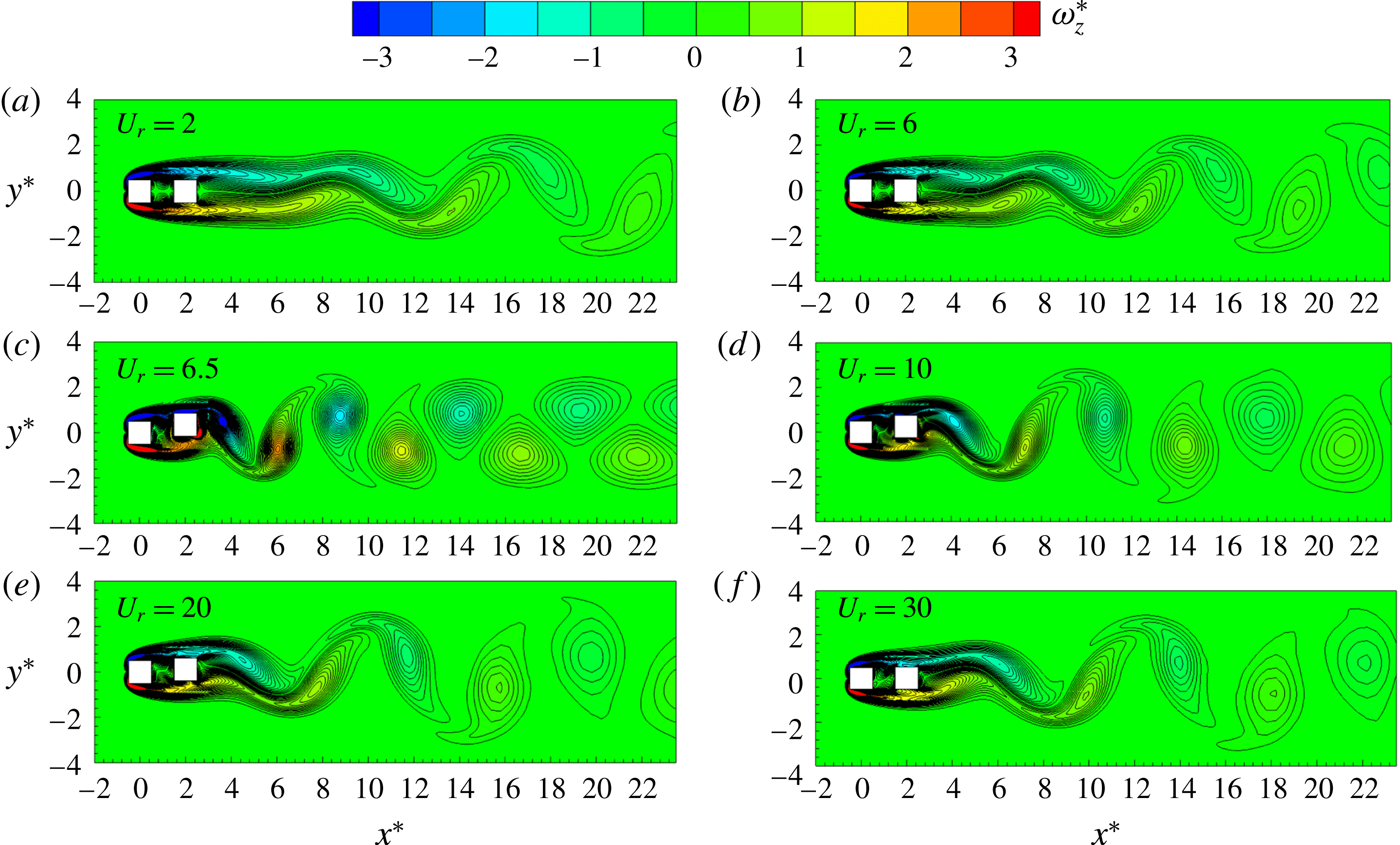
Figure 9. Instantaneous vorticity (
 $\unicode[STIX]{x1D714}_{z}^{\ast }$
) structures at various values of
$\unicode[STIX]{x1D714}_{z}^{\ast }$
) structures at various values of
 $U_{r}$
. The instant of the snapshots corresponds to
$U_{r}$
. The instant of the snapshots corresponds to
 $Y=Y_{max}$
. Here,
$Y=Y_{max}$
. Here,
 $L^{\ast }=2$
and
$L^{\ast }=2$
and
 $Re=100$
.
$Re=100$
.
5.1.2 Wake structures
Figure 9 shows the instantaneous vorticity contours at different values of
 $U_{r}$
for
$U_{r}$
for
 $Re=100$
. The vorticity structures correspond to the instant
$Re=100$
. The vorticity structures correspond to the instant
 $Y=Y_{max}$
. For the IB (figure 9
a,b), the two shear layers separating from the upstream cylinder reattach almost steadily on the wake cylinder, forming a quasisteady flow region in the gap between the cylinders. Vortices shed only from the wake cylinder. With an increase in
$Y=Y_{max}$
. For the IB (figure 9
a,b), the two shear layers separating from the upstream cylinder reattach almost steadily on the wake cylinder, forming a quasisteady flow region in the gap between the cylinders. Vortices shed only from the wake cylinder. With an increase in
 $U_{r}$
from 2 to 6, the roll-up of the vortices shifts upstream, indicating that the formation length shrinks. The wake cylinder is encapsulated by the shear layers from the upstream cylinder. Due to this encapsulation, the fluctuating lift force on the wake cylinder is reduced compared with that on the single cylinder, leading to a small value of
$U_{r}$
from 2 to 6, the roll-up of the vortices shifts upstream, indicating that the formation length shrinks. The wake cylinder is encapsulated by the shear layers from the upstream cylinder. Due to this encapsulation, the fluctuating lift force on the wake cylinder is reduced compared with that on the single cylinder, leading to a small value of
 $A^{\ast }$
in the IB regime for the wake cylinder (figure 8
a). Comparing the fluctuating lift and the maximum amplitude of the downstream cylinder, Alam & Kim (Reference Alam and Kim2009) and Kim et al. (Reference Kim, Alam, Sakamoto and Zhou2009), for two circular cylinders, concluded that the maximum amplitude of the downstream cylinder follows the fluctuating lift measured on the stationary downstream cylinder. Qin, Alam & Zhou (Reference Qin, Alam and Zhou2017), for two tandem circular cylinders of different diameters, found that an increase in
$A^{\ast }$
in the IB regime for the wake cylinder (figure 8
a). Comparing the fluctuating lift and the maximum amplitude of the downstream cylinder, Alam & Kim (Reference Alam and Kim2009) and Kim et al. (Reference Kim, Alam, Sakamoto and Zhou2009), for two circular cylinders, concluded that the maximum amplitude of the downstream cylinder follows the fluctuating lift measured on the stationary downstream cylinder. Qin, Alam & Zhou (Reference Qin, Alam and Zhou2017), for two tandem circular cylinders of different diameters, found that an increase in
 $A^{\ast }$
results from an increased fluctuating lift when the phase lag between
$A^{\ast }$
results from an increased fluctuating lift when the phase lag between
 $Y$
and
$Y$
and
 $C_{L}$
does not change much, or when the inertia force is small due to small amplitude and frequency (Govardhan & Williamson Reference Govardhan and Williamson2000). The phase lag between the lift and the displacement is
$C_{L}$
does not change much, or when the inertia force is small due to small amplitude and frequency (Govardhan & Williamson Reference Govardhan and Williamson2000). The phase lag between the lift and the displacement is
 $0^{\circ }$
, as can be seen from the timing of vortex shedding at
$0^{\circ }$
, as can be seen from the timing of vortex shedding at
 $Y=Y_{max}$
(figure 9
a,b). With an increase in
$Y=Y_{max}$
(figure 9
a,b). With an increase in
 $U_{r}$
from the IB to the LB (figure 9
c), the flow in the gap becomes unsteady, as the two upstream-cylinder-generated shear layers reattach alternately on the upper and lower side surfaces of the wake cylinder. The phase lag becomes
$U_{r}$
from the IB to the LB (figure 9
c), the flow in the gap becomes unsteady, as the two upstream-cylinder-generated shear layers reattach alternately on the upper and lower side surfaces of the wake cylinder. The phase lag becomes
 $180^{\circ }$
. The longitudinal spacing between two consecutive vortices becomes small. The small spacing between two consecutive vortices can be ascribed to the increased
$180^{\circ }$
. The longitudinal spacing between two consecutive vortices becomes small. The small spacing between two consecutive vortices can be ascribed to the increased
 $St$
from the IB to the LB (figure 4
f). An increased
$St$
from the IB to the LB (figure 4
f). An increased
 $St$
means that a vortex has a shorter time to convect downstream before the next vortex coming into the street and vice versa. As
$St$
means that a vortex has a shorter time to convect downstream before the next vortex coming into the street and vice versa. As
 $A^{\ast }$
decays from
$A^{\ast }$
decays from
 $U_{r}=6.5$
to 20 (figure 8
a), the shear-layer rolling is postponed and the streamwise separation between the vortices is elongated (figure 9
c–e). Again, the elongated separation between the vortices is linked to the decrease in
$U_{r}=6.5$
to 20 (figure 8
a), the shear-layer rolling is postponed and the streamwise separation between the vortices is elongated (figure 9
c–e). Again, the elongated separation between the vortices is linked to the decrease in
 $St$
with
$St$
with
 $U_{r}$
(figure 4
f). In the DB regime, where
$U_{r}$
(figure 4
f). In the DB regime, where
 $A^{\ast }$
is small, a further postponement in the shear-layer rolling takes place (figure 9
f).
$A^{\ast }$
is small, a further postponement in the shear-layer rolling takes place (figure 9
f).
Figure 10 shows the instantaneous vorticity contours at
 $Re=200$
. A similar observation is made for the IB (figure 10
a,b) as made for
$Re=200$
. A similar observation is made for the IB (figure 10
a,b) as made for
 $Re=100$
(figure 9
a,b). The vortex shedding, however, occurs closer to the cylinder at
$Re=100$
(figure 9
a,b). The vortex shedding, however, occurs closer to the cylinder at
 $Re=200$
than at
$Re=200$
than at
 $Re=100$
. The wake is characterized by the 2S mode. A C(2S) mode appears at
$Re=100$
. The wake is characterized by the 2S mode. A C(2S) mode appears at
 $U_{r}=5.5$
(figure 10
c) where
$U_{r}=5.5$
(figure 10
c) where
 $A^{\ast }$
is maximum in the LB. However, as
$A^{\ast }$
is maximum in the LB. However, as
 $U_{r}$
is increased, the wake turns into a 2S mode (figure 10
d,e). In the DB, the vortex formation length and streamwise separation between vortices are both elongated (figure 10
f).
$U_{r}$
is increased, the wake turns into a 2S mode (figure 10
d,e). In the DB, the vortex formation length and streamwise separation between vortices are both elongated (figure 10
f).
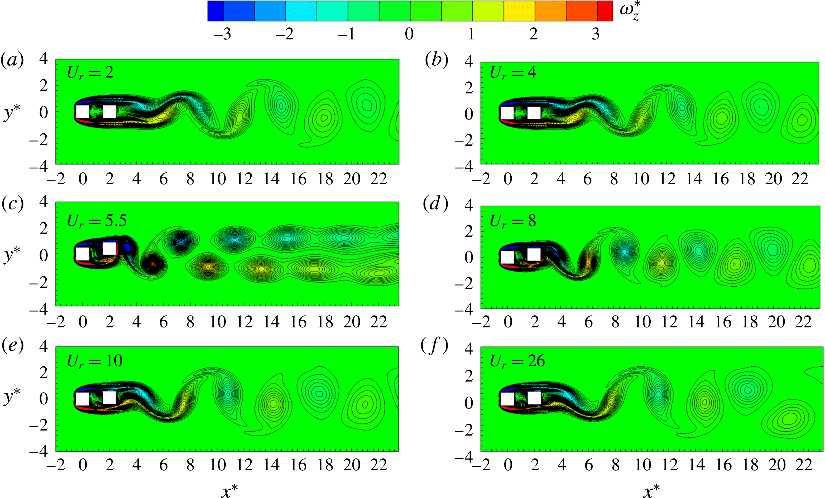
Figure 10. Instantaneous vorticity (
 $\unicode[STIX]{x1D714}_{z}^{\ast }$
) structures at different values of
$\unicode[STIX]{x1D714}_{z}^{\ast }$
) structures at different values of
 $U_{r}$
. The instant of the snapshots corresponds to
$U_{r}$
. The instant of the snapshots corresponds to
 $Y=Y_{max}$
. Here,
$Y=Y_{max}$
. Here,
 $L^{\ast }=2$
and
$L^{\ast }=2$
and
 $Re=200$
.
$Re=200$
.
5.1.3 Frequency response
Figure 11 presents variations in the vibration frequency ratio
 $f^{\ast }\;(=\,f_{0}/f_{n})$
, where
$f^{\ast }\;(=\,f_{0}/f_{n})$
, where
 $f_{0}$
is the cylinder-oscillation frequency extracted from the power spectral density function of
$f_{0}$
is the cylinder-oscillation frequency extracted from the power spectral density function of
 $Y$
. The values
$Y$
. The values
 $f_{0}$
were taken as the frequencies corresponding to the dominant peaks in the power spectral density function. Let us first compare the
$f_{0}$
were taken as the frequencies corresponding to the dominant peaks in the power spectral density function. Let us first compare the
 $f^{\ast }$
of the wake cylinder with that of the single cylinder at
$f^{\ast }$
of the wake cylinder with that of the single cylinder at
 $Re=100$
. The
$Re=100$
. The
 $f^{\ast }$
in the IB is slightly smaller for the wake cylinder than for the single cylinder. In the IB and LB regimes, the relationship between
$f^{\ast }$
in the IB is slightly smaller for the wake cylinder than for the single cylinder. In the IB and LB regimes, the relationship between
 $f^{\ast }$
and
$f^{\ast }$
and
 $U_{r}$
is nonlinear, different from an
$U_{r}$
is nonlinear, different from an
 $St=St_{0}$
or
$St=St_{0}$
or
 $St=St_{0w}$
relationship (figure 11
a), where
$St=St_{0w}$
relationship (figure 11
a), where
 $St_{0}$
and
$St_{0}$
and
 $St_{0w}$
are the Strouhal numbers of the fixed single and fixed wake cylinders respectively. The Strouhal numbers in both regimes thus differ from
$St_{0w}$
are the Strouhal numbers of the fixed single and fixed wake cylinders respectively. The Strouhal numbers in both regimes thus differ from
 $St_{0}$
(figure 4
f) or
$St_{0}$
(figure 4
f) or
 $St_{0w}$
, albeit the difference is very small for the wake cylinder in the IB as
$St_{0w}$
, albeit the difference is very small for the wake cylinder in the IB as
 $A^{\ast }$
is small. Modifying from the natural vortex shedding frequency (fixed cylinder), the vortex shedding frequency of the oscillating cylinder locks in with the oscillation frequency. Khalak & Williamson (Reference Khalak and Williamson1999) suggested that
$A^{\ast }$
is small. Modifying from the natural vortex shedding frequency (fixed cylinder), the vortex shedding frequency of the oscillating cylinder locks in with the oscillation frequency. Khalak & Williamson (Reference Khalak and Williamson1999) suggested that
 $f^{\ast }$
may be much higher or smaller than unity for a smaller
$f^{\ast }$
may be much higher or smaller than unity for a smaller
 $m^{\ast }$
; therefore, the lock-in may be defined based on the synchronization of the vortex shedding frequency with the vibration frequency. In the DB regime, the
$m^{\ast }$
; therefore, the lock-in may be defined based on the synchronization of the vortex shedding frequency with the vibration frequency. In the DB regime, the
 $f^{\ast }$
–
$f^{\ast }$
–
 $U_{r}$
relationship is linear, following
$U_{r}$
relationship is linear, following
 $St=St_{0}$
for the single cylinder and
$St=St_{0}$
for the single cylinder and
 $St=St_{0w}$
for the wake cylinder.
$St=St_{0w}$
for the wake cylinder.
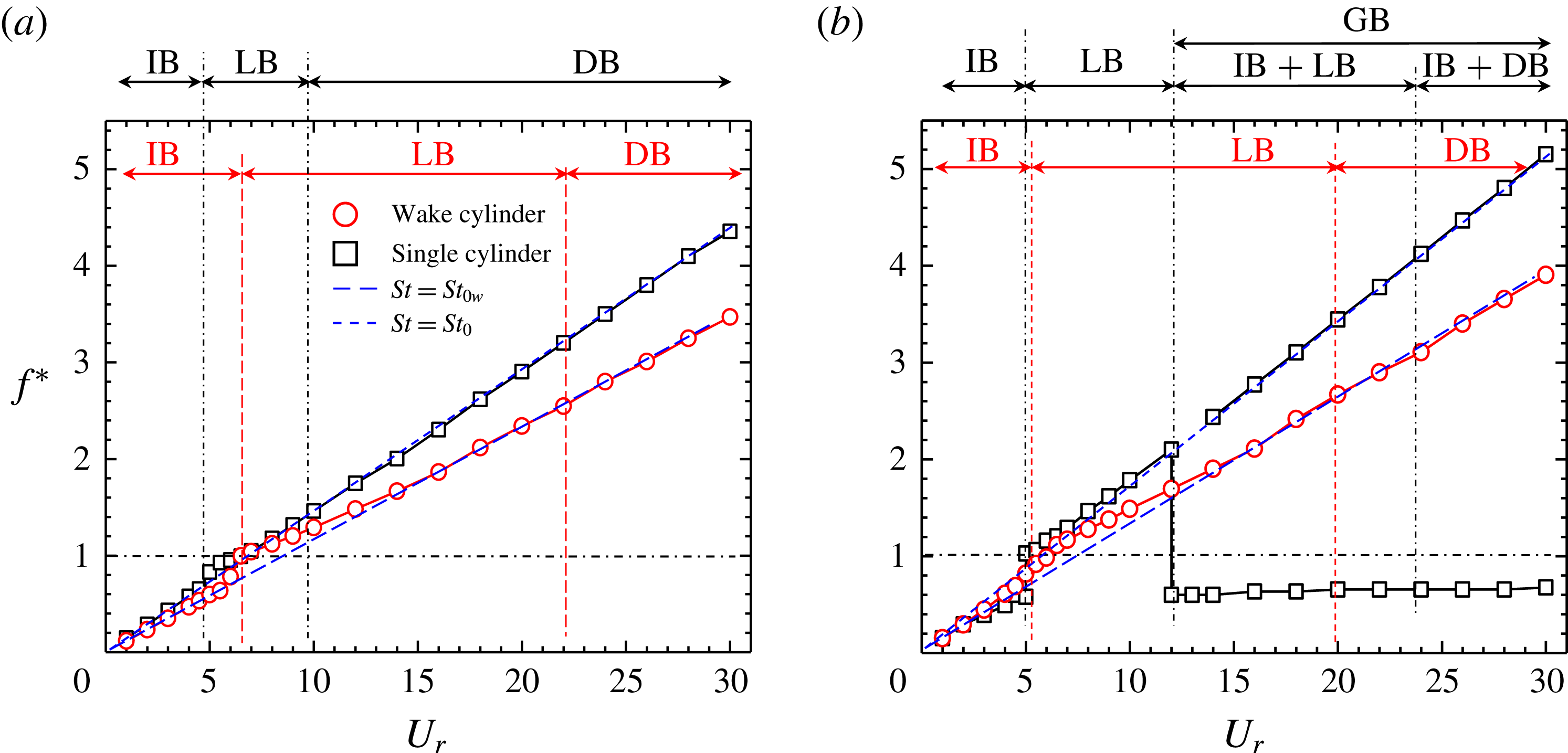
Figure 11. Variation in the oscillation frequency ratio
 $f^{\ast }\;(=\,f_{0}/f_{n})$
with the reduced velocity
$f^{\ast }\;(=\,f_{0}/f_{n})$
with the reduced velocity
 $U_{r}$
at (a)
$U_{r}$
at (a)
 $Re=100$
and (b)
$Re=100$
and (b)
 $Re=200$
. Here,
$Re=200$
. Here,
 $St_{0}$
and
$St_{0}$
and
 $St_{0w}$
represent the Strouhal numbers of the fixed single and wake cylinders respectively and
$St_{0w}$
represent the Strouhal numbers of the fixed single and wake cylinders respectively and
 $L^{\ast }=2$
.
$L^{\ast }=2$
.
A significant change takes place when
 $Re$
is increased to 200 (figure 11
b). For the single cylinder at
$Re$
is increased to 200 (figure 11
b). For the single cylinder at
 $U_{r}=5$
, there are two
$U_{r}=5$
, there are two
 $f^{\ast }$
values,
$f^{\ast }$
values,
 $f^{\ast }=0.58$
and 1.01, corresponding to the IB (2S) and LB (C(2S)) modes respectively. For
$f^{\ast }=0.58$
and 1.01, corresponding to the IB (2S) and LB (C(2S)) modes respectively. For
 $5<U_{r}\leqslant 12$
, a single value of
$5<U_{r}\leqslant 12$
, a single value of
 $f^{\ast }$
is seen, where the oscillation and shedding frequencies are the same. On the other hand, there are two values of
$f^{\ast }$
is seen, where the oscillation and shedding frequencies are the same. On the other hand, there are two values of
 $f^{\ast }$
for
$f^{\ast }$
for
 $U_{r}>12$
(GB) where the cylinder oscillation has two frequencies (figure 6
e), corresponding to the shedding frequency (close to the
$U_{r}>12$
(GB) where the cylinder oscillation has two frequencies (figure 6
e), corresponding to the shedding frequency (close to the
 $St=St_{0}$
line) and a modified natural frequency (
$St=St_{0}$
line) and a modified natural frequency (
 $f^{\ast }<1.0$
). The value of
$f^{\ast }<1.0$
). The value of
 $f^{\ast }({<}1.0)$
increases very slightly from 0.60 to 0.67 in the range
$f^{\ast }({<}1.0)$
increases very slightly from 0.60 to 0.67 in the range
 $U_{r}=12{-}30$
examined. The vibration amplitude at the shedding frequency is much smaller compared with that at
$U_{r}=12{-}30$
examined. The vibration amplitude at the shedding frequency is much smaller compared with that at
 $f^{\ast }<1.0$
(figure 6
e). The set of
$f^{\ast }<1.0$
(figure 6
e). The set of
 $f^{\ast }<1.0$
is predominant, at which the cylinder vibrates predominantly. This justifies the presence of the LB and the DB in the GB. For the wake cylinder, the high-frequency
$f^{\ast }<1.0$
is predominant, at which the cylinder vibrates predominantly. This justifies the presence of the LB and the DB in the GB. For the wake cylinder, the high-frequency
 $f^{\ast }$
–
$f^{\ast }$
–
 $U_{r}$
relationship differs from
$U_{r}$
relationship differs from
 $St=St_{0w}$
in the IB and the LB, but coincides in the DB.
$St=St_{0w}$
in the IB and the LB, but coincides in the DB.
5.1.4 Fluctuating lift force
Figure 12(a) shows
 $C_{L}^{\prime }$
for both the single and the wake cylinders at
$C_{L}^{\prime }$
for both the single and the wake cylinders at
 $Re=100$
. The
$Re=100$
. The
 $C_{L}^{\prime }$
of the single cylinder in the IB rises exponentially with
$C_{L}^{\prime }$
of the single cylinder in the IB rises exponentially with
 $U_{r}$
, attaining a peak at
$U_{r}$
, attaining a peak at
 $U_{r}=5$
where
$U_{r}=5$
where
 $A^{\ast }$
is maximum (figures 12
a, 4
a). The
$A^{\ast }$
is maximum (figures 12
a, 4
a). The
 $C_{L}^{\prime }$
in the LB plunges between
$C_{L}^{\prime }$
in the LB plunges between
 $U_{r}=5$
and 6.5 where
$U_{r}=5$
and 6.5 where
 $A^{\ast }$
rapidly decays. The plunge is attributed to
$A^{\ast }$
rapidly decays. The plunge is attributed to
 $f^{\ast }$
approaching 1.0 (figure 11
a). On the other hand,
$f^{\ast }$
approaching 1.0 (figure 11
a). On the other hand,
 $C_{L}^{\prime }$
grows slowly for
$C_{L}^{\prime }$
grows slowly for
 $U_{r}>6.5$
where the decay in
$U_{r}>6.5$
where the decay in
 $A^{\ast }$
occurs at a very small rate and
$A^{\ast }$
occurs at a very small rate and
 $f^{\ast }$
departs from
$f^{\ast }$
departs from
 $f^{\ast }=1.0$
. The change in
$f^{\ast }=1.0$
. The change in
 $C_{L}^{\prime }$
is relatively small in the DB regime. For the wake cylinder, the
$C_{L}^{\prime }$
is relatively small in the DB regime. For the wake cylinder, the
 $C_{L}^{\prime }$
is more or less constant in the IB (following
$C_{L}^{\prime }$
is more or less constant in the IB (following
 $A^{\ast }$
in figure 8
a), while it increases rapidly from
$A^{\ast }$
in figure 8
a), while it increases rapidly from
 $U_{r}=6.5$
to 12 in the LB and decreases for
$U_{r}=6.5$
to 12 in the LB and decreases for
 $U_{r}>12$
. Again, a small drop in
$U_{r}>12$
. Again, a small drop in
 $C_{L}^{\prime }$
between
$C_{L}^{\prime }$
between
 $U_{r}=6.0$
and 6.5 is attributed to the
$U_{r}=6.0$
and 6.5 is attributed to the
 $f^{\ast }$
becoming 1.0 (figure 11
a). The
$f^{\ast }$
becoming 1.0 (figure 11
a). The
 $C_{L}^{\prime }$
variations of the single and wake cylinders are opposite to each other for
$C_{L}^{\prime }$
variations of the single and wake cylinders are opposite to each other for
 $U_{r}>10$
, although
$U_{r}>10$
, although
 $A^{\ast }$
for the two cases follows similar trends.
$A^{\ast }$
for the two cases follows similar trends.

Figure 12. Variation in the fluctuating (r.m.s.) lift coefficient
 $C_{L}^{\prime }$
with reduced velocity
$C_{L}^{\prime }$
with reduced velocity
 $U_{r}$
at (a)
$U_{r}$
at (a)
 $Re=100$
and (b)
$Re=100$
and (b)
 $Re=200$
. Here,
$Re=200$
. Here,
 $L^{\ast }=2$
.
$L^{\ast }=2$
.
The variation in
 $C_{L}^{\prime }$
in the IB and the LB at
$C_{L}^{\prime }$
in the IB and the LB at
 $Re=200$
(figure 12
b) is similar to that at
$Re=200$
(figure 12
b) is similar to that at
 $Re=100$
. For
$Re=100$
. For
 $U_{r}>12$
where galloping vibration occurs for the single cylinder, the
$U_{r}>12$
where galloping vibration occurs for the single cylinder, the
 $C_{L}^{\prime }$
of the single cylinder surpasses that of the wake cylinder. With increasing
$C_{L}^{\prime }$
of the single cylinder surpasses that of the wake cylinder. With increasing
 $U_{r}\;({>}20)$
, the wake cylinder
$U_{r}\;({>}20)$
, the wake cylinder
 $C_{L}^{\prime }$
approaches a constant value (
$C_{L}^{\prime }$
approaches a constant value (
 $C_{L}^{\prime }=0.16$
) that is 52 % smaller than that of the single cylinder
$C_{L}^{\prime }=0.16$
) that is 52 % smaller than that of the single cylinder
 $C_{L}^{\prime }$
(
$C_{L}^{\prime }$
(
 $=0.34$
).
$=0.34$
).
5.2 Coshedding regime (
$L^{\ast }=6.0$
)

5.2.1 Vibration and frequency responses
The dependence on
 $U_{r}$
of the wake cylinder
$U_{r}$
of the wake cylinder
 $A^{\ast }$
at
$A^{\ast }$
at
 $L^{\ast }=6.0$
is shown in figure 13 for
$L^{\ast }=6.0$
is shown in figure 13 for
 $Re=100$
and 200. The response regimes are marked only for the wake cylinder. The boundaries between different branches are identified based on
$Re=100$
and 200. The response regimes are marked only for the wake cylinder. The boundaries between different branches are identified based on
 $St$
,
$St$
,
 $f^{\ast }$
and the phase lag between
$f^{\ast }$
and the phase lag between
 $Y$
and
$Y$
and
 $C_{L}$
. All follow the same relationships between themselves and branches as stated for the single cylinder. At
$C_{L}$
. All follow the same relationships between themselves and branches as stated for the single cylinder. At
 $Re=100$
, the
$Re=100$
, the
 $A^{\ast }$
of the wake cylinder is much higher in all three branches compared with that of the single cylinder. Furthermore, the variation in
$A^{\ast }$
of the wake cylinder is much higher in all three branches compared with that of the single cylinder. Furthermore, the variation in
 $A^{\ast }$
is different from that at
$A^{\ast }$
is different from that at
 $L^{\ast }=2.0$
(figure 8). The
$L^{\ast }=2.0$
(figure 8). The
 $A^{\ast }$
increases exponentially with
$A^{\ast }$
increases exponentially with
 $U_{r}$
, reaching a peak (
$U_{r}$
, reaching a peak (
 $A^{\ast }=0.67$
) at
$A^{\ast }=0.67$
) at
 $U_{r}=5.5$
, the peak value being approximately two times greater than the single cylinder
$U_{r}=5.5$
, the peak value being approximately two times greater than the single cylinder
 $A^{\ast }$
at
$A^{\ast }$
at
 $U_{r}=5$
(figure 13
a). Another peak forms in the LB regime at
$U_{r}=5$
(figure 13
a). Another peak forms in the LB regime at
 $U_{r}=8$
. The enhancement in
$U_{r}=8$
. The enhancement in
 $A^{\ast }$
of the wake cylinder compared with the single cylinder can be ascribed to the interaction of the upstream-cylinder-generated gap vortices with the wake cylinder. The
$A^{\ast }$
of the wake cylinder compared with the single cylinder can be ascribed to the interaction of the upstream-cylinder-generated gap vortices with the wake cylinder. The
 $A^{\ast }$
in the DB is approximately 12 times that of the single cylinder and three times that of the wake cylinder at
$A^{\ast }$
in the DB is approximately 12 times that of the single cylinder and three times that of the wake cylinder at
 $L^{\ast }=2.0$
. The transition from the IB to the LB is accompanied by a shift in the phase lag from
$L^{\ast }=2.0$
. The transition from the IB to the LB is accompanied by a shift in the phase lag from
 $0^{\circ }$
to
$0^{\circ }$
to
 $180^{\circ }$
(to be shown later) and by a change in
$180^{\circ }$
(to be shown later) and by a change in
 $St$
from
$St$
from
 $St<St_{w}$
to
$St<St_{w}$
to
 $St>St_{w}$
(figure 14
a). On the other hand,
$St>St_{w}$
(figure 14
a). On the other hand,
 $St>St_{w}$
and
$St>St_{w}$
and
 $St=St_{w}$
distinguish the LB and DB at
$St=St_{w}$
distinguish the LB and DB at
 $U_{r}=20$
.
$U_{r}=20$
.

Figure 13. Variation in the amplitude
 $A^{\ast }$
with the reduced velocity
$A^{\ast }$
with the reduced velocity
 $U_{r}$
at (a)
$U_{r}$
at (a)
 $Re=100$
and (b)
$Re=100$
and (b)
 $Re=200$
. Here,
$Re=200$
. Here,
 $L^{\ast }=6$
.
$L^{\ast }=6$
.
At
 $Re=200$
(figure 13
b), the response amplitude is very similar to the single-cylinder case for
$Re=200$
(figure 13
b), the response amplitude is very similar to the single-cylinder case for
 $U_{r}<5.0$
(IB). The
$U_{r}<5.0$
(IB). The
 $A^{\ast }$
, increasing with
$A^{\ast }$
, increasing with
 $U_{r}$
, reaches a value of 1.25 at
$U_{r}$
, reaches a value of 1.25 at
 $U_{r}=6$
, followed by a sudden drop at
$U_{r}=6$
, followed by a sudden drop at
 $U_{r}=6.5$
. As will be shown later,
$U_{r}=6.5$
. As will be shown later,
 $5.0<U_{r}<6.5$
represents the upper branch (UB) which is followed by the LB (
$5.0<U_{r}<6.5$
represents the upper branch (UB) which is followed by the LB (
 $6.5<U_{r}<14$
) and then the DB (
$6.5<U_{r}<14$
) and then the DB (
 $U_{r}>14$
). The phase lag between
$U_{r}>14$
). The phase lag between
 $C_{L}$
and
$C_{L}$
and
 $Y$
is approximately
$Y$
is approximately
 $0^{\circ }$
in the IB and the UB, and suddenly switches to
$0^{\circ }$
in the IB and the UB, and suddenly switches to
 $180^{\circ }$
in the LB. At
$180^{\circ }$
in the LB. At
 $Re=200$
, the UB and IB have the same characteristics in terms of the phase lag between
$Re=200$
, the UB and IB have the same characteristics in terms of the phase lag between
 $C_{L}$
and
$C_{L}$
and
 $Y$
and of the relationship between
$Y$
and of the relationship between
 $St$
and
$St$
and
 $St_{w}$
(figure 14
b). The vortex shedding mode, however, changes from a 2S at the IB to a
$St_{w}$
(figure 14
b). The vortex shedding mode, however, changes from a 2S at the IB to a
 $(\text{P}+\text{S})$
-like vortex arrangement at the UB, which will be shown later in § 5.4. Interestingly, no galloping vibration is observed for the wake cylinder at this
$(\text{P}+\text{S})$
-like vortex arrangement at the UB, which will be shown later in § 5.4. Interestingly, no galloping vibration is observed for the wake cylinder at this
 $Re$
, although it is observed for the single cylinder at
$Re$
, although it is observed for the single cylinder at
 $U_{r}>12$
. It is quite different from a circular cylinder. A single circular cylinder generally does not experience galloping vibration, but a wake circular cylinder does (Kim et al.
Reference Kim, Alam, Sakamoto and Zhou2009; Assi, Bearman & Meneghini Reference Assi, Bearman and Meneghini2010; Alam & Meyer Reference Alam and Meyer2013; Qin et al.
Reference Qin, Alam and Zhou2017). The opposite is true for square cylinders: galloping occurs for the single cylinder but not for the wake cylinder for the values of
$U_{r}>12$
. It is quite different from a circular cylinder. A single circular cylinder generally does not experience galloping vibration, but a wake circular cylinder does (Kim et al.
Reference Kim, Alam, Sakamoto and Zhou2009; Assi, Bearman & Meneghini Reference Assi, Bearman and Meneghini2010; Alam & Meyer Reference Alam and Meyer2013; Qin et al.
Reference Qin, Alam and Zhou2017). The opposite is true for square cylinders: galloping occurs for the single cylinder but not for the wake cylinder for the values of
 $L^{\ast }$
examined. It is expected that, for a sufficiently large value of
$L^{\ast }$
examined. It is expected that, for a sufficiently large value of
 $L^{\ast }$
, the wake cylinder will behave like an isolated cylinder, and galloping may come into being for the wake cylinder.
$L^{\ast }$
, the wake cylinder will behave like an isolated cylinder, and galloping may come into being for the wake cylinder.

Figure 14. Variation in the oscillation frequency ratio
 $f^{\ast }(=f_{0}/f_{n})$
with the reduced velocity
$f^{\ast }(=f_{0}/f_{n})$
with the reduced velocity
 $U_{r}$
at (a)
$U_{r}$
at (a)
 $Re=100$
and (b)
$Re=100$
and (b)
 $Re=200$
. Here,
$Re=200$
. Here,
 $St_{0}$
and
$St_{0}$
and
 $St_{0w}$
represent the Strouhal numbers of the fixed single and wake cylinders respectively and
$St_{0w}$
represent the Strouhal numbers of the fixed single and wake cylinders respectively and
 $L^{\ast }=6$
.
$L^{\ast }=6$
.
Recently, VIV of cylinders has received more attention because of its use as a source of energy harvesting. Mehmood et al. (Reference Mehmood, Abdelkefi, Hajj, Nayfeh, Akhtar and Uhait2013), at
 $96\leqslant Re\leqslant 118$
, investigated the concept of harvesting energy from VIV of a circular cylinder by attaching a piezoelectric transducer. They reported that the load resistance influences the oscillation amplitude, lift coefficient and harvested power. An increase in the load resistance widens the synchronization regime. Maruai et al. (Reference Maruai, Ali, Ismail and Zaki2018) numerically examined the transverse vibration of a square cylinder at
$96\leqslant Re\leqslant 118$
, investigated the concept of harvesting energy from VIV of a circular cylinder by attaching a piezoelectric transducer. They reported that the load resistance influences the oscillation amplitude, lift coefficient and harvested power. An increase in the load resistance widens the synchronization regime. Maruai et al. (Reference Maruai, Ali, Ismail and Zaki2018) numerically examined the transverse vibration of a square cylinder at
 $Re=3.6{-}12.5\times 10^{3}$
for
$Re=3.6{-}12.5\times 10^{3}$
for
 $m^{\ast }\unicode[STIX]{x1D701}=2.48$
. They introduced a downstream flat plate in the wake of a cylinder with gap spacing ratios of 0.1–3 and observed a large-amplitude vibration at a gap ratio of 0.1 where the power harvested was maximum. Presently, it is observed that the vibration amplitude of the wake cylinder is mainly dominated by the interaction between the gap vortices and the wake cylinder. The gap vortex may play an essential role in the energy transfer from the fluid to the cylinder, sustaining the high-amplitude vibration at
$m^{\ast }\unicode[STIX]{x1D701}=2.48$
. They introduced a downstream flat plate in the wake of a cylinder with gap spacing ratios of 0.1–3 and observed a large-amplitude vibration at a gap ratio of 0.1 where the power harvested was maximum. Presently, it is observed that the vibration amplitude of the wake cylinder is mainly dominated by the interaction between the gap vortices and the wake cylinder. The gap vortex may play an essential role in the energy transfer from the fluid to the cylinder, sustaining the high-amplitude vibration at
 $L^{\ast }=6$
. The vibration amplitude at
$L^{\ast }=6$
. The vibration amplitude at
 $L^{\ast }=6$
is remarkably enhanced compared with the cases of
$L^{\ast }=6$
is remarkably enhanced compared with the cases of
 $L^{\ast }=2$
(figures 8 and 13) and a single cylinder (figure 13) except for
$L^{\ast }=2$
(figures 8 and 13) and a single cylinder (figure 13) except for
 $U_{r}>18$
at
$U_{r}>18$
at
 $Re=200$
(figure 13
b). Interestingly, the wake cylinder at
$Re=200$
(figure 13
b). Interestingly, the wake cylinder at
 $L^{\ast }=6$
can be of a source of energy harvesting where the flow velocity is low.
$L^{\ast }=6$
can be of a source of energy harvesting where the flow velocity is low.
5.2.2 Wake structure
In the previous section, quite a few interesting observations were made, for example the formation of two peaks in
 $A^{\ast }$
at
$A^{\ast }$
at
 $Re=100$
and the presence of an UB at
$Re=100$
and the presence of an UB at
 $Re=200$
. We can gain insight into these phenomena through vorticity structures, vortex shedding process and work done on the cylinder by the fluid.
$Re=200$
. We can gain insight into these phenomena through vorticity structures, vortex shedding process and work done on the cylinder by the fluid.
5.3 Wake structure at different branches of vibration at
$Re=100$

5.3.1 Wake structure and phase relationship between
$C_{L}$
and
$Y$


Figure 15 shows vorticity structures and time histories of
 $C_{L}$
and
$C_{L}$
and
 $Y$
at different values of
$Y$
at different values of
 $U_{r}$
. Each snapshot corresponds to the instant at which the wake cylinder is at the bottom position (
$U_{r}$
. Each snapshot corresponds to the instant at which the wake cylinder is at the bottom position (
 $Y=-Y_{max}$
). The wakes at
$Y=-Y_{max}$
). The wakes at
 $U_{r}=1.0$
and 4.0 feature the 2S mode while that at
$U_{r}=1.0$
and 4.0 feature the 2S mode while that at
 $U_{r}=5.5$
is characterized by the C(2S) mode where
$U_{r}=5.5$
is characterized by the C(2S) mode where
 $A^{\ast }$
is maximum in the IB. The gap vortices vigorously interact with and impinge on the wake cylinder. Both the
$A^{\ast }$
is maximum in the IB. The gap vortices vigorously interact with and impinge on the wake cylinder. Both the
 $C_{L}$
and
$C_{L}$
and
 $Y$
amplitudes grow with increasing
$Y$
amplitudes grow with increasing
 $U_{r}$
from 1.0 to 5.5. Between
$U_{r}$
from 1.0 to 5.5. Between
 $U_{r}=5.5$
and 6 where
$U_{r}=5.5$
and 6 where
 $A^{\ast }$
drops,
$A^{\ast }$
drops,
 $C_{L}$
declines, and the C(2S) wake transmutes to the 2S wake (figure 15
c,d). The impinging vortex A on the lower surface (figure 15
c) dictates the shedding and
$C_{L}$
declines, and the C(2S) wake transmutes to the 2S wake (figure 15
c,d). The impinging vortex A on the lower surface (figure 15
c) dictates the shedding and
 $C_{L}$
, and its timing leads to an increase in
$C_{L}$
, and its timing leads to an increase in
 $C_{L}$
at
$C_{L}$
at
 $U_{r}=1.0{-}5.5$
and a drop at
$U_{r}=1.0{-}5.5$
and a drop at
 $U_{r}=5.5{-}7.0$
. The upper gap vortex B gets closer to the upper leading edge with increasing
$U_{r}=5.5{-}7.0$
. The upper gap vortex B gets closer to the upper leading edge with increasing
 $U_{r}$
from 5.5 to 7.0, which is another reason why
$U_{r}$
from 5.5 to 7.0, which is another reason why
 $C_{L}$
is reduced. At
$C_{L}$
is reduced. At
 $U_{r}=7.0$
, the gap vortex B impinging on the leading edge enhances the growth of the shear layer on the upper surface under an impulse (see the zoomed-in view). The mechanics enhances the upward lift force; the vortex B impinging on the upper surface of the wake cylinder at
$U_{r}=7.0$
, the gap vortex B impinging on the leading edge enhances the growth of the shear layer on the upper surface under an impulse (see the zoomed-in view). The mechanics enhances the upward lift force; the vortex B impinging on the upper surface of the wake cylinder at
 $U_{r}=8$
makes the
$U_{r}=8$
makes the
 $C_{L}$
positive and the phase lag
$C_{L}$
positive and the phase lag
 $180^{\circ }$
between
$180^{\circ }$
between
 $C_{L}$
and
$C_{L}$
and
 $Y$
. One can see in the zoomed-in views that two small shear layers form very close to the upper and lower surfaces respectively (figure 15
f, zoomed-in view). They have a greater impact on
$Y$
. One can see in the zoomed-in views that two small shear layers form very close to the upper and lower surfaces respectively (figure 15
f, zoomed-in view). They have a greater impact on
 $C_{L}$
as they are close to the cylinder. The vortex B also impinges on the upper surface. Therefore, the shear layers and vortex impingement result in a modification in
$C_{L}$
as they are close to the cylinder. The vortex B also impinges on the upper surface. Therefore, the shear layers and vortex impingement result in a modification in
 $C_{L}$
. The shear-layer shedding and associated lift are connected to the motion of the cylinder, in phase and antiphase with
$C_{L}$
. The shear-layer shedding and associated lift are connected to the motion of the cylinder, in phase and antiphase with
 $Y$
in the IB and LB regimes respectively, while the impingement-induced lift is contingent on
$Y$
in the IB and LB regimes respectively, while the impingement-induced lift is contingent on
 $U_{r}$
, as can be confirmed from the
$U_{r}$
, as can be confirmed from the
 $C_{L}$
and
$C_{L}$
and
 $Y$
histories. The shear-layer-induced vortex and impingement vortex form a binary vortex behind the cylinder, which results in a 2S wake. One question may arise as to why
$Y$
histories. The shear-layer-induced vortex and impingement vortex form a binary vortex behind the cylinder, which results in a 2S wake. One question may arise as to why
 $A^{\ast }$
increases and
$A^{\ast }$
increases and
 $C_{L}$
decays with
$C_{L}$
decays with
 $U_{r}$
increasing from 5.5 to 8. The point is that there is a phase lag between the upper shear-layer growth and the impinging vortex B (figure 15
c–f). As such, vortex B leads the shear layer at
$U_{r}$
increasing from 5.5 to 8. The point is that there is a phase lag between the upper shear-layer growth and the impinging vortex B (figure 15
c–f). As such, vortex B leads the shear layer at
 $U_{r}=6$
, is in phase with the shear layer at
$U_{r}=6$
, is in phase with the shear layer at
 $U_{r}=8$
and lags the shear layer at
$U_{r}=8$
and lags the shear layer at
 $U_{r}=10$
. This explains why
$U_{r}=10$
. This explains why
 $A^{\ast }$
increases between
$A^{\ast }$
increases between
 $U_{r}=6$
and 8, but declines for
$U_{r}=6$
and 8, but declines for
 $U_{r}>8$
.
$U_{r}>8$
.

Figure 15. Instantaneous vorticity (
 $\unicode[STIX]{x1D714}_{z}^{\ast }$
) structures and time histories of the lift force
$\unicode[STIX]{x1D714}_{z}^{\ast }$
) structures and time histories of the lift force
 $C_{L}$
(black lines) and displacement
$C_{L}$
(black lines) and displacement
 $Y$
(red lines) at various values of
$Y$
(red lines) at various values of
 $U_{r}$
. The instant of the snapshots corresponds to
$U_{r}$
. The instant of the snapshots corresponds to
 $Y=-Y_{max}$
. Here,
$Y=-Y_{max}$
. Here,
 $L^{\ast }=6$
and
$L^{\ast }=6$
and
 $Re=100$
.
$Re=100$
.
5.3.2 Vortex shedding process and work done
Here, we will explain the vortex shedding process at
 $U_{r}=8$
where
$U_{r}=8$
where
 $A^{\ast }$
is maximum in the LB. Figure 16 presents the mechanism of the vortex shedding process in one oscillation period. The (i), (ii), (iii), etc., given at the upper-left corners of the snapshots, represent the timings marked at the top of the time histories of
$A^{\ast }$
is maximum in the LB. Figure 16 presents the mechanism of the vortex shedding process in one oscillation period. The (i), (ii), (iii), etc., given at the upper-left corners of the snapshots, represent the timings marked at the top of the time histories of
 $Y$
and
$Y$
and
 $C_{L}$
in figure 17(
$C_{L}$
in figure 17(
 $\mathit{a}_{1}$
). Obviously,
$\mathit{a}_{1}$
). Obviously,
 $C_{L}$
and
$C_{L}$
and
 $Y$
are almost antiphase (figure 17
$Y$
are almost antiphase (figure 17
 $\mathit{a}_{1}$
). At instant (i), the cylinder is at its bottom position. A negative-vorticity shear layer separating from the upper leading edge of the wake cylinder reattaches on the trailing edge, forming a separation bubble and generating a vortex C
$\mathit{a}_{1}$
). At instant (i), the cylinder is at its bottom position. A negative-vorticity shear layer separating from the upper leading edge of the wake cylinder reattaches on the trailing edge, forming a separation bubble and generating a vortex C
 $_{1}$
(figure 16(i)). The shear-layer separation, reattachment and bubble formation can be clearly viewed in figure 16(i). The gap vortex B
$_{1}$
(figure 16(i)). The shear-layer separation, reattachment and bubble formation can be clearly viewed in figure 16(i). The gap vortex B
 $_{1}$
lies on the upper side surface of the wake cylinder. While the separation bubble, causing a highly negative pressure on the upper surface, results in the upward directed lift maximum, the impinging B
$_{1}$
lies on the upper side surface of the wake cylinder. While the separation bubble, causing a highly negative pressure on the upper surface, results in the upward directed lift maximum, the impinging B
 $_{1}$
weakens the growth of the shear layer and reduces the lift, forming a kink (figure 17
$_{1}$
weakens the growth of the shear layer and reduces the lift, forming a kink (figure 17
 $\mathit{a}_{1}$
) in
$\mathit{a}_{1}$
) in
 $C_{L}$
around instant (i). When the cylinder moves upward (instants ii, iii), vortices B
$C_{L}$
around instant (i). When the cylinder moves upward (instants ii, iii), vortices B
 $_{1}$
and C
$_{1}$
and C
 $_{1}$
form a binary vortex B
$_{1}$
form a binary vortex B
 $_{1}$
 $+$
C
$+$
C
 $_{1}$
that gets saturated at instant (iii) and completes its shedding at instant (iv) where the lower shear layer forms a separation bubble. Vortex B
$_{1}$
that gets saturated at instant (iii) and completes its shedding at instant (iv) where the lower shear layer forms a separation bubble. Vortex B
 $_{2}$
impinges on the lower corner at instant (iii) and restricts the growth of the shear layer at instant (iv), forming another kink in
$_{2}$
impinges on the lower corner at instant (iii) and restricts the growth of the shear layer at instant (iv), forming another kink in
 $C_{L}$
(figure 17
$C_{L}$
(figure 17
 $\mathit{a}_{1}$
). Between instants (iv) and (vi), the cylinder moves downward and the binary vortex B
$\mathit{a}_{1}$
). Between instants (iv) and (vi), the cylinder moves downward and the binary vortex B
 $_{2}$
 $+$
C
$+$
C
 $_{2}$
forming from B
$_{2}$
forming from B
 $_{2}$
and C
$_{2}$
and C
 $_{2}$
completes its shedding (figure 16iv–vi). This observation confirms a 2S mode. It is thus clear that, in one period of the vortex shedding, two impinging vortices form two kinks in the
$_{2}$
completes its shedding (figure 16iv–vi). This observation confirms a 2S mode. It is thus clear that, in one period of the vortex shedding, two impinging vortices form two kinks in the
 $C_{L}$
history, having a frequency of twice the oscillation frequency.
$C_{L}$
history, having a frequency of twice the oscillation frequency.
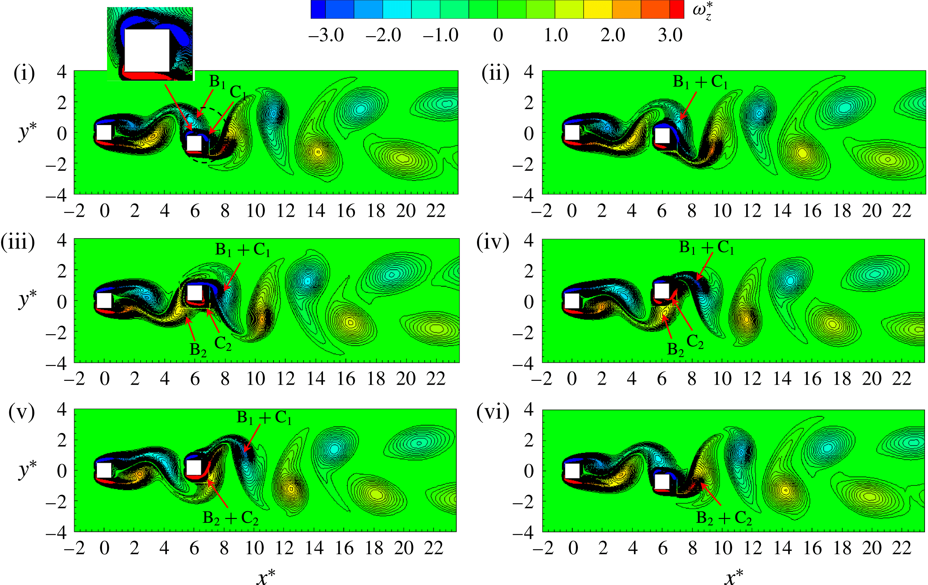
Figure 16. Instantaneous vorticity (
 $\unicode[STIX]{x1D714}_{z}^{\ast }$
) structures in one period of oscillation. The instants marked at the top left corners of the snapshots correspond to the timings marked at the top of figure 17(
$\unicode[STIX]{x1D714}_{z}^{\ast }$
) structures in one period of oscillation. The instants marked at the top left corners of the snapshots correspond to the timings marked at the top of figure 17(
 $\mathit{a}_{1}$
). Here,
$\mathit{a}_{1}$
). Here,
 $U_{r}=8$
,
$U_{r}=8$
,
 $L^{\ast }=6$
and
$L^{\ast }=6$
and
 $Re=100$
.
$Re=100$
.
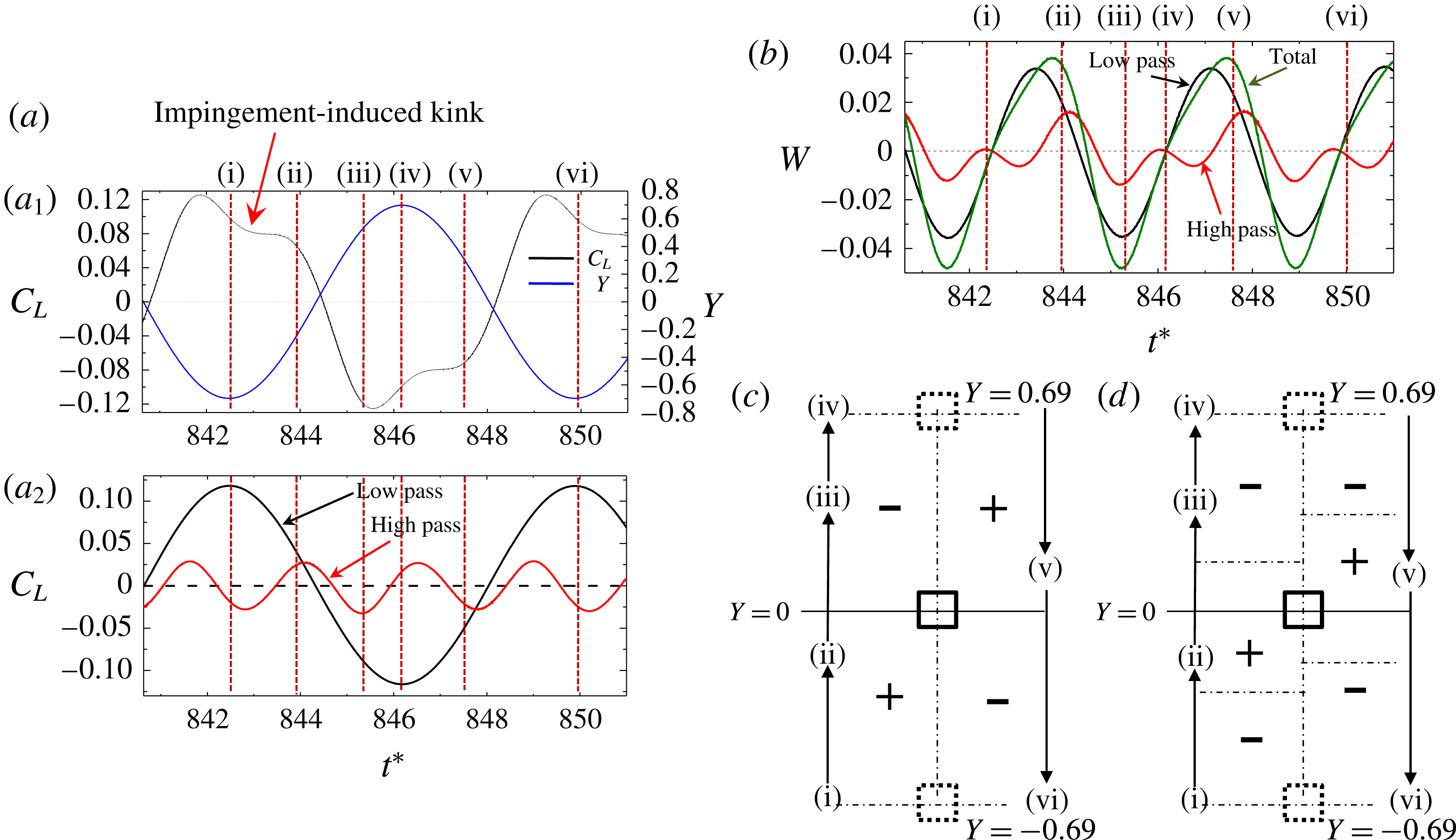
Figure 17. (a) Time histories of
 $Y$
,
$Y$
,
 $C_{L}$
and filtered
$C_{L}$
and filtered
 $C_{L}$
. (b) Temporal variation of total work done and filtered work done. (c,d) Sketch for the signs of the work done by vortex shedding and vortex impingement respectively in one cycle of the cylinder oscillation. The instants marked at the top of figure 17(
$C_{L}$
. (b) Temporal variation of total work done and filtered work done. (c,d) Sketch for the signs of the work done by vortex shedding and vortex impingement respectively in one cycle of the cylinder oscillation. The instants marked at the top of figure 17(
 $\mathit{a}_{1}$
) correspond to the snapshots in figure 16. Here,
$\mathit{a}_{1}$
) correspond to the snapshots in figure 16. Here,
 $U_{r}=8$
,
$U_{r}=8$
,
 $L^{\ast }=6$
and
$L^{\ast }=6$
and
 $Re=100$
.
$Re=100$
.
The vortex shedding from the upper and lower sides of the cylinder (figure 16(i,iv)) leads to a variation in
 $C_{L}$
following the vortex shedding frequency. On the other hand, the gap-vortex impingement occurs twice in one vortex shedding cycle, leading to a variation in
$C_{L}$
following the vortex shedding frequency. On the other hand, the gap-vortex impingement occurs twice in one vortex shedding cycle, leading to a variation in
 $C_{L}$
at a frequency of twice the shedding frequency. The
$C_{L}$
at a frequency of twice the shedding frequency. The
 $C_{L}$
thus constitutes a low frequency (shedding frequency) and a high frequency (impinging frequency), the former being the same as the oscillation frequency. In order to see the
$C_{L}$
thus constitutes a low frequency (shedding frequency) and a high frequency (impinging frequency), the former being the same as the oscillation frequency. In order to see the
 $C_{L}$
amplitude corresponding to the cylinder-oscillation frequency and vortex impingement frequency, low- and high-pass-filtered
$C_{L}$
amplitude corresponding to the cylinder-oscillation frequency and vortex impingement frequency, low- and high-pass-filtered
 $C_{L}$
histories are presented in figure 17(
$C_{L}$
histories are presented in figure 17(
 $\mathit{a}_{2}$
). The cutoff frequency was 1.5 times the cylinder-oscillation frequency. Obviously, the
$\mathit{a}_{2}$
). The cutoff frequency was 1.5 times the cylinder-oscillation frequency. Obviously, the
 $C_{L}$
amplitude induced by the impingement is smaller than that by the vortex shedding from the cylinder. The vortex-shedding-induced
$C_{L}$
amplitude induced by the impingement is smaller than that by the vortex shedding from the cylinder. The vortex-shedding-induced
 $C_{L}$
is positive and negative (instants (i, iv), figure 17
$C_{L}$
is positive and negative (instants (i, iv), figure 17
 $\mathit{a}_{2}$
) when the vortex shedding occurs from the upper and lower sides respectively (figure 16(i,iv)). Interestingly, when the gap vortex B
$\mathit{a}_{2}$
) when the vortex shedding occurs from the upper and lower sides respectively (figure 16(i,iv)). Interestingly, when the gap vortex B
 $_{1}$
impinges near the leading edge of the cylinder (figure 16(i)), the associated
$_{1}$
impinges near the leading edge of the cylinder (figure 16(i)), the associated
 $C_{L}$
(i.e. high pass) is negative (figure 17
$C_{L}$
(i.e. high pass) is negative (figure 17
 $\mathit{a}_{2}$
). As it passes over the trailing edge (figure 16(ii)), the associated
$\mathit{a}_{2}$
). As it passes over the trailing edge (figure 16(ii)), the associated
 $C_{L}$
becomes positive (instant (ii) in figure 17
$C_{L}$
becomes positive (instant (ii) in figure 17
 $\mathit{a}_{2}$
). The
$\mathit{a}_{2}$
). The
 $C_{L}$
associated with the shedding is antiphase with
$C_{L}$
associated with the shedding is antiphase with
 $Y$
while that associated with the impingement is almost in phase with
$Y$
while that associated with the impingement is almost in phase with
 $Y$
, considering the peak-to-peak phase. The latter is thus responsible for the large
$Y$
, considering the peak-to-peak phase. The latter is thus responsible for the large
 $A^{\ast }$
.
$A^{\ast }$
.
It is worth seeing the work done by the vortex shedding and impingement. Figure 17(b) shows time histories of work done
 $W$
$W$
 $(=C_{L}\,\text{d}Y)$
by the vortex-shedding-induced
$(=C_{L}\,\text{d}Y)$
by the vortex-shedding-induced
 $C_{L}$
(low pass), impingement-induced
$C_{L}$
(low pass), impingement-induced
 $C_{L}$
(high pass) and the total
$C_{L}$
(high pass) and the total
 $C_{L}$
. The work done fluctuates from positive to negative and vice versa for all three cases. This means that the cylinder gains energy from the flow when the work done is positive, and, in the opposite case, the cylinder releases energy to the flow when the work done is negative. Apparently, the transfer of energy between the cylinder and the flow predominantly occurs due to the shedding (low pass), following the total work done. The shedding-induced work done is positive when the cylinder moves from the bottom (instant (i)) to the mid (
$C_{L}$
. The work done fluctuates from positive to negative and vice versa for all three cases. This means that the cylinder gains energy from the flow when the work done is positive, and, in the opposite case, the cylinder releases energy to the flow when the work done is negative. Apparently, the transfer of energy between the cylinder and the flow predominantly occurs due to the shedding (low pass), following the total work done. The shedding-induced work done is positive when the cylinder moves from the bottom (instant (i)) to the mid (
 $Y=0$
) position (figure 17
c), where
$Y=0$
) position (figure 17
c), where
 $C_{L}$
is induced by the growth of the shear layer on the upper side (figure 16(i,ii)). On the other hand, the work is negative when the cylinder departing from the midposition reaches the top position, where the shear layer completes its vortex shedding (figure 16(iii,iv)). The same happens when the cylinder moves from the top to the bottom (figure 17
c). The impingement-induced work done, however, behaves differently (figure 17
b,d). As the cylinder moves up from the bottom, the impingement of the vortex on the side surface (figure 16(i)) produces negative work done first (figure 17
b,d). When near the trailing edge (figure 16(ii)), the impinging vortex renders positive work done, the cylinder lying close to the midposition (figure 17
d). Its shedding (figure 16(iii,iv) causes again negative work done (figure 17
b,d) where the cylinder is away from the midposition. In other words, the work done is positive when the cylinder is around the midposition and negative when the cylinder is near the top or bottom position. Indeed, the positive work done around
$C_{L}$
is induced by the growth of the shear layer on the upper side (figure 16(i,ii)). On the other hand, the work is negative when the cylinder departing from the midposition reaches the top position, where the shear layer completes its vortex shedding (figure 16(iii,iv)). The same happens when the cylinder moves from the top to the bottom (figure 17
c). The impingement-induced work done, however, behaves differently (figure 17
b,d). As the cylinder moves up from the bottom, the impingement of the vortex on the side surface (figure 16(i)) produces negative work done first (figure 17
b,d). When near the trailing edge (figure 16(ii)), the impinging vortex renders positive work done, the cylinder lying close to the midposition (figure 17
d). Its shedding (figure 16(iii,iv) causes again negative work done (figure 17
b,d) where the cylinder is away from the midposition. In other words, the work done is positive when the cylinder is around the midposition and negative when the cylinder is near the top or bottom position. Indeed, the positive work done around
 $Y=0$
is useful to enhance the vibration amplitude.
$Y=0$
is useful to enhance the vibration amplitude.
Figure 18 shows the instantaneous vorticity contours for
 $U_{r}=6$
in one vibration period. The influence of the gap vortices on the wake vortex formation is very similar to that in figure 16 for
$U_{r}=6$
in one vibration period. The influence of the gap vortices on the wake vortex formation is very similar to that in figure 16 for
 $U_{r}=8$
in the LB. In each vibration period, two vortices are found to shed in the 2S mode. When the cylinder is at its bottom position, the gap vortex approaches the leading edge of the cylinder (figure 18
b (i,vi)) while it impinges on the upper surface for
$U_{r}=8$
in the LB. In each vibration period, two vortices are found to shed in the 2S mode. When the cylinder is at its bottom position, the gap vortex approaches the leading edge of the cylinder (figure 18
b (i,vi)) while it impinges on the upper surface for
 $U_{r}=8$
(figure 16(i,vi)). Here, the low- and high-pass-filtered
$U_{r}=8$
(figure 16(i,vi)). Here, the low- and high-pass-filtered
 $C_{L}$
display that the
$C_{L}$
display that the
 $C_{L}$
induced by the shedding and impingement both are almost in phase with
$C_{L}$
induced by the shedding and impingement both are almost in phase with
 $Y$
(not shown).
$Y$
(not shown).

Figure 18. (a) Time histories of
 $Y$
and
$Y$
and
 $C_{L}$
. (b) Instantaneous vorticity (
$C_{L}$
. (b) Instantaneous vorticity (
 $\unicode[STIX]{x1D714}_{z}^{\ast }$
) contours at the timings marked at the top of (a). Here,
$\unicode[STIX]{x1D714}_{z}^{\ast }$
) contours at the timings marked at the top of (a). Here,
 $U_{r}=6$
,
$U_{r}=6$
,
 $L^{\ast }=6$
and
$L^{\ast }=6$
and
 $Re=100$
.
$Re=100$
.
5.4 Wake structure at different branches of vibration at
$Re=200$

The dependence of the wake structure on
 $U_{r}$
at
$U_{r}$
at
 $Re=200$
is shown in figure 19. The wake is characterized by the 2S mode at
$Re=200$
is shown in figure 19. The wake is characterized by the 2S mode at
 $U_{r}=1$
, the C(2S) mode at
$U_{r}=1$
, the C(2S) mode at
 $U_{r}=4$
, the
$U_{r}=4$
, the
 $\text{P}+\text{S}$
mode at
$\text{P}+\text{S}$
mode at
 $U_{r}=5{-}6$
and the 2S mode for
$U_{r}=5{-}6$
and the 2S mode for
 $U_{r}>6$
. The presence of the
$U_{r}>6$
. The presence of the
 $\text{P}+\text{S}$
mode at
$\text{P}+\text{S}$
mode at
 $U_{r}=5{-}6$
confirms the UB. The phase of vortex shedding from the wake cylinder does not change for
$U_{r}=5{-}6$
confirms the UB. The phase of vortex shedding from the wake cylinder does not change for
 $U_{r}\leqslant 6$
(IB and UB), but changes from
$U_{r}\leqslant 6$
(IB and UB), but changes from
 $0^{\circ }$
to
$0^{\circ }$
to
 $180^{\circ }$
between
$180^{\circ }$
between
 $U_{r}=6$
(UB) and 6.5 (LB) where
$U_{r}=6$
(UB) and 6.5 (LB) where
 $A^{\ast }$
is slashed. The wake features a 2S mode and a phase of lag
$A^{\ast }$
is slashed. The wake features a 2S mode and a phase of lag
 $180^{\circ }$
beyond
$180^{\circ }$
beyond
 $U_{r}\geqslant 6.5$
(figure 19
e,f).
$U_{r}\geqslant 6.5$
(figure 19
e,f).

Figure 19. Instantaneous vorticity (
 $\unicode[STIX]{x1D714}_{z}^{\ast }$
) contours of upstream stationary and downstream vibrating square cylinders at various values of
$\unicode[STIX]{x1D714}_{z}^{\ast }$
) contours of upstream stationary and downstream vibrating square cylinders at various values of
 $U_{r}$
,
$U_{r}$
,
 $L^{\ast }=6$
and
$L^{\ast }=6$
and
 $Re=200$
.
$Re=200$
.
Figure 20 illustrates the timing and process of vortex shedding at
 $U_{r}=6$
in one vibration period. The instants of the snapshots are marked in the time histories of
$U_{r}=6$
in one vibration period. The instants of the snapshots are marked in the time histories of
 $C_{L}$
and
$C_{L}$
and
 $Y$
in figure 20(a). Here,
$Y$
in figure 20(a). Here,
 $C_{L}$
and
$C_{L}$
and
 $Y$
are almost in phase, indicating that the shear layers and impinging vortices contribute to the lift at the same phase. The
$Y$
are almost in phase, indicating that the shear layers and impinging vortices contribute to the lift at the same phase. The
 $C_{L}$
amplitude is thus enhanced, leading to a high
$C_{L}$
amplitude is thus enhanced, leading to a high
 $A^{\ast }$
at this
$A^{\ast }$
at this
 $U_{r}$
.
$U_{r}$
.

Figure 20. (a) Time histories of
 $Y$
and
$Y$
and
 $C_{L}$
. (b) Instantaneous vorticity (
$C_{L}$
. (b) Instantaneous vorticity (
 $\unicode[STIX]{x1D714}_{z}^{\ast }$
) contours at the timings marked at the top of (a). Here,
$\unicode[STIX]{x1D714}_{z}^{\ast }$
) contours at the timings marked at the top of (a). Here,
 $U_{r}=6$
,
$U_{r}=6$
,
 $L^{\ast }=6$
and
$L^{\ast }=6$
and
 $Re=200$
.
$Re=200$
.
At instant (i), the cylinder is at its top position, and vortices A–E lie around the wake cylinder. As the cylinder moves downward from instants (i)–(iv), vortex D sheds from the upper side of the cylinder and vortex E grows on the lower side, leading to a decrease in
 $C_{L}$
(figure 20
a). Similarly, vortex E sheds from the lower side and another vortex F grows on the upper side when the cylinder moves from the bottom to the top (instants (iv–vi)). The
$C_{L}$
(figure 20
a). Similarly, vortex E sheds from the lower side and another vortex F grows on the upper side when the cylinder moves from the bottom to the top (instants (iv–vi)). The
 $C_{L}$
thus increases in this half-period. In one cylinder-oscillation period, two vortices D and E shed from the two sides respectively. It is clear from figure 20(b) that the flow around the cylinder at instant (iv) is the mirror image of the flow at instant (i). The alternating vortex shedding thus occurs in the 2S mode, which leads to almost zero mean lift (
$C_{L}$
thus increases in this half-period. In one cylinder-oscillation period, two vortices D and E shed from the two sides respectively. It is clear from figure 20(b) that the flow around the cylinder at instant (iv) is the mirror image of the flow at instant (i). The alternating vortex shedding thus occurs in the 2S mode, which leads to almost zero mean lift (
 $\bar{C}_{L}=-0.0022$
) and zero mean displacement (
$\bar{C}_{L}=-0.0022$
) and zero mean displacement (
 $\overline{Y}=-0.0021$
). However, the vortices shedding in the 2S mode arrange in a (
$\overline{Y}=-0.0021$
). However, the vortices shedding in the 2S mode arrange in a (
 $\text{P}+\text{S}$
)-like mode in the wake as they evolve downstream, as marked on the snapshot at instant (vi). Since the arrangement of vortices in the (
$\text{P}+\text{S}$
)-like mode in the wake as they evolve downstream, as marked on the snapshot at instant (vi). Since the arrangement of vortices in the (
 $\text{P}+\text{S}$
)-like mode occurs downstream (
$\text{P}+\text{S}$
)-like mode occurs downstream (
 $x^{\ast }>14$
), it has an insignificant impact on
$x^{\ast }>14$
), it has an insignificant impact on
 $\bar{C}_{L}$
and
$\bar{C}_{L}$
and
 $\overline{Y}$
.
$\overline{Y}$
.
6 Discussion
Table 3 outlines the major features of the vibration responses at different values of
 $Re$
and
$Re$
and
 $L^{\ast }$
. The IB and LB appear for all of the cases, while the UB and GB materialize for the wake cylinder (
$L^{\ast }$
. The IB and LB appear for all of the cases, while the UB and GB materialize for the wake cylinder (
 $L^{\ast }=6.0$
) and single cylinder respectively, both at
$L^{\ast }=6.0$
) and single cylinder respectively, both at
 $Re=200$
. The DB is absent for the single cylinder at
$Re=200$
. The DB is absent for the single cylinder at
 $Re=200$
. The IB, LB and DB are all delayed for the wake cylinder compared with the single cylinder. While the LB for
$Re=200$
. The IB, LB and DB are all delayed for the wake cylinder compared with the single cylinder. While the LB for
 $L^{\ast }=2.0$
is much wider than that for the single cylinder regardless of
$L^{\ast }=2.0$
is much wider than that for the single cylinder regardless of
 $Re$
, that for
$Re$
, that for
 $L^{\ast }=6.0$
is less wide. Both the LB and the DB are characterized by
$L^{\ast }=6.0$
is less wide. Both the LB and the DB are characterized by
 $A^{\ast }$
decreasing with
$A^{\ast }$
decreasing with
 $U_{r}$
. While in the literature the initial branch is known as the
$U_{r}$
. While in the literature the initial branch is known as the
 $A^{\ast }$
increasing with
$A^{\ast }$
increasing with
 $U_{r}$
, this is not the case for the wake cylinder at
$U_{r}$
, this is not the case for the wake cylinder at
 $L^{\ast }=6.0$
,
$L^{\ast }=6.0$
,
 $Re=100$
, where
$Re=100$
, where
 $A^{\ast }$
first grows with
$A^{\ast }$
first grows with
 $U_{r}$
, followed by a decline and then another augmentation.
$U_{r}$
, followed by a decline and then another augmentation.
In the reattachment regime (
 $L^{\ast }=2$
), the vibration amplitude response of the wake cylinder has a similar trend to that of the single cylinder (figure 8
a). The magnitude of
$L^{\ast }=2$
), the vibration amplitude response of the wake cylinder has a similar trend to that of the single cylinder (figure 8
a). The magnitude of
 $A^{\ast }$
for the wake cylinder is, however, smaller in the IB and larger in the LB and the DB compared with its single-cylinder counterpart. The complexity of the response of the wake cylinder significantly increases at
$A^{\ast }$
for the wake cylinder is, however, smaller in the IB and larger in the LB and the DB compared with its single-cylinder counterpart. The complexity of the response of the wake cylinder significantly increases at
 $L^{\ast }=6$
(figure 13). Both gap-vortex impingement and wake-cylinder shedding play a role in the vibration response. Because of the impingement, the
$L^{\ast }=6$
(figure 13). Both gap-vortex impingement and wake-cylinder shedding play a role in the vibration response. Because of the impingement, the
 $A^{\ast }$
of the wake cylinder is greater than that of the single cylinder for all of the regimes, except in the GB. The UB appearing for the wake cylinder at
$A^{\ast }$
of the wake cylinder is greater than that of the single cylinder for all of the regimes, except in the GB. The UB appearing for the wake cylinder at
 $L^{\ast }=6$
,
$L^{\ast }=6$
,
 $Re=200$
is characterized by
$Re=200$
is characterized by
 $A^{\ast }$
as high as 1.2, approximately three times the maximum
$A^{\ast }$
as high as 1.2, approximately three times the maximum
 $A^{\ast }$
of the single cylinder.
$A^{\ast }$
of the single cylinder.
Table 3. Major features of the vibration response at different values of
 $Re$
and
$Re$
and
 $L^{\ast }$
.
$L^{\ast }$
.

7 Conclusions
A numerical study at
 $Re=100$
and 200 has been conducted on the flow-induced vibration of a square cylinder placed in the wake of an identical cylinder at spacing ratios of
$Re=100$
and 200 has been conducted on the flow-induced vibration of a square cylinder placed in the wake of an identical cylinder at spacing ratios of
 $L^{\ast }=2$
and 6, corresponding to the reattachment and coshedding flow regimes. A single cylinder was examined first to gain insight into the vibration response and corresponding flow physics. The reduced velocity
$L^{\ast }=2$
and 6, corresponding to the reattachment and coshedding flow regimes. A single cylinder was examined first to gain insight into the vibration response and corresponding flow physics. The reduced velocity
 $U_{r}$
was varied from 1 to 30. The vibration responses, frequency responses, vortex structures and work done on the cylinder were presented and connected to the vortex shedding process. The investigation led to the following conclusions.
$U_{r}$
was varied from 1 to 30. The vibration responses, frequency responses, vortex structures and work done on the cylinder were presented and connected to the vortex shedding process. The investigation led to the following conclusions.
The single isolated cylinder experiences the IB, the LB and the DB at
 $Re=100$
. On the other hand, at
$Re=100$
. On the other hand, at
 $Re=200$
, the cylinder undergoes the IB, the LB and the GB. The vibration amplitude in the GB increases with
$Re=200$
, the cylinder undergoes the IB, the LB and the GB. The vibration amplitude in the GB increases with
 $U_{r}\;({>}12)$
. Insight into the vibration response in the GB is imparted. At the initial stage (
$U_{r}\;({>}12)$
. Insight into the vibration response in the GB is imparted. At the initial stage (
 $12<U_{r}<24$
) of the GB where the vibration amplitude rapidly grows with
$12<U_{r}<24$
) of the GB where the vibration amplitude rapidly grows with
 $U_{r}$
, the galloping vibration bears combined features of the IB and the LB. The vibration amplitude is predominantly contributed by the flow features associated with the IB. On the other hand, at the late stage (
$U_{r}$
, the galloping vibration bears combined features of the IB and the LB. The vibration amplitude is predominantly contributed by the flow features associated with the IB. On the other hand, at the late stage (
 $U_{r}>24$
) of the GB where the growth of the vibration amplitude is small, a combination of features associated with the IB and the DB prevails. Different branches can be distinguished based on the
$U_{r}>24$
) of the GB where the growth of the vibration amplitude is small, a combination of features associated with the IB and the DB prevails. Different branches can be distinguished based on the
 $St{-}St_{0}$
relationship. The IB, LB and DB follow
$St{-}St_{0}$
relationship. The IB, LB and DB follow
 $St<St_{0}$
,
$St<St_{0}$
,
 $St>St_{0}$
and
$St>St_{0}$
and
 $St\approx St_{0}$
relationships respectively. In the IB, both the
$St\approx St_{0}$
relationships respectively. In the IB, both the
 $C_{L}$
and
$C_{L}$
and
 $Y$
histories undergo a beat where the amplitudes of
$Y$
histories undergo a beat where the amplitudes of
 $C_{L}$
and
$C_{L}$
and
 $Y$
are not constant, but become large and small alternately. The beat results from a change in the sign of the phase lag between
$Y$
are not constant, but become large and small alternately. The beat results from a change in the sign of the phase lag between
 $C_{L}$
and
$C_{L}$
and
 $Y$
. A large amplitude corresponds to
$Y$
. A large amplitude corresponds to
 $C_{L}$
leading
$C_{L}$
leading
 $Y$
, which provides positive work done on the cylinder. On the other hand, a small amplitude stems from
$Y$
, which provides positive work done on the cylinder. On the other hand, a small amplitude stems from
 $C_{L}$
lagging
$C_{L}$
lagging
 $Y$
, the cylinder releasing energy to the flow (negative work).
$Y$
, the cylinder releasing energy to the flow (negative work).
When the cylinder is placed in the wake of another cylinder with a separation (
 $L^{\ast }=2$
) corresponding to the reattachment flow regime, the IB is delayed and the LB is elongated for either
$L^{\ast }=2$
) corresponding to the reattachment flow regime, the IB is delayed and the LB is elongated for either
 $Re$
. The vibration amplitudes in the IB and the LB are smaller and higher respectively for the wake cylinder than for the isolated cylinder. In the IB, a quasisteady reattachment of the upstream-cylinder-generated shear layers occurs on the wake cylinder, which results in a smaller amplitude for the wake cylinder than the isolated cylinder. The reattachment of the shear layers becomes alternating in the LB regime, causing the amplitude to be higher for the wake cylinder. The galloping vibration appearing for the isolated cylinder at
$Re$
. The vibration amplitudes in the IB and the LB are smaller and higher respectively for the wake cylinder than for the isolated cylinder. In the IB, a quasisteady reattachment of the upstream-cylinder-generated shear layers occurs on the wake cylinder, which results in a smaller amplitude for the wake cylinder than the isolated cylinder. The reattachment of the shear layers becomes alternating in the LB regime, causing the amplitude to be higher for the wake cylinder. The galloping vibration appearing for the isolated cylinder at
 $Re=200$
is absent for the wake cylinder.
$Re=200$
is absent for the wake cylinder.
The vibration response of the wake cylinder at
 $L^{\ast }=6$
is different from that at
$L^{\ast }=6$
is different from that at
 $L^{\ast }=2.0$
. While the IB, LB and DB are identified at
$L^{\ast }=2.0$
. While the IB, LB and DB are identified at
 $Re=100$
, an UB emerges between the IB and the LB at
$Re=100$
, an UB emerges between the IB and the LB at
 $Re=200$
. Again, the GB is not observed at either
$Re=200$
. Again, the GB is not observed at either
 $Re$
. However, the vibration amplitude is greater than that of the single cylinder for all regimes, except for the GB. The enhancement in amplitude is attributed to the interaction of the gap vortices with the wake cylinder. The vibration amplitude in the IB of the single cylinder increases with increasing
$Re$
. However, the vibration amplitude is greater than that of the single cylinder for all regimes, except for the GB. The enhancement in amplitude is attributed to the interaction of the gap vortices with the wake cylinder. The vibration amplitude in the IB of the single cylinder increases with increasing
 $U_{r}$
, which is the general characteristic of the IB, known in the literature. For the wake cylinder at
$U_{r}$
, which is the general characteristic of the IB, known in the literature. For the wake cylinder at
 $Re=100$
, the vibration amplitude in the IB first increases with increasing
$Re=100$
, the vibration amplitude in the IB first increases with increasing
 $U_{r}$
up to
$U_{r}$
up to
 $U_{r}=5.5$
, drastically declines between
$U_{r}=5.5$
, drastically declines between
 $U_{r}=5.5$
and 6.0, and then increases again. This observed facet is different from that known in the literature for a single square or circular cylinder. The phase lag between the impinging vortex and the vortex shedding from the wake cylinder changes with increasing
$U_{r}=5.5$
and 6.0, and then increases again. This observed facet is different from that known in the literature for a single square or circular cylinder. The phase lag between the impinging vortex and the vortex shedding from the wake cylinder changes with increasing
 $U_{r}$
, which is ascribed to such variation in the vibration amplitude. In other words, the phase lag between the impingement-induced lift and the cylinder displacement dictates the growth and decay of the vibration amplitude in the IB. The vibration amplitude becomes maximum when the impingement-induced lift is in phase with the cylinder displacement, producing the positive work done around
$U_{r}$
, which is ascribed to such variation in the vibration amplitude. In other words, the phase lag between the impingement-induced lift and the cylinder displacement dictates the growth and decay of the vibration amplitude in the IB. The vibration amplitude becomes maximum when the impingement-induced lift is in phase with the cylinder displacement, producing the positive work done around
 $Y=0$
, which is useful to enhance the vibration amplitude.
$Y=0$
, which is useful to enhance the vibration amplitude.
Acknowledgement
Md.M.A. wishes to acknowledge the support given by the National Natural Science Foundation of China through grants 11672096 and 91752112 and by the Research Grant Council of the Shenzhen Government through grant JCYJ20170811152808282.


