


1. Introduction
In a fairly recent review article (Kim et al. Reference Kim, Boysen, Newhouse, Spatocco, Chung, Burke, Bradwell, Jiang, Tomaszowska, Wang, Wei, Ortiz, Barriga, Poizeau and Sadoway2013) on liquid metal batteries (LMBs), Professor D. Sadoway’s group at MIT proposed LMBs as a solution to meet future electrical energy storage problems. Although LMBs have been around for some time already, this proposal ignited a global interest for this technology; we refer to Weaver, Smith & Willmann (Reference Weaver, Smith and Willmann1962), Agruss (Reference Agruss1963), Cairns et al. (Reference Cairns, Crouthamel, Fischer, Foster, Hesson, Johnson, Shimotake and Tevebaugh1967), Crouthamel & Recht (Reference Crouthamel and Recht1967), Cairns & Shimotake (Reference Cairns and Shimotake1969), Swinkels (Reference Swinkels, Braunstein, Mamantov and Smith1971), Steunenberg & Burris (Reference Steunenberg and Burris2000) from Weber et al. (Reference Weber, Galindo, Stefani and Weier2014) for early works on LMBs. LMBs are usually composed of three layers of fluids (liquid metal electrode–electrolyte–liquid metal electrode) of different densities stacked over each other and stabilized by gravity. Apart from the liquid aspect, the electrical function of LMBs is identical to common galvanic cells. LMBs have several advantages with respect to classical galvanic cells when it comes to large-scale power generation though. Common galvanic cells are built using solid and liquid (or gel) components for the electrodes and the electrolytes, and the solid–liquid interfaces gradually degrade through charging and discharging, thereby limiting the cell’s lifetime and size. Galvanic batteries meeting powergrid standards could be built in principle by connecting large numbers of small cells, but this would be expensive to produce and maintain. The erosion problems disappear in liquid systems, since the electrolyte–electrode interfaces are continuously renewed by permanent small recirculating flows. In principle the continuous regeneration of the interfaces makes the lifetime of LMBs significantly larger than that of galvanic batteries. Moreover, as discussed by Bradwell et al. (Reference Bradwell, Kim, Sirk and Sadoway2012) and Kim et al. (Reference Kim, Boysen, Newhouse, Spatocco, Chung, Burke, Bradwell, Jiang, Tomaszowska, Wang, Wei, Ortiz, Barriga, Poizeau and Sadoway2013), materials susceptible to be used in LMBs are not necessarily as exotic/rare as one could fear. Finally, the stabilizing effect of gravity seriously simplifies the design of these devices and enables scalability. In principle, it should be possible to build powergrid-scale devices by assembling small numbers of large LMBs.
The above rosy picture must be moderated by the fact that, at very large scales, intense electrical currents passing through LMBs might trigger magnetohydrodynamical (MHD) instabilities (as suggested in Stefani et al. Reference Stefani, Weier, Gundrum and Gerbeth2011 and Weber et al. Reference Weber, Galindo, Stefani, Weier and Wondrak2013, Reference Weber, Galindo, Stefani and Weier2014). For instance large currents may trigger the Tayler instability in the well-conducting liquid metal layers and induce fluid flows, which in turn may deform the electrode–electrolyte interfaces to a great extent. Some fluid movement is certainly desirable, but there is a danger of short circuit when the motion of the fluid is so intense that it can destroy the integrity of the stratified structure of the battery. Note that a very similar problem arises in the case of Al-reduction cells, where the width of the electrolyte layer has to be kept above some critical threshold to avoid instabilities. It is therefore necessary to assess the strength of MHD-induced flows before contemplating any significant industrialization of LMBs, and one objective of the present paper is contribute to this effort.
Better known in the plasma context, the Tayler instability (Tayler Reference Tayler1957, Reference Tayler1960) is probably one of the simplest plasma instabilities that are known. In regions of quiescent fluid, strong electrical current tubes can spontaneously lose stability. With such minimal ingredients, the Tayler instability has attracted the attention of the astrophysical community for a long time (Vandakurov Reference Vandakurov1972; Tayler Reference Tayler1973). But applications to liquid metals in laboratory environments, where the fluid movements are slow, have only been studied recently. The linear regime of the Tayler instability has been studied in many articles (Tayler Reference Tayler1957, Reference Tayler1960; Rüdiger & Schultz Reference Rüdiger and Schultz2010; Rüdiger, Schultz & Gellert Reference Rüdiger, Schultz and Gellert2011; Rüdiger et al. Reference Rüdiger, Gellert, Schultz, Strassmeier, Stefani, Gundrum, Seilmayer and Gerbeth2012) and predictions for the instability threshold and growth rates have been successfully compared to experiments in a liquid column of Galinstan (Seilmayer et al. Reference Seilmayer, Stefani, Gundrum, Weier, Gerbeth, Gellert and Rüdiger2012). The characterization of the nonlinear regime is however not so well documented. Direct numerical simulations on the Tayler instability in the quasi-static (QS) low conductivity limit have been done in Weber et al. (Reference Weber, Galindo, Stefani, Weier and Wondrak2013, Reference Weber, Galindo, Stefani and Weier2014) and a scaling law for the intensity of the flow induced by the instability has been observed. Stefani et al. (Reference Stefani, Weier, Gundrum and Gerbeth2011) was the first article to discuss the importance of MHD instabilities in the context of LMBs.
The objective of the present paper is to revisit the Tayler instability in the context of LMBs using various analytical and numerical tools, including SFEMaNS which is a finite element code that our group has been developing for many years. The paper is organized as follows. We start in § 2 by properly defining the base state of the fluid and by defining two configurations to evaluate the impact of various boundary conditions. We conclude that simulating a current-free region around the liquid metal domain has little impact on the onset of the Tayler instability. In § 3, we use SFEMaNS to investigate qualitatively and quantitively the linear and the nonlinear regimes of the Tayler instability in cylinders of various sizes for different Hartmann numbers,
 $\mathit{Ha}$
, and magnetic Prandtl numbers,
$\mathit{Ha}$
, and magnetic Prandtl numbers,
 $\mathit{Pm}$
. We discuss the difference between helical and phase-fixed modes and demonstrate that the top and bottom boundary conditions have a strong impact on the presence of these modes. The nonlinear saturation amplitudes are measured and an oscillatory secondary instability is identified. The theoretical § 4 is dedicated to the analysis of both the linear and nonlinear stages. We use the analytical method of Tayler to study the linear stability of the problem for all possible values of the viscosity and magnetic diffusion. Detailed comparisons between theoretical predictions from the linear stability analysis and direct numerical simulations are performed. We show that for each value of the Prandtl number there exists a range of Hartmann numbers in which the Tayler instability appears in QS form. We also discuss in this section the possible existence of weakly nonlinear equilibria; we develop an argument that leads to a plausible explanation for the scaling law for the intensity of the Tayler destabilized flow observed in Weber et al. (Reference Weber, Galindo, Stefani, Weier and Wondrak2013, Reference Weber, Galindo, Stefani and Weier2014). In § 5, we consider the Mg-based LMB system. After compiling information for typical values of the physical parameters, we discuss the relevance of the Tayler instability in LMBs. Using the scaling law deduced in § 4 for the nonlinear intensity of the flow at saturation, we estimate a safe upper bound for the critical width of the electrolyte layer and apply this estimate to Mg-based batteries. We end § 5 by showing some numerical simulations of the Tayler instability in a LMB model using our multiphase MHD solver. We use these simulations to test the critical electrolyte layer height criterion.
$\mathit{Pm}$
. We discuss the difference between helical and phase-fixed modes and demonstrate that the top and bottom boundary conditions have a strong impact on the presence of these modes. The nonlinear saturation amplitudes are measured and an oscillatory secondary instability is identified. The theoretical § 4 is dedicated to the analysis of both the linear and nonlinear stages. We use the analytical method of Tayler to study the linear stability of the problem for all possible values of the viscosity and magnetic diffusion. Detailed comparisons between theoretical predictions from the linear stability analysis and direct numerical simulations are performed. We show that for each value of the Prandtl number there exists a range of Hartmann numbers in which the Tayler instability appears in QS form. We also discuss in this section the possible existence of weakly nonlinear equilibria; we develop an argument that leads to a plausible explanation for the scaling law for the intensity of the Tayler destabilized flow observed in Weber et al. (Reference Weber, Galindo, Stefani, Weier and Wondrak2013, Reference Weber, Galindo, Stefani and Weier2014). In § 5, we consider the Mg-based LMB system. After compiling information for typical values of the physical parameters, we discuss the relevance of the Tayler instability in LMBs. Using the scaling law deduced in § 4 for the nonlinear intensity of the flow at saturation, we estimate a safe upper bound for the critical width of the electrolyte layer and apply this estimate to Mg-based batteries. We end § 5 by showing some numerical simulations of the Tayler instability in a LMB model using our multiphase MHD solver. We use these simulations to test the critical electrolyte layer height criterion.
2. Base state and equations
As schematized in figure 1, we consider a cylindrical vessel of radius
 $R$
and height
$R$
and height
 $H$
. This vessel is filled with an electrically conducting fluid of density
$H$
. This vessel is filled with an electrically conducting fluid of density
 ${\it\rho}$
, conductivity
${\it\rho}$
, conductivity
 ${\it\sigma}$
, permeability
${\it\sigma}$
, permeability
 ${\it\mu}_{0}$
and kinematic viscosity
${\it\mu}_{0}$
and kinematic viscosity
 ${\it\nu}$
. A homogenous current density
${\it\nu}$
. A homogenous current density
 $\boldsymbol{J}_{b}=\text{J}_{0}\boldsymbol{e}_{z}$
runs through the fluid.
$\boldsymbol{J}_{b}=\text{J}_{0}\boldsymbol{e}_{z}$
runs through the fluid.
The velocity field
 $\boldsymbol{U}$
, pressure
$\boldsymbol{U}$
, pressure
 $P$
and magnetic field
$P$
and magnetic field
 $\boldsymbol{B}$
inside the tube are assumed to satisfy the MHD equations:
$\boldsymbol{B}$
inside the tube are assumed to satisfy the MHD equations:
 $$\begin{eqnarray}\displaystyle \left.\begin{array}{@{}c@{}}\displaystyle \partial _{t}\boldsymbol{U}+\boldsymbol{U}\boldsymbol{\cdot }\boldsymbol{{\rm\nabla}}\boldsymbol{U}=-\frac{1}{{\it\rho}}\boldsymbol{{\rm\nabla}}P+\frac{1}{{\it\rho}{\it\mu}_{0}}(\boldsymbol{{\rm\nabla}}\times \boldsymbol{B})\times \boldsymbol{B}+{\it\nu}{\rm\Delta}\boldsymbol{U}\\ \displaystyle \partial _{t}\boldsymbol{B}=\boldsymbol{{\rm\nabla}}\times (\boldsymbol{U}\times \boldsymbol{B})-\frac{1}{{\it\sigma}{\it\mu}_{0}}\boldsymbol{{\rm\nabla}}\times (\boldsymbol{{\rm\nabla}}\times \boldsymbol{B})\\ \boldsymbol{{\rm\nabla}}\boldsymbol{\cdot }\boldsymbol{U}=0\\ \boldsymbol{{\rm\nabla}}\boldsymbol{\cdot }\boldsymbol{ B}=0.\end{array}\right\} & & \displaystyle\end{eqnarray}$$
Tayler’s original set-up is shown in figure 1(a): the cylinder has infinite height
 $H\rightarrow \infty$
and is surrounded by a current-free region. We will refer to this case as configuration I in what follows. Denoting by
$H\rightarrow \infty$
and is surrounded by a current-free region. We will refer to this case as configuration I in what follows. Denoting by
 $C$
an arbitrary constant and using cylindrical coordinates
$C$
an arbitrary constant and using cylindrical coordinates
 $(r,{\it\theta},z)$
, the following base state
$(r,{\it\theta},z)$
, the following base state
 $$\begin{eqnarray}\boldsymbol{U}_{b}=\mathbf{0},\quad \boldsymbol{B}_{b}=\frac{{\it\mu}_{0}\text{J}_{0}}{2}r\boldsymbol{e}_{{\it\theta}},\quad P_{b}=C-\frac{{\it\mu}_{0}\text{J}_{0}^{2}}{4}r^{2},\quad r<R,\end{eqnarray}$$
 $$\begin{eqnarray}\boldsymbol{B}_{b}=\frac{{\it\mu}_{0}\text{J}_{0}}{2}\frac{R^{2}}{r}\boldsymbol{e}_{{\it\theta}},\quad r>R,\end{eqnarray}$$
is then considered. The inner and outer magnetic fields match continuously across the interface
 $r=R$
, where they have the magnitude
$r=R$
, where they have the magnitude
 $B_{0}={\it\mu}_{0}\text{J}_{0}R/2$
, a notation that will be used consistently thereafter.
$B_{0}={\it\mu}_{0}\text{J}_{0}R/2$
, a notation that will be used consistently thereafter.

Figure 1. Base state in two different configurations. A cylinder of radius
 $R$
is filled with a conducting fluid of density
$R$
is filled with a conducting fluid of density
 ${\it\rho}$
, conductivity
${\it\rho}$
, conductivity
 ${\it\sigma}$
and kinematic viscosity
${\it\sigma}$
and kinematic viscosity
 ${\it\nu}$
. A homogenous current density
${\it\nu}$
. A homogenous current density
 $\boldsymbol{J}_{b}=\text{J}_{0}\boldsymbol{e}_{z}$
runs through the fluid and induces a toroidal magnetic field
$\boldsymbol{J}_{b}=\text{J}_{0}\boldsymbol{e}_{z}$
runs through the fluid and induces a toroidal magnetic field
 $\boldsymbol{B}_{b}=B_{0}(r)\boldsymbol{e}_{{\it\theta}}$
. (a) Configuration I: the tube is surrounded by a current-free region (air). (b) Configuration II: a synthetic boundary condition confines the magnetic field to the inside of the cylinder.
$\boldsymbol{B}_{b}=B_{0}(r)\boldsymbol{e}_{{\it\theta}}$
. (a) Configuration I: the tube is surrounded by a current-free region (air). (b) Configuration II: a synthetic boundary condition confines the magnetic field to the inside of the cylinder.
The presence of an external current-free region is not important for the physics of the Tayler instability. We will substantiate this claim by studying the synthetic configuration II, shown figure 1(b), in which there is no outer region (
 $r\leqslant R$
). The base state (2.2) is again a solution inside the cylinder provided a fictive surface current density
$r\leqslant R$
). The base state (2.2) is again a solution inside the cylinder provided a fictive surface current density
 $$\begin{eqnarray}\boldsymbol{J}_{s}|_{r=R}=\boldsymbol{e}_{r}\times \left.\frac{\boldsymbol{B}_{b}}{{\it\mu}_{0}}\right|_{r=R}=\frac{\text{J}_{0}R}{2}\boldsymbol{e}_{z},\end{eqnarray}$$
is enforced at the boundary
 $r=R$
. Numerically, it is slightly simpler to work in this second configuration since there is no exterior domain. Physically this boundary condition corresponds to an infinite conductor outside the cylinder. It will be shown in § 4.3.3 that this boundary condition does not significantly impact the threshold and the linear regime in general. We will exclusively restrict ourselves to this configuration II in the direct numerical simulations.
$r=R$
. Numerically, it is slightly simpler to work in this second configuration since there is no exterior domain. Physically this boundary condition corresponds to an infinite conductor outside the cylinder. It will be shown in § 4.3.3 that this boundary condition does not significantly impact the threshold and the linear regime in general. We will exclusively restrict ourselves to this configuration II in the direct numerical simulations.
3. Numerical study of Tayler’s instability
3.1. Numerical set-up
Our group has been developing for many years a finite element/Fourier code, called SFEMaNS, capable of solving nonlinear MHD problems in axisymmetric domains. SFEMaNS uses a Fourier representation along the azimuthal direction and finite elements in the meridian sections. For instance, the approximate velocity field has the following representation:
 $$\begin{eqnarray}\boldsymbol{U}=\mathop{\sum }_{m=0}^{M}\boldsymbol{U}_{m}^{c}(r,z,t)\cos m{\it\theta}+\mathop{\sum }_{m=1}^{M}\boldsymbol{U}_{m}^{s}(r,z,t)\sin m{\it\theta},\end{eqnarray}$$
where
 $\boldsymbol{U}_{m}^{c}(r,z,t)$
and
$\boldsymbol{U}_{m}^{c}(r,z,t)$
and
 $\boldsymbol{U}_{m}^{s}(r,z,t)$
are vector-valued finite elements functions and
$\boldsymbol{U}_{m}^{s}(r,z,t)$
are vector-valued finite elements functions and
 $M$
is the number of (complex) Fourier modes used in the discretization. All of the fields, either vector-valued or scalar-valued, are represented as above. Unless specified otherwise we use
$M$
is the number of (complex) Fourier modes used in the discretization. All of the fields, either vector-valued or scalar-valued, are represented as above. Unless specified otherwise we use
 $M=16$
in the simulations reported in the rest of the paper. SFEMaNS (Guermond et al.
Reference Guermond, Laguerre, Léorat and Nore2009, Reference Guermond, Léorat, Luddens, Nore and Ribeiro2011a
) has been thoroughly tested and has been used to solve dynamo problems (Nore et al.
Reference Nore, Léorat, Guermond and Luddens2011; Giesecke et al.
Reference Giesecke, Nore, Stefani, Gerbeth, Léorat, Herreman, Luddens and Guermond2012; Nore et al.
Reference Nore, Guermond, Laguerre, Léorat and Luddens2012). Originally limited to describing MHD in only one kind of electrically conducting fluid, we have now added a module to allow for multiphase MHD simulations that shall be used in § 5.
$M=16$
in the simulations reported in the rest of the paper. SFEMaNS (Guermond et al.
Reference Guermond, Laguerre, Léorat and Nore2009, Reference Guermond, Léorat, Luddens, Nore and Ribeiro2011a
) has been thoroughly tested and has been used to solve dynamo problems (Nore et al.
Reference Nore, Léorat, Guermond and Luddens2011; Giesecke et al.
Reference Giesecke, Nore, Stefani, Gerbeth, Léorat, Herreman, Luddens and Guermond2012; Nore et al.
Reference Nore, Guermond, Laguerre, Léorat and Luddens2012). Originally limited to describing MHD in only one kind of electrically conducting fluid, we have now added a module to allow for multiphase MHD simulations that shall be used in § 5.
The code is non-dimensionalized with respect to the following units:
 $$\begin{eqnarray}[\boldsymbol{x}]=R,\quad [\boldsymbol{U}]=B_{0}/\sqrt{{\it\rho}{\it\mu}_{0}},\quad [t]=[\boldsymbol{x}]/[\boldsymbol{U}],\quad [\boldsymbol{B}]=B_{0},\quad [p]={\it\rho}[\boldsymbol{U}]^{2}\end{eqnarray}$$
so that the non-dimensional fields satisfy the equations
 $$\begin{eqnarray}\displaystyle \left.\begin{array}{@{}c@{}}\displaystyle \partial _{t}\boldsymbol{U}+\boldsymbol{U}\boldsymbol{\cdot }\boldsymbol{{\rm\nabla}}\boldsymbol{U}=-\boldsymbol{{\rm\nabla}}P+(\boldsymbol{{\rm\nabla}}\times \boldsymbol{B})\times \boldsymbol{B}+\frac{\sqrt{\mathit{Pm}}}{\mathit{ Ha }}\boldsymbol{{\rm\nabla}}\boldsymbol{\cdot }(\boldsymbol{{\rm\nabla}}\boldsymbol{U}+\boldsymbol{{\rm\nabla}}\boldsymbol{U}^{\text{T}}),\\ \displaystyle \partial _{t}\boldsymbol{B}=\boldsymbol{{\rm\nabla}}\times (\boldsymbol{U}\times \boldsymbol{B})-\frac{1}{\mathit{Ha}\sqrt{\mathit{Pm}}}\boldsymbol{{\rm\nabla}}\times (\boldsymbol{{\rm\nabla}}\times \boldsymbol{B}),\\ \boldsymbol{{\rm\nabla}}\boldsymbol{\cdot }\boldsymbol{U}=0.\end{array}\right\} & & \displaystyle\end{eqnarray}$$
Two non-dimensional parameters appear in these equations: the Hartmann number,
 $\mathit{Ha}$
, and the magnetic Prandtl number,
$\mathit{Ha}$
, and the magnetic Prandtl number,
 $\mathit{Pm}$
, and they are defined by
$\mathit{Pm}$
, and they are defined by
 $$\begin{eqnarray}\mathit{Ha}=B_{0}R\sqrt{\frac{{\it\sigma}}{{\it\rho}{\it\nu}}},\quad \mathit{Pm}={\it\sigma}{\it\mu}_{0}{\it\nu}.\end{eqnarray}$$
In liquid metals, the magnetic Prandtl number is always very small
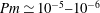 $\mathit{Pm}\simeq 10^{-5}{-}10^{-6}$
, meaning that magnetic diffusion is far stronger than viscous diffusion. This observation has motivated other teams (e.g. Weber et al.
Reference Weber, Galindo, Stefani, Weier and Wondrak2013) to use the QS approximation of MHD to describe fluid motions in which the magnetic Prandtl number
$\mathit{Pm}\simeq 10^{-5}{-}10^{-6}$
, meaning that magnetic diffusion is far stronger than viscous diffusion. This observation has motivated other teams (e.g. Weber et al.
Reference Weber, Galindo, Stefani, Weier and Wondrak2013) to use the QS approximation of MHD to describe fluid motions in which the magnetic Prandtl number
 $\mathit{Pm}$
no longer appears as an explicit parameter. This may present some technical advantages and could have been implemented in SFEMaNS, but we have preferred to keep a time-stepping strategy to be able to evaluate the influence of the magnetic Prandtl number.
$\mathit{Pm}$
no longer appears as an explicit parameter. This may present some technical advantages and could have been implemented in SFEMaNS, but we have preferred to keep a time-stepping strategy to be able to evaluate the influence of the magnetic Prandtl number.
As specified above, all of the numerical computations are performed using configuration II, i.e. all of the fields are restricted to the inner region
 $r\leqslant R$
. The aspect ratio
$r\leqslant R$
. The aspect ratio
 $h=H/R$
is finite to make the computational domain bounded. The initial data for (3.3) can be of two kinds: either we start from a slightly perturbed base state or we restart from a previously computed state. On the vertical walls, we impose the no-slip boundary condition on
$h=H/R$
is finite to make the computational domain bounded. The initial data for (3.3) can be of two kinds: either we start from a slightly perturbed base state or we restart from a previously computed state. On the vertical walls, we impose the no-slip boundary condition on
 $\boldsymbol{U}$
and the synthetic boundary condition (2.4) on the magnetic induction:
$\boldsymbol{U}$
and the synthetic boundary condition (2.4) on the magnetic induction:
 $$\begin{eqnarray}\boldsymbol{U}|_{r=1}=0,\quad \boldsymbol{e}_{r}\times \boldsymbol{B}|_{r=1}=\boldsymbol{e}_{z}.\end{eqnarray}$$
On the top and bottom lids, we use two different types of boundary conditions: either we impose periodicity on
 $\boldsymbol{U}$
,
$\boldsymbol{U}$
,
 $\boldsymbol{B}$
and
$\boldsymbol{B}$
and
 $P$
, or we impose the following conditions,
$P$
, or we impose the following conditions,
 $$\begin{eqnarray}\left.\begin{array}{@{}l@{}}U_{z}|_{z=0,h}=0,\quad [(\boldsymbol{{\rm\nabla}}\boldsymbol{U}+\boldsymbol{{\rm\nabla}}\boldsymbol{U}^{\text{T}})\boldsymbol{\cdot }\boldsymbol{e}_{z}]\times \boldsymbol{e}_{z}|_{z=0,h}=0\\ B_{z}|_{z=0,h}=0,\quad (\boldsymbol{{\rm\nabla}}\times \boldsymbol{B})\times \boldsymbol{e}_{z}|_{z=0,h}=0,\end{array}\right\}\end{eqnarray}$$
meaning that the lids are impenetrable, the tangential component of the stress is zero, the magnetic induction is tangential and the electrical current is normal to the top and bottom lids. We henceforth refer to these two sets of top/bottom boundary conditions as periodic TB-BC and stress-free TB-BC. The no-slip boundary conditions are not used in this article on the top and bottom lids because the linear stability analysis (done in § 4.3.1) is significantly easier to perform with periodic or stress-free TB-BC. We use these TB-BC in the numerical simulations to be able to make comparisons with the linear stability analysis from § 4. We expect the effect of this boundary condition not to be significant for vessels of sufficiently large aspect ratio. The effect of realistic no-slip boundary conditions on the top and bottom plates have been studied in Weber et al. (Reference Weber, Galindo, Stefani, Weier and Wondrak2013, Reference Weber, Galindo, Stefani and Weier2014). The initial data, the boundary conditions and the value of
 $h$
that we choose to perform computations will always be specified locally in the text.
$h$
that we choose to perform computations will always be specified locally in the text.
We will perform simulations for different choices of the parameters
 $\mathit{Ha}$
,
$\mathit{Ha}$
,
 $\mathit{Pm}$
and
$\mathit{Pm}$
and
 $h$
. Qualitative behaviours will be illustrated in the form of snapshots. Quantitative results will also be given. For instance, recalling the discrete representation of the velocity field (3.1), we will compute
$h$
. Qualitative behaviours will be illustrated in the form of snapshots. Quantitative results will also be given. For instance, recalling the discrete representation of the velocity field (3.1), we will compute
 $$\begin{eqnarray}u_{m}(t)=\sqrt{\frac{2}{h}\int _{0}^{1}\int _{0}^{h}(\Vert \boldsymbol{U}_{m}^{c}\Vert ^{2}+\Vert \boldsymbol{U}_{m}^{s}\Vert ^{2})r\,\text{d}r\,\text{d}z},\quad 0\leqslant m\leqslant M,\end{eqnarray}$$
the volume-averaged root-mean-square (r.m.s.) velocity of the Fourier mode
 $m$
.
$m$
.
Tayler instability simulations will be done by using the base state (2.2) augmented with random noise. Since in the linear regime the Tayler instability only grows along the Fourier mode
 $m=1$
, we then expect that
$m=1$
, we then expect that
 $$\begin{eqnarray}u_{1}(t)\sim \text{e}^{{\it\gamma}_{a}t},\end{eqnarray}$$
where
 ${\it\gamma}_{a}\geqslant 0$
is called the growth rate. The suffix ‘
${\it\gamma}_{a}\geqslant 0$
is called the growth rate. The suffix ‘
 $a$
’ refers to the Alfvén time units that we use in SFEMaNS and is added to avoid confusion with the growth rate
$a$
’ refers to the Alfvén time units that we use in SFEMaNS and is added to avoid confusion with the growth rate
 ${\it\gamma}$
that will be defined in the theoretical § 4. The growth rate
${\it\gamma}$
that will be defined in the theoretical § 4. The growth rate
 ${\it\gamma}_{a}$
will be evaluated numerically. The analysis of the nonlinear regime of the Tayler instability (Weber et al.
Reference Weber, Galindo, Stefani and Weier2014) is important to be able to estimate how strong the flow may become; this will be done by using the total specific kinetic energy:
${\it\gamma}_{a}$
will be evaluated numerically. The analysis of the nonlinear regime of the Tayler instability (Weber et al.
Reference Weber, Galindo, Stefani and Weier2014) is important to be able to estimate how strong the flow may become; this will be done by using the total specific kinetic energy:
 $$\begin{eqnarray}\mathit{K}_{a}=\mathop{\sum }_{m=0}^{M}(1+{\it\delta}_{m0})\frac{{\rm\pi}}{2}\int _{0}^{1}\int _{0}^{h}\left(\Vert \boldsymbol{U}_{m}^{c}\Vert ^{2}+\Vert \boldsymbol{U}_{m}^{s}\Vert ^{2}\right)r\,\text{d}r\,\text{d}z.\end{eqnarray}$$
We will also report the volume-averaged r.m.s. total velocity
 $$\begin{eqnarray}u_{rms,a}=\sqrt{2\mathit{K }_{a}/({\rm\pi}h)}.\end{eqnarray}$$
The phenomenology of the nonlinear transition will be discussed, and differences between periodic and stress-free boundary conditions will be analysed.
3.2. Cylinder with aspect ratio
 $h=2$
$h=2$

3.2.1. Periodic TB-BC
We first study the Tayler instability in a periodic cylinder of aspect ratio
 $h=2$
. The instability is observed for
$h=2$
. The instability is observed for
 $\mathit{Pm}=10^{-2}$
and
$\mathit{Pm}=10^{-2}$
and
 $\mathit{Ha}=24$
, and two types of growing modes with different symmetries are observed, see figure 2. Helicoidal structures (figure 2
a,b) are found for generically random initial data, but the mode shown in figure 2(c,d) is also obtained if the phase between the initial velocity and magnetic fields is set to
$\mathit{Ha}=24$
, and two types of growing modes with different symmetries are observed, see figure 2. Helicoidal structures (figure 2
a,b) are found for generically random initial data, but the mode shown in figure 2(c,d) is also obtained if the phase between the initial velocity and magnetic fields is set to
 ${\rm\pi}/2$
. This mode is composed of two counter-rotating vortices (figure 2
c) and a pair of oppositely oriented
${\rm\pi}/2$
. This mode is composed of two counter-rotating vortices (figure 2
c) and a pair of oppositely oriented
 $b_{z}$
blobs (figure 2
d). Both modes have exactly the same growth rate
$b_{z}$
blobs (figure 2
d). Both modes have exactly the same growth rate
 ${\it\gamma}_{a}=0.0187$
(i.e. they live in the same four-dimensional eigenspace; each mode comes in pair due to the symmetries of the problem, see § 4.3.1) and their wavelength is equal to the height of the domain. The vertical position of all the eigenmodes is arbitrary owing to the periodicity along the vertical direction.
${\it\gamma}_{a}=0.0187$
(i.e. they live in the same four-dimensional eigenspace; each mode comes in pair due to the symmetries of the problem, see § 4.3.1) and their wavelength is equal to the height of the domain. The vertical position of all the eigenmodes is arbitrary owing to the periodicity along the vertical direction.

Figure 2. Periodic TB-BC with
 $h=2$
, unstable Tayler mode at
$h=2$
, unstable Tayler mode at
 $\mathit{Ha}=24$
and
$\mathit{Ha}=24$
and
 $\mathit{Pm}=10^{-2}$
: (a)
$\mathit{Pm}=10^{-2}$
: (a)
 $\boldsymbol{U}$
, coloured by
$\boldsymbol{U}$
, coloured by
 $U_{z}$
; (b) isosurface of
$U_{z}$
; (b) isosurface of
 $B_{z}$
; (c)
$B_{z}$
; (c)
 $\boldsymbol{U}$
, coloured by
$\boldsymbol{U}$
, coloured by
 $U_{z}$
; (d) isosurface of
$U_{z}$
; (d) isosurface of
 $B_{z}$
. A growing helicoidal mode (a) and (b) is observed for general initial conditions, but non-helicoidal modes (c) and (d) can also be observed when the phase between the initial velocity and magnetic fields is
$B_{z}$
. A growing helicoidal mode (a) and (b) is observed for general initial conditions, but non-helicoidal modes (c) and (d) can also be observed when the phase between the initial velocity and magnetic fields is
 ${\rm\pi}/2$
.
${\rm\pi}/2$
.

Figure 3. The r.m.s. velocity
 $u_{1}(t)$
versus time at
$u_{1}(t)$
versus time at
 $\mathit{Pm}=10^{-2}$
and for different
$\mathit{Pm}=10^{-2}$
and for different
 $\mathit{Ha}$
numbers. Periodic cylinder with aspect ratio
$\mathit{Ha}$
numbers. Periodic cylinder with aspect ratio
 $h=2$
.
$h=2$
.
To better evaluate the importance of the parameters
 $\mathit{Pm}$
and
$\mathit{Pm}$
and
 $\mathit{Ha}$
, we now explore the ranges
$\mathit{Ha}$
, we now explore the ranges
 $\mathit{Pm}\in \{1,10^{-2},10^{-4},10^{-6}\}$
and
$\mathit{Pm}\in \{1,10^{-2},10^{-4},10^{-6}\}$
and
 $\mathit{Ha}\in \{20,24,30,35,40,100\}$
. For instance, we show in figure 3 the time evolution of the r.m.s. velocity
$\mathit{Ha}\in \{20,24,30,35,40,100\}$
. For instance, we show in figure 3 the time evolution of the r.m.s. velocity
 $u_{1}(t)$
for
$u_{1}(t)$
for
 $\mathit{Pm}=10^{-2}$
and
$\mathit{Pm}=10^{-2}$
and
 $\mathit{Ha}\in \{20,24,30,35,40,100\}$
. The exponential growth (positive or negative) of the Tayler instability in the linear regime clearly appears as straight lines in the semilogarithmic representation. For each pair of parameters
$\mathit{Ha}\in \{20,24,30,35,40,100\}$
. The exponential growth (positive or negative) of the Tayler instability in the linear regime clearly appears as straight lines in the semilogarithmic representation. For each pair of parameters
 $(\mathit{Pm},\mathit{Ha})$
, the growth rate
$(\mathit{Pm},\mathit{Ha})$
, the growth rate
 ${\it\gamma}_{a}$
is estimated by linear fit from these plots. The results are compiled in table 1 (left part). Apart from the values obtained for
${\it\gamma}_{a}$
is estimated by linear fit from these plots. The results are compiled in table 1 (left part). Apart from the values obtained for
 $\mathit{Pm}=1$
, we observe that
$\mathit{Pm}=1$
, we observe that
 ${\it\gamma}_{a}\sim \sqrt{\mathit{Pm}}$
. An explanation for this behaviour and a detailed comparison with the linear stability theory will be presented in § 4.3. Linear interpolation of the measured
${\it\gamma}_{a}\sim \sqrt{\mathit{Pm}}$
. An explanation for this behaviour and a detailed comparison with the linear stability theory will be presented in § 4.3. Linear interpolation of the measured
 ${\it\gamma}_{a}$
allows us to estimate the threshold
${\it\gamma}_{a}$
allows us to estimate the threshold
 $\mathit{Ha}_{c}$
, i.e. when
$\mathit{Ha}_{c}$
, i.e. when
 ${\it\gamma}_{a}=0$
. The threshold values
${\it\gamma}_{a}=0$
. The threshold values
 $\mathit{Ha}_{c}$
thus obtained are reported in table 1 (right part);
$\mathit{Ha}_{c}$
thus obtained are reported in table 1 (right part);
 $\mathit{Ha}_{c}$
is fairly independent of
$\mathit{Ha}_{c}$
is fairly independent of
 $\mathit{Pm}$
, in agreement with the linear stability analysis of Rüdiger et al. (Reference Rüdiger, Schultz and Gellert2011, Reference Rüdiger, Gellert, Schultz, Strassmeier, Stefani, Gundrum, Seilmayer and Gerbeth2012).
$\mathit{Pm}$
, in agreement with the linear stability analysis of Rüdiger et al. (Reference Rüdiger, Schultz and Gellert2011, Reference Rüdiger, Gellert, Schultz, Strassmeier, Stefani, Gundrum, Seilmayer and Gerbeth2012).
Table 1. Growth rate
 ${\it\gamma}_{a}$
(left) and critical Hartmann number
${\it\gamma}_{a}$
(left) and critical Hartmann number
 $\mathit{Ha}_{c}$
(right) at various
$\mathit{Ha}_{c}$
(right) at various
 $\mathit{Pm}$
in a cylinder with aspect ratio
$\mathit{Pm}$
in a cylinder with aspect ratio
 $h=2$
and periodic TB-BC.
$h=2$
and periodic TB-BC.

We now follow the non-helicoidal structures of figure 2(c,d) in the nonlinear regime. The time evolution of the kinetic energy
 $\mathit{K}_{a}$
is reported in figure 4 for
$\mathit{K}_{a}$
is reported in figure 4 for
 $\mathit{Pm}=10^{-2},10^{-4},10^{-6}$
. The qualitative behaviour of
$\mathit{Pm}=10^{-2},10^{-4},10^{-6}$
. The qualitative behaviour of
 $\mathit{K}_{a}$
with respect to time is similar for the different values of
$\mathit{K}_{a}$
with respect to time is similar for the different values of
 $\mathit{Pm}$
investigated, but the amplitude of the realized flow dramatically decreases with
$\mathit{Pm}$
investigated, but the amplitude of the realized flow dramatically decreases with
 $\mathit{Pm}$
, indicating that a scaling law might exist. This point will be discussed in § 4. Table 2 shows the mean kinetic energy measured at saturation for various values of
$\mathit{Pm}$
, indicating that a scaling law might exist. This point will be discussed in § 4. Table 2 shows the mean kinetic energy measured at saturation for various values of
 $\mathit{Pm}$
and
$\mathit{Pm}$
and
 $\mathit{Ha}$
.
$\mathit{Ha}$
.

Figure 4. Time evolution of the kinetic energy
 $\mathit{K}_{a}$
for
$\mathit{K}_{a}$
for
 $h=2$
with periodic TB-BC and different
$h=2$
with periodic TB-BC and different
 $\mathit{Pm}$
: (a)
$\mathit{Pm}$
: (a)
 $\mathit{Pm}=10^{-2}$
; (b)
$\mathit{Pm}=10^{-2}$
; (b)
 $\mathit{Pm}=10^{-4}$
; (c)
$\mathit{Pm}=10^{-4}$
; (c)
 $\mathit{Pm}=10^{-6}$
. We restarted calculations varying
$\mathit{Pm}=10^{-6}$
. We restarted calculations varying
 $\mathit{Ha}$
as indicated in the figure.
$\mathit{Ha}$
as indicated in the figure.
Table 2. Kinetic energy at saturation for various
 $\mathit{Pm}$
and
$\mathit{Pm}$
and
 $\mathit{Ha}$
in a cylinder of aspect ratio
$\mathit{Ha}$
in a cylinder of aspect ratio
 $h=2$
and periodic TB-BC.
$h=2$
and periodic TB-BC.

For all of the values of
 $\mathit{Pm}$
explored, we observe that the shape of the steady-state solution at
$\mathit{Pm}$
explored, we observe that the shape of the steady-state solution at
 $\mathit{Ha}=24$
(i.e. near the threshold) is similar to that of the eigenvectors shown in figure 2(c,d). Two steady counter-rotating vortices have formed together with a pair of magnetic blobs in quadrature. Between
$\mathit{Ha}=24$
(i.e. near the threshold) is similar to that of the eigenvectors shown in figure 2(c,d). Two steady counter-rotating vortices have formed together with a pair of magnetic blobs in quadrature. Between
 $\mathit{Ha}=24$
and
$\mathit{Ha}=24$
and
 $\mathit{Ha}=30$
the flow becomes time-dependent. The oscillating velocity and magnetic fields that can be observed (not shown here) are similar to the time-periodic eigenmode observed at
$\mathit{Ha}=30$
the flow becomes time-dependent. The oscillating velocity and magnetic fields that can be observed (not shown here) are similar to the time-periodic eigenmode observed at
 $\mathit{Ha}=35$
. Figure 5 shows snapshots of the solution obtained at
$\mathit{Ha}=35$
. Figure 5 shows snapshots of the solution obtained at
 $\mathit{Ha}=35$
and
$\mathit{Ha}=35$
and
 $\mathit{Pm}=10^{-2}$
during one period (
$\mathit{Pm}=10^{-2}$
during one period (
 $t$
,
$t$
,
 $t+T/4$
,
$t+T/4$
,
 $t+T/2$
,
$t+T/2$
,
 $t+3T/4$
,
$t+3T/4$
,
 $t+T$
): there are two pulsating vortices in phase opposition. Table 3 shows the measured period as a function of
$t+T$
): there are two pulsating vortices in phase opposition. Table 3 shows the measured period as a function of
 $\mathit{Pm}$
and
$\mathit{Pm}$
and
 $\mathit{Ha}$
. The period decreases as
$\mathit{Ha}$
. The period decreases as
 $\mathit{Ha}$
increases. The time-periodic regime is observed for all values of
$\mathit{Ha}$
increases. The time-periodic regime is observed for all values of
 $\mathit{Pm}$
at
$\mathit{Pm}$
at
 $\mathit{Ha}=30$
and
$\mathit{Ha}=30$
and
 $\mathit{Ha}=35$
, but for
$\mathit{Ha}=35$
, but for
 $\mathit{Ha}=40$
the time-periodic state is observed only at
$\mathit{Ha}=40$
the time-periodic state is observed only at
 $\mathit{Pm}=10^{-2}$
; the dynamic becomes quasi-periodic for smaller values of the Prandtl number, i.e.
$\mathit{Pm}=10^{-2}$
; the dynamic becomes quasi-periodic for smaller values of the Prandtl number, i.e.
 $\mathit{Pm}=10^{-4}$
and
$\mathit{Pm}=10^{-4}$
and
 $\mathit{Pm}=10^{-6}$
(see figure 4
b,c). Since
$\mathit{Pm}=10^{-6}$
(see figure 4
b,c). Since
 $\mathit{Pm}=10^{-2}$
gives the same qualitative results as
$\mathit{Pm}=10^{-2}$
gives the same qualitative results as
 $\mathit{Pm}=10^{-4}$
and
$\mathit{Pm}=10^{-4}$
and
 $\mathit{Pm}=10^{-6}$
, we will use
$\mathit{Pm}=10^{-6}$
, we will use
 $\mathit{Pm}=10^{-2}$
in the parametric studies in the next sections.
$\mathit{Pm}=10^{-2}$
in the parametric studies in the next sections.

Figure 5. Periodic TB-BC,
 $h=2$
, time-periodic state at
$h=2$
, time-periodic state at
 $\mathit{Ha}=35$
and
$\mathit{Ha}=35$
and
 $\mathit{Pm}=10^{-2}$
: (a)
$\mathit{Pm}=10^{-2}$
: (a)
 $t$
and
$t$
and
 $t+T$
; (b)
$t+T$
; (b)
 $t+T/4$
; (c)
$t+T/4$
; (c)
 $t+T/2$
; (d)
$t+T/2$
; (d)
 $t+3T/4$
. Two pulsating vortices in phase opposition.
$t+3T/4$
. Two pulsating vortices in phase opposition.

Figure 6. Stress-free TB-BC,
 $h=2$
and
$h=2$
and
 $\mathit{Pm}=10^{-2}$
: competing eigenstates (a)
$\mathit{Pm}=10^{-2}$
: competing eigenstates (a)
 $\mathit{SF}$
-one and (b)
$\mathit{SF}$
-one and (b)
 $\mathit{SF}$
-half shown by vectors coloured by
$\mathit{SF}$
-half shown by vectors coloured by
 $U_{z}$
.
$U_{z}$
.
Table 3. Periodic TB-BC with
 $h=2$
: period of the system at
$h=2$
: period of the system at
 $\mathit{Ha}=30,35,40$
(this period corresponds to twice the period of the kinetic energy because the flow has two alternating vortices). QP stands for a quasi-periodic regime.
$\mathit{Ha}=30,35,40$
(this period corresponds to twice the period of the kinetic energy because the flow has two alternating vortices). QP stands for a quasi-periodic regime.

Table 4. Stress-free TB-BC with
 $h=2$
and
$h=2$
and
 $\mathit{Pm}=10^{-2}$
: growth rates for
$\mathit{Pm}=10^{-2}$
: growth rates for
 $\mathit{SF}$
-one and
$\mathit{SF}$
-one and
 $\mathit{SF}$
-half eigenstates.
$\mathit{SF}$
-half eigenstates.

3.2.2. Stress-free TB-BC
When the periodic TB-BC condition is replaced by the stress-free TB-BC, the eigenmodes that are observed are no longer helicoidal; actually, these modes can exist only in periodic boxes as will be shown in the theoretical § 4. Our computations show that two eigenmodes become unstable when
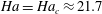 $\mathit{Ha}=\mathit{Ha}_{c}\approx 21.7$
. The dominant mode consists of two counter-rotating vortices filling the vessel; the corresponding growth rates and thresholds are the same as those found in the periodic case, see table 4. This mode is henceforth referred to as
$\mathit{Ha}=\mathit{Ha}_{c}\approx 21.7$
. The dominant mode consists of two counter-rotating vortices filling the vessel; the corresponding growth rates and thresholds are the same as those found in the periodic case, see table 4. This mode is henceforth referred to as
 $\mathit{SF}$
-one and is shown in figure 6(a). The second eigenmode is composed of a single vortex filling the vessel and is henceforth referred to as
$\mathit{SF}$
-one and is shown in figure 6(a). The second eigenmode is composed of a single vortex filling the vessel and is henceforth referred to as
 $\mathit{SF}$
-half, see table 4 and figure 6(b).
$\mathit{SF}$
-half, see table 4 and figure 6(b).
We now perform a simulation in the nonlinear regime to see how the
 $\mathit{SF}$
-one and
$\mathit{SF}$
-one and
 $\mathit{SF}$
-half modes compete. The time evolution of the kinetic energy is shown in figure 7(a) for
$\mathit{SF}$
-half modes compete. The time evolution of the kinetic energy is shown in figure 7(a) for
 $\mathit{Ha}=24$
, 30, 35. At
$\mathit{Ha}=24$
, 30, 35. At
 $\mathit{Ha}=30$
, starting from initial random noise, a state with one-wavelength (such as the
$\mathit{Ha}=30$
, starting from initial random noise, a state with one-wavelength (such as the
 $\mathit{SF}$
-one eigenvector, see figure 7
b) increases exponentially and reaches a maximum around
$\mathit{SF}$
-one eigenvector, see figure 7
b) increases exponentially and reaches a maximum around
 $t=195$
(see figure 7
a). Then, the kinetic energy decreases and reaches a minimum value at
$t=195$
(see figure 7
a). Then, the kinetic energy decreases and reaches a minimum value at
 $t=225$
. During this transition the number of vortices occupying the vessel changes from 2 to 1. The orientation of the axis of the vortices changes as well and rotates by
$t=225$
. During this transition the number of vortices occupying the vessel changes from 2 to 1. The orientation of the axis of the vortices changes as well and rotates by
 ${\rm\pi}/2$
(see figure 7
b–e). The kinetic energy increases afterwards and reaches a plateau at
${\rm\pi}/2$
(see figure 7
b–e). The kinetic energy increases afterwards and reaches a plateau at
 $t=350$
. The final state is composed of one steady vortex and one magnetic field blob resembling the
$t=350$
. The final state is composed of one steady vortex and one magnetic field blob resembling the
 $\mathit{SF}$
-half eigenvector.
$\mathit{SF}$
-half eigenvector.

Figure 7. Stress-free TB-BC,
 $h=2$
and
$h=2$
and
 $\mathit{Pm}=10^{-2}$
. (a) Time evolution of the kinetic energy in the nonlinear regime:
$\mathit{Pm}=10^{-2}$
. (a) Time evolution of the kinetic energy in the nonlinear regime:
 $\mathit{Ha}=24,30,35$
. (b–e) Competition between two states at
$\mathit{Ha}=24,30,35$
. (b–e) Competition between two states at
 $\mathit{Ha}=30$
: (b)
$\mathit{Ha}=30$
: (b)
 $t=150$
,
$t=150$
,
 $Oxz$
-plane; (c)
$Oxz$
-plane; (c)
 $t=200$
,
$t=200$
,
 $Oxz$
-plane; (d)
$Oxz$
-plane; (d)
 $t=250$
,
$t=250$
,
 $Oxz$
-plane; (e)
$Oxz$
-plane; (e)
 $t=300$
,
$t=300$
,
 $Oyz$
-plane. The two vortices of the most unstable linear eigenmode merge into one vortex and rotate by
$Oyz$
-plane. The two vortices of the most unstable linear eigenmode merge into one vortex and rotate by
 ${\rm\pi}/2$
for
${\rm\pi}/2$
for
 $200\leqslant t\leqslant 250$
. Note the change of view point at
$200\leqslant t\leqslant 250$
. Note the change of view point at
 $t=300$
.
$t=300$
.
3.3. Cylinder with optimal aspect ratio
$h=2.77$

The linear theory developed in § 4.3.2 predicts that a cylinder of aspect ratio
 $h=2.77$
gives the lowest threshold on the Hartmann number,
$h=2.77$
gives the lowest threshold on the Hartmann number,
 $\mathit{Ha}_{c,\ast }=19.296$
. We will use this optimal cylinder height in the LMB configuration. Our numerical estimation of the threshold on the Hartmann number is
$\mathit{Ha}_{c,\ast }=19.296$
. We will use this optimal cylinder height in the LMB configuration. Our numerical estimation of the threshold on the Hartmann number is
 $\mathit{Ha}_{c}\approx 19.4$
; the linearly unstable modes in the periodic and stress-free TB-BC cases are similar to those obtained for
$\mathit{Ha}_{c}\approx 19.4$
; the linearly unstable modes in the periodic and stress-free TB-BC cases are similar to those obtained for
 $h=2$
and are shown in figure 8.
$h=2$
and are shown in figure 8.

Figure 8. The optimal box
 $h=2.77$
at
$h=2.77$
at
 $\mathit{Ha}=24$
and
$\mathit{Ha}=24$
and
 $\mathit{Pm}=10^{-2}$
: eigenmode for (a) periodic TB-BC and (b) stress-free TB-BC.
$\mathit{Pm}=10^{-2}$
: eigenmode for (a) periodic TB-BC and (b) stress-free TB-BC.
We now perform nonlinear runs for the two types of boundary conditions. For the periodic case, we have performed a set of computations starting from different initial conditions (see figure 9
a). Starting from random noise at
 $\mathit{Ha}=24$
, the system converges to a steady state with one wavelength in the vertical box (two counter-rotating vortices, see figure 8
a). Restarting from this state and increasing the Hartmann number to
$\mathit{Ha}=24$
, the system converges to a steady state with one wavelength in the vertical box (two counter-rotating vortices, see figure 8
a). Restarting from this state and increasing the Hartmann number to
 $\mathit{Ha}=35$
leads to a first plateau in the kinetic energy. This is not the asymptotic state since performing another run with
$\mathit{Ha}=35$
leads to a first plateau in the kinetic energy. This is not the asymptotic state since performing another run with
 $\mathit{Ha}=35$
using as initial data a state computed at
$\mathit{Ha}=35$
using as initial data a state computed at
 $\mathit{Ha}=40$
(curve titled ‘
$\mathit{Ha}=40$
(curve titled ‘
 $\mathit{Ha}=35$
’ at time
$\mathit{Ha}=35$
’ at time
 $t\geqslant 1170$
) leads to a time-periodic regime. The dynamic system obtained at
$t\geqslant 1170$
) leads to a time-periodic regime. The dynamic system obtained at
 $\mathit{Ha}=40$
is also time-periodic with two vortices pulsating in phase opposition (similar to those in figure 5). Decreasing the Hartmann number from
$\mathit{Ha}=40$
is also time-periodic with two vortices pulsating in phase opposition (similar to those in figure 5). Decreasing the Hartmann number from
 $\mathit{Ha}=40$
to
$\mathit{Ha}=40$
to
 $\mathit{Ha}=30$
yields a steady state (curve titled ‘
$\mathit{Ha}=30$
yields a steady state (curve titled ‘
 $\mathit{Ha}=30$
’ at time
$\mathit{Ha}=30$
’ at time
 $t\geqslant 1170$
). Therefore, the transition from a steady state to an oscillating regime occurs for
$t\geqslant 1170$
). Therefore, the transition from a steady state to an oscillating regime occurs for
 $\mathit{Ha}>30$
. On the other hand, the stress-free case leads to a steady state with one wavelength for all of the Hartmann numbers that we have explored,
$\mathit{Ha}>30$
. On the other hand, the stress-free case leads to a steady state with one wavelength for all of the Hartmann numbers that we have explored,
 $\mathit{Ha}\in \{24,35,40,50\}$
. The steady-state nature of the various cases is visible on the time history of the kinetic energy, see figure 8(b). These nonlinear runs clearly illustrate that periodical TB-BC allow for dynamical behaviour that is not observed with stress-free TB-BC. This is entirely due to confinement by impermeable top and bottom lids. Since no-slip boundaries are also impermeable, we expect similar dynamics as in the stress-free TB-BC case.
$\mathit{Ha}\in \{24,35,40,50\}$
. The steady-state nature of the various cases is visible on the time history of the kinetic energy, see figure 8(b). These nonlinear runs clearly illustrate that periodical TB-BC allow for dynamical behaviour that is not observed with stress-free TB-BC. This is entirely due to confinement by impermeable top and bottom lids. Since no-slip boundaries are also impermeable, we expect similar dynamics as in the stress-free TB-BC case.

Figure 9. Time evolution of the kinetic energy for
 $h=2.77$
and
$h=2.77$
and
 $\mathit{Pm}=10^{-2}$
with different boundary conditions: (a) periodic TB-BC; (b) stress-free TB-BC.
$\mathit{Pm}=10^{-2}$
with different boundary conditions: (a) periodic TB-BC; (b) stress-free TB-BC.
4. Theoretical analysis of Tayler’s instability
4.1. Perturbation problem
We now investigate the linear stability theory of the Tayler instability. We start by writing the non-dimensional perturbation equations using the following units:
 $$\begin{eqnarray}[\boldsymbol{x}]=R,\quad [t]={\it\rho}/({\it\sigma}B_{0}^{2}),\quad [\boldsymbol{u}]=[\boldsymbol{x}]/[\boldsymbol{t}],\quad [\boldsymbol{b}]={\it\sigma}{\it\mu}_{0}[\boldsymbol{u}][\boldsymbol{x}]B_{0},\quad [p]={\it\rho}[\boldsymbol{u}]^{2},\end{eqnarray}$$
to scale the space, the time, the velocity, the magnetic field and the pressure. These units are different from those used in the previous section but they are better adapted to describe the Tayler instability in the QS regime. The time scale is such that the magnetic interaction parameter
 $N:={\it\sigma}B_{0}^{2}R/{\it\rho}[\boldsymbol{u}]$
is equal to 1.
$N:={\it\sigma}B_{0}^{2}R/{\it\rho}[\boldsymbol{u}]$
is equal to 1.
We inject
 $\boldsymbol{U}=\boldsymbol{U}_{b}+\boldsymbol{u}$
,
$\boldsymbol{U}=\boldsymbol{U}_{b}+\boldsymbol{u}$
,
 $\boldsymbol{B}=\boldsymbol{B}_{b}+\boldsymbol{b}$
,
$\boldsymbol{B}=\boldsymbol{B}_{b}+\boldsymbol{b}$
,
 $P=P_{b}+p$
into (2.1), where
$P=P_{b}+p$
into (2.1), where
 $\boldsymbol{u}$
,
$\boldsymbol{u}$
,
 $\boldsymbol{b}$
and
$\boldsymbol{b}$
and
 $p$
are infinitesimal perturbations, and find that
$p$
are infinitesimal perturbations, and find that
 $$\begin{eqnarray}\displaystyle \left.\begin{array}{@{}c@{}}\displaystyle \partial _{t}\boldsymbol{u}=-\boldsymbol{{\rm\nabla}}q+\left[r\boldsymbol{e}_{{\it\theta}}\boldsymbol{\cdot }\boldsymbol{{\rm\nabla}}\boldsymbol{b}+\boldsymbol{b}\boldsymbol{\cdot }\boldsymbol{{\rm\nabla}}(r\boldsymbol{e}_{{\it\theta}})\right]+\mathit{Ha}^{-2}{\rm\Delta}\boldsymbol{u}+\boldsymbol{N}_{u},\\ \displaystyle \mathit{Pm}\mathit{Ha}^{2}\partial _{t}\boldsymbol{b}=\boldsymbol{{\rm\nabla}}\times (\boldsymbol{u}\times r\boldsymbol{e}_{{\it\theta}})+{\rm\Delta}\boldsymbol{b}+\boldsymbol{N}_{b},\\ \displaystyle \boldsymbol{{\rm\nabla}}\boldsymbol{\cdot }\boldsymbol{u}=\boldsymbol{{\rm\nabla}}\boldsymbol{\cdot }\boldsymbol{b}=0,\end{array}\right\} & & \displaystyle\end{eqnarray}$$
where we have introduced a modified pressure field
 $q$
defined as
$q$
defined as
 $$\begin{eqnarray}q=p+b_{{\it\theta}}r+{\textstyle \frac{1}{2}}\mathit{Pm}\mathit{Ha}^{2}\Vert \boldsymbol{b}\Vert ^{2},\end{eqnarray}$$
and
 $\boldsymbol{N}_{u}\boldsymbol{N}_{b}$
are nonlinear terms:
$\boldsymbol{N}_{u}\boldsymbol{N}_{b}$
are nonlinear terms:
 $$\begin{eqnarray}\displaystyle & \boldsymbol{N}_{u}=-(\boldsymbol{u}\boldsymbol{\cdot }\boldsymbol{{\rm\nabla}})\boldsymbol{u}+\mathit{Pm}\mathit{Ha}^{2}(\boldsymbol{b}\boldsymbol{\cdot }\boldsymbol{{\rm\nabla}})\boldsymbol{b} & \displaystyle\end{eqnarray}$$
 $$\begin{eqnarray}\displaystyle & \boldsymbol{N}_{b}=-\mathit{Pm}\mathit{Ha}^{2}(\boldsymbol{u}\boldsymbol{\cdot }\boldsymbol{{\rm\nabla}})\boldsymbol{b}+\mathit{Pm}\mathit{Ha}^{2}(\boldsymbol{b}\boldsymbol{\cdot }\boldsymbol{{\rm\nabla}})\boldsymbol{u}. & \displaystyle\end{eqnarray}$$
 $\mathit{Pm}\simeq 10^{-5}{-}10^{-8}$
in real liquid metals. In the so-called QS limit, all of the terms weighted by
$\mathit{Pm}\simeq 10^{-5}{-}10^{-8}$
in real liquid metals. In the so-called QS limit, all of the terms weighted by
 $\mathit{Pm}$
are neglected. The combination
$\mathit{Pm}$
are neglected. The combination
 $\sqrt{\mathit{Pm}}\mathit{Ha}$
is also sometimes called the Lundquist number. We do not adopt the QS approach immediately since our aim is to specify for which range of the parameters
$\sqrt{\mathit{Pm}}\mathit{Ha}$
is also sometimes called the Lundquist number. We do not adopt the QS approach immediately since our aim is to specify for which range of the parameters
 $\mathit{Ha}$
and
$\mathit{Ha}$
and
 $\mathit{Pm}$
the QS limit applies.
$\mathit{Pm}$
the QS limit applies.
For configuration I, we impose the no-slip condition on the velocity perturbations at
 $r=1$
and the continuity of the magnetic induction across the cylindrical boundary
$r=1$
and the continuity of the magnetic induction across the cylindrical boundary
 $r=1$
:
$r=1$
:
 $$\begin{eqnarray}\text{BC I:}~\boldsymbol{u}|_{r=1^{-}}=0,\quad \boldsymbol{b}|_{r=1^{-}}=\boldsymbol{{\rm\nabla}}{\it\psi}|_{r=1^{+}},\end{eqnarray}$$
where outside the cylinder we look for
 $\boldsymbol{b}$
in potential form
$\boldsymbol{b}$
in potential form
 $\boldsymbol{b}:=\boldsymbol{{\rm\nabla}}{\it\psi}$
with
$\boldsymbol{b}:=\boldsymbol{{\rm\nabla}}{\it\psi}$
with
 ${\rm\nabla}^{2}{\it\psi}=0$
. Note that this hypothesis, also used by Tayler, is somewhat restrictive since it excludes external fields that perhaps could be more complex (the external region is a torus and thus not simply connected). In configuration II, we impose again the no-slip condition on the velocity, but this time the perturbations of the tangential magnetic field must be zero on the lateral boundary
${\rm\nabla}^{2}{\it\psi}=0$
. Note that this hypothesis, also used by Tayler, is somewhat restrictive since it excludes external fields that perhaps could be more complex (the external region is a torus and thus not simply connected). In configuration II, we impose again the no-slip condition on the velocity, but this time the perturbations of the tangential magnetic field must be zero on the lateral boundary
 $r=1$
,
$r=1$
,
 $$\begin{eqnarray}\text{BC II:}~\boldsymbol{u}|_{r=1^{-}}=0,\quad \boldsymbol{e}_{r}\times \boldsymbol{b}|_{r=1^{-}}=0.\end{eqnarray}$$
4.2. Linear stability analysis: method
4.2.1. General solution
In the limit of vanishing perturbations
 $\boldsymbol{u},\boldsymbol{b},q\rightarrow 0$
, we neglect the nonlinear terms
$\boldsymbol{u},\boldsymbol{b},q\rightarrow 0$
, we neglect the nonlinear terms
 $\boldsymbol{N}_{u}$
and
$\boldsymbol{N}_{u}$
and
 $\boldsymbol{N}_{b}$
. The linearized perturbation equations can be decoupled in terms of the modified pressure, which for all non-axisymmetric perturbations, leads to the following tenth-order Master equation
$\boldsymbol{N}_{b}$
. The linearized perturbation equations can be decoupled in terms of the modified pressure, which for all non-axisymmetric perturbations, leads to the following tenth-order Master equation
 $$\begin{eqnarray}\left\{\left[(\partial _{t}-\mathit{Ha}^{-2}{\it\Delta})(\mathit{Pm}\mathit{Ha}^{2}\partial _{t}-{\it\Delta})-\partial _{{\it\theta}{\it\theta}}^{2}\right]^{2}{\it\Delta}+4\partial _{{\it\theta}{\it\theta}}^{2}\partial _{zz}^{2}\right\}\partial _{{\it\theta}}q=0.\end{eqnarray}$$
The decoupling process is quite technical and similar to Tayler’s original approach. The details are reported in the appendix A. We consider the following ansatz with an harmonic structure with respect to
 $z$
,
$z$
,
 ${\it\theta}$
and
${\it\theta}$
and
 $t$
:
$t$
:
 $$\begin{eqnarray}q(r,{\it\theta},z,t)=\mathop{\sum }_{j=1}^{5}P_{j}\text{J}_{m}(k_{j}r)\text{e}^{\text{i}m{\it\theta}}\text{e}^{\text{i}lz}\text{e}^{{\it\gamma}t},\end{eqnarray}$$
where
 $m\in \mathbb{Z}$
,
$m\in \mathbb{Z}$
,
 $l\in \mathbb{R}$
are azimuthal and vertical wavenumbers,
$l\in \mathbb{R}$
are azimuthal and vertical wavenumbers,
 ${\it\gamma}\in \mathbb{C}$
is the unknown complex-valued growth rate,
${\it\gamma}\in \mathbb{C}$
is the unknown complex-valued growth rate,
 $P_{j}$
are five arbitrary complex-valued coefficients, and
$P_{j}$
are five arbitrary complex-valued coefficients, and
 $k_{j}\in \mathbb{C}$
are five different radial wavenumbers with the convention that
$k_{j}\in \mathbb{C}$
are five different radial wavenumbers with the convention that
 $\text{Re}(k_{j})\leqslant 0$
. The functions
$\text{Re}(k_{j})\leqslant 0$
. The functions
 $\text{J}_{m}(k_{j}r)$
are Bessel functions of the first kind. No Bessel functions of the second kind
$\text{J}_{m}(k_{j}r)$
are Bessel functions of the first kind. No Bessel functions of the second kind
 $\text{Y}_{m}(k_{j}r)$
are involved since
$\text{Y}_{m}(k_{j}r)$
are involved since
 $r=0$
is part of the fluid domain. The radial wavenumbers
$r=0$
is part of the fluid domain. The radial wavenumbers
 $k_{j}$
are chosen so that the numbers
$k_{j}$
are chosen so that the numbers
 $z_{j}=k_{j}^{2}+l^{2},j=1,\dots ,5$
are the roots of the fifth-order characteristic polynomial
$z_{j}=k_{j}^{2}+l^{2},j=1,\dots ,5$
are the roots of the fifth-order characteristic polynomial
 $$\begin{eqnarray}Q(z)=[({\it\gamma}+\mathit{Ha}^{-2}z)(\mathit{Pm}\mathit{Ha}^{2}{\it\gamma}+z)+m^{2}]^{2}z-4m^{2}l^{2}\end{eqnarray}$$
associated with (4.8). This implicitly fixes the five numbers
 $k_{j}$
as functions of
$k_{j}$
as functions of
 $m$
,
$m$
,
 $l$
,
$l$
,
 $\mathit{Ha}$
,
$\mathit{Ha}$
,
 $\mathit{Pm}$
and
$\mathit{Pm}$
and
 ${\it\gamma}$
. The dependence of
${\it\gamma}$
. The dependence of
 $k_{j}$
on
$k_{j}$
on
 $m$
,
$m$
,
 $l$
,
$l$
,
 $\mathit{Ha}$
,
$\mathit{Ha}$
,
 $\mathit{Pm}$
and
$\mathit{Pm}$
and
 ${\it\gamma}$
is implicit not only because no analytical formula exists for the roots of
${\it\gamma}$
is implicit not only because no analytical formula exists for the roots of
 $Q(z)$
, but also because
$Q(z)$
, but also because
 ${\it\gamma}$
is still unknown at the moment. By back-substituting the ansatz (4.9) into the original equations, we can calculate all of the other fields
${\it\gamma}$
is still unknown at the moment. By back-substituting the ansatz (4.9) into the original equations, we can calculate all of the other fields
 $$\begin{eqnarray}\left.\begin{array}{@{}l@{}}\displaystyle u_{\pm }=\mathop{\sum }_{j=1}^{5}P_{j}\frac{\pm k_{j}(\mathit{Pm}\mathit{Ha}^{2}{\it\gamma}+z_{j})}{f_{j}+m(m\pm 2)}\text{J}_{m\pm 1}(k_{j}r)\text{e}^{\text{i}m{\it\theta}}\text{e}^{\text{i}lz}\text{e}^{{\it\gamma}t},\\ \displaystyle b_{\pm }=\mathop{\sum }_{j=1}^{5}P_{j}\frac{\pm \text{i}mk_{j}}{f_{j}+m(m\pm 2)}\text{J}_{m\pm 1}(k_{j}r)\text{e}^{\text{i}m{\it\theta}}\text{e}^{\text{i}lz}\text{e}^{{\it\gamma}t},\\ \displaystyle u_{z}=\mathop{\sum }_{j=1}^{5}P_{j}\frac{-\text{i}l(\mathit{Pm}\mathit{Ha}^{2}{\it\gamma}+z_{j})}{f_{j}+m^{2}}\text{J}_{m}(k_{j}r)\text{e}^{\text{i}m{\it\theta}}\text{e}^{\text{i}lz}\text{e}^{{\it\gamma}t},\\ \displaystyle b_{z}=\mathop{\sum }_{j=1}^{5}P_{j}\frac{ml}{f_{j}+m^{2}}\text{J}_{m}(k_{j}r)\text{e}^{\text{i}m{\it\theta}}\text{e}^{\text{i}lz}\text{e}^{{\it\gamma}t},\end{array}\right\}\end{eqnarray}$$
where we defined
 $f_{j}=({\it\gamma}+\mathit{Ha}^{-2}z_{j})(\mathit{Pm}\mathit{Ha}^{2}{\it\gamma}+z_{j})$
and
$f_{j}=({\it\gamma}+\mathit{Ha}^{-2}z_{j})(\mathit{Pm}\mathit{Ha}^{2}{\it\gamma}+z_{j})$
and
 $u_{\pm }=u_{r}\pm \text{i}u_{{\it\theta}}$
and
$u_{\pm }=u_{r}\pm \text{i}u_{{\it\theta}}$
and
 $b_{\pm }=b_{r}\pm \text{i}b_{{\it\theta}}$
. This fixes all of the fields in terms of five arbitrary constants
$b_{\pm }=b_{r}\pm \text{i}b_{{\it\theta}}$
. This fixes all of the fields in terms of five arbitrary constants
 $P_{j}$
. Note that the notation
$P_{j}$
. Note that the notation
 $u_{\pm }=u_{r}\pm \text{i}u_{{\it\theta}}$
and
$u_{\pm }=u_{r}\pm \text{i}u_{{\it\theta}}$
and
 $b_{\pm }=b_{r}\pm \text{i}b_{{\it\theta}}$
allows us to recognize simple structures in the solution.
$b_{\pm }=b_{r}\pm \text{i}b_{{\it\theta}}$
allows us to recognize simple structures in the solution.
In configuration I, the interior magnetic induction must match an exterior field that derives from an harmonic potential of the following form
 $$\begin{eqnarray}{\it\psi}(r,z,{\it\theta},t)=D\mathit{K}_{m}(lr)\text{e}^{\text{i}m{\it\theta}}\text{e}^{\text{i}lz}\text{e}^{{\it\gamma}t},\end{eqnarray}$$
where
 $D\in \mathbb{C}$
is a sixth arbitrary constant, and
$D\in \mathbb{C}$
is a sixth arbitrary constant, and
 $\mathit{K}_{m}$
is a modified Bessel function of the second kind. The associated magnetic field is
$\mathit{K}_{m}$
is a modified Bessel function of the second kind. The associated magnetic field is
 $$\begin{eqnarray}\left.\begin{array}{@{}c@{}}b_{\pm }=D(-l)\mathit{K}_{m\pm 1}(lr)\text{e}^{\text{i}m{\it\theta}}\text{e}^{\text{i}lz}\text{e}^{{\it\gamma}t},\\ b_{z}=D(\text{i}l)\mathit{K}_{m}(lr)\text{e}^{\text{i}m{\it\theta}}\text{e}^{\text{i}lz}\text{e}^{{\it\gamma}t}.\end{array}\right\}\end{eqnarray}$$
At this point, we have found solutions of the homogenous problem inside and outside the cylinder in terms of six arbitrary coefficients. There are exactly six boundary/transmission conditions (4.6) and it is thus possible to find a set of six homogenous algebraic equations for the constants
 $P_{1},\dots ,P_{5},D$
. Upon defining
$P_{1},\dots ,P_{5},D$
. Upon defining
 $\unicode[STIX]{x1D651}=[P_{1},P_{2},P_{3},P_{4},P_{5},D]^{\text{T}}$
, in matrix notation we have
$\unicode[STIX]{x1D651}=[P_{1},P_{2},P_{3},P_{4},P_{5},D]^{\text{T}}$
, in matrix notation we have
 $$\begin{eqnarray}\unicode[STIX]{x1D648}({\it\gamma},m,l,\mathit{Ha},\mathit{Pm})\unicode[STIX]{x1D651}=0,\end{eqnarray}$$
where
 $\unicode[STIX]{x1D648}\in \mathbb{C}^{6\times 6}$
is a complex-valued matrix depending on
$\unicode[STIX]{x1D648}\in \mathbb{C}^{6\times 6}$
is a complex-valued matrix depending on
 ${\it\gamma}$
,
${\it\gamma}$
,
 $m$
,
$m$
,
 $l$
,
$l$
,
 $\mathit{Ha}$
,
$\mathit{Ha}$
,
 $\mathit{Pm}$
. The rank-nullity theorem implies that it is necessary that
$\mathit{Pm}$
. The rank-nullity theorem implies that it is necessary that
 $$\begin{eqnarray}\det \unicode[STIX]{x1D648}({\it\gamma},m,l,\mathit{Ha},\mathit{Pm})=0,\end{eqnarray}$$
for this homogenous system of algebraic equations to have a non-trivial solution. Together with the characteristic polynomial (4.10), this relation formally gives the dispersion relation of the Tayler instability and allows the growth rate
 ${\it\gamma}\in \mathbb{C}$
to be found as a function of
${\it\gamma}\in \mathbb{C}$
to be found as a function of
 $m,l,\mathit{Ha},\mathit{Pm}$
. The same technique applies to configuration II, but this time
$m,l,\mathit{Ha},\mathit{Pm}$
. The same technique applies to configuration II, but this time
 $\unicode[STIX]{x1D648}\in \mathbb{C}^{5\times 5}$
since the extra coefficient
$\unicode[STIX]{x1D648}\in \mathbb{C}^{5\times 5}$
since the extra coefficient
 $D$
is irrelevant in the absence of the exterior domain.
$D$
is irrelevant in the absence of the exterior domain.
4.2.2. Solving the dispersion relation in practice
In his article (Tayler Reference Tayler1960), Tayler used a very similar method, but due to the lack of computing power at that time, no explicit expressions for
 ${\it\gamma}$
could be found for arbitrary values of
${\it\gamma}$
could be found for arbitrary values of
 $m,l,\mathit{Ha},\mathit{Pm}$
. About 50 years later, the necessary computing power is readily available and we propose to solve the dispersion relation by using an iterative Newton-based algorithm. We first fix
$m,l,\mathit{Ha},\mathit{Pm}$
. About 50 years later, the necessary computing power is readily available and we propose to solve the dispersion relation by using an iterative Newton-based algorithm. We first fix
 $m,l,\mathit{Ha},\mathit{Pm}$
and provide an estimate for the growth rate
$m,l,\mathit{Ha},\mathit{Pm}$
and provide an estimate for the growth rate
 $\hat{{\it\gamma}}$
. We then feed these numbers to an optimization loop that calculates five candidate wavenumbers
$\hat{{\it\gamma}}$
. We then feed these numbers to an optimization loop that calculates five candidate wavenumbers
 $k_{j}$
using the characteristic polynomial, and evaluate the matrix
$k_{j}$
using the characteristic polynomial, and evaluate the matrix
 $\unicode[STIX]{x1D648}$
together with its determinant. Using a gradient descent method, we modify
$\unicode[STIX]{x1D648}$
together with its determinant. Using a gradient descent method, we modify
 $\hat{{\it\gamma}}$
to converge towards a solution
$\hat{{\it\gamma}}$
to converge towards a solution
 ${\it\gamma}$
that annihilates
${\it\gamma}$
that annihilates
 $\det (\unicode[STIX]{x1D648})$
.
$\det (\unicode[STIX]{x1D648})$
.
4.2.3. Solution in the QS limit
Upon inspecting the induction equation in (4.2) we infer that the QS (or diffusion dominated) limit requires that
 $$\begin{eqnarray}\text{(QS):}~\mathit{Pm}\mathit{Ha}^{2}\rightarrow 0.\end{eqnarray}$$
The solution in this limit is obtained by using the technique described above and setting
 $\mathit{Pm}=0$
in the previous expressions. We henceforth denote
$\mathit{Pm}=0$
in the previous expressions. We henceforth denote
 ${\it\gamma}_{qs}$
the corresponding growth rate.
${\it\gamma}_{qs}$
the corresponding growth rate.
4.2.4. Solution in the non-viscous QS limit
We define the non-viscous, QS (or diffusion dominated) (NVQS) regime by assuming that
 $$\begin{eqnarray}\text{(non-viscous QS):}~\mathit{Ha}\rightarrow +\infty ,\quad \mathit{Pm}\mathit{Ha}^{2}\rightarrow 0,\end{eqnarray}$$
at the same time. The magnetic Prandtl number
 $\mathit{Pm}$
thus needs to decay faster than
$\mathit{Pm}$
thus needs to decay faster than
 $\mathit{Ha}^{-2}$
as
$\mathit{Ha}^{-2}$
as
 $\mathit{Ha}\rightarrow \infty$
, which, given that real liquid metals have finite Prandtl numbers, can never happen; we will nevertheless investigate this limit. Neglecting all of the terms weighted by
$\mathit{Ha}\rightarrow \infty$
, which, given that real liquid metals have finite Prandtl numbers, can never happen; we will nevertheless investigate this limit. Neglecting all of the terms weighted by
 $\mathit{Ha}^{-2}$
and
$\mathit{Ha}^{-2}$
and
 $\mathit{Pm}\mathit{Ha}^{2}$
, the perturbation equations (4.2) no longer depend on any non-dimensional parameter. The decoupling process then results in a sixth-order Master equation and solutions for all of the fields are found by setting
$\mathit{Pm}\mathit{Ha}^{2}$
, the perturbation equations (4.2) no longer depend on any non-dimensional parameter. The decoupling process then results in a sixth-order Master equation and solutions for all of the fields are found by setting
 $\mathit{Ha}^{-2}=\mathit{Pm}\mathit{Ha}^{2}=0$
in (4.11). In this limit, only three Bessel functions appear in the radial structure with wavenumbers
$\mathit{Ha}^{-2}=\mathit{Pm}\mathit{Ha}^{2}=0$
in (4.11). In this limit, only three Bessel functions appear in the radial structure with wavenumbers
 $k_{j}$
, and the characteristic polynomial (4.10) simplifies into
$k_{j}$
, and the characteristic polynomial (4.10) simplifies into
 $$\begin{eqnarray}Q(z)=[{\it\gamma}z+m^{2}]^{2}z-4m^{2}l^{2}.\end{eqnarray}$$
The dispersion relation is obtained by replacing the viscous no-slip boundary condition by the non-viscous no-penetration boundary condition
 $$\begin{eqnarray}u_{r}|_{1^{-}}=0.\end{eqnarray}$$
The magnetic boundary/transmission conditions are unchanged. Expressing these boundary conditions gives a matrix
 $\unicode[STIX]{x1D648}\in \mathbb{C}^{4\times 4}$
in configuration I and a matrix
$\unicode[STIX]{x1D648}\in \mathbb{C}^{4\times 4}$
in configuration I and a matrix
 $\unicode[STIX]{x1D648}\in \mathbb{C}^{3\times 3}$
in configuration II. The same iterative technique as before can be used to compute the growth rate, which we henceforth denote
$\unicode[STIX]{x1D648}\in \mathbb{C}^{3\times 3}$
in configuration II. The same iterative technique as before can be used to compute the growth rate, which we henceforth denote
 ${\it\gamma}_{nvqs}$
. This value is denoted by
${\it\gamma}_{nvqs}$
. This value is denoted by
 ${\it\Gamma}$
in Rüdiger et al. (Reference Rüdiger, Gellert, Schultz, Strassmeier, Stefani, Gundrum, Seilmayer and Gerbeth2012).
${\it\Gamma}$
in Rüdiger et al. (Reference Rüdiger, Gellert, Schultz, Strassmeier, Stefani, Gundrum, Seilmayer and Gerbeth2012).
4.2.5. Solution in the ideal MHD limit
We also want to investigate the ideal MHD regime: non-viscous and non-diffusive. This limit consists of assuming that
 $$\begin{eqnarray}\text{(Ideal):}~\mathit{Ha}\rightarrow +\infty ,\quad \mathit{Pm}\mathit{Ha}^{2}\rightarrow +\infty .\end{eqnarray}$$
This is not an artificial limit, although it is hard to approach in liquid metals where
 $\mathit{Pm}$
is very small. In this limit it is appropriate to rescale the time and adopt the Alfvén time unit; this is done by rescaling the growth rate as follows:
$\mathit{Pm}$
is very small. In this limit it is appropriate to rescale the time and adopt the Alfvén time unit; this is done by rescaling the growth rate as follows:
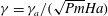 ${\it\gamma}={\it\gamma}_{a}/(\sqrt{\mathit{Pm}}\mathit{Ha})$
. Neglecting all of the terms related to viscous and magnetic diffusion, we obtain a second-order Master equation for
${\it\gamma}={\it\gamma}_{a}/(\sqrt{\mathit{Pm}}\mathit{Ha})$
. Neglecting all of the terms related to viscous and magnetic diffusion, we obtain a second-order Master equation for
 $q$
. Up to some rescaling of the amplitudes, the fields can be obtained from (4.11). Only one radial wavenumber
$q$
. Up to some rescaling of the amplitudes, the fields can be obtained from (4.11). Only one radial wavenumber
 $k$
appears in the radial structure and the characteristic polynomial is linear
$k$
appears in the radial structure and the characteristic polynomial is linear
 $$\begin{eqnarray}Q(z)=[{\it\gamma}^{2}+m^{2}]^{2}z-4m^{2}l^{2},\end{eqnarray}$$
where we recall that
 $z=k^{2}+l^{2}$
. The corresponding growth rate in Alfvén’s units is henceforth denoted by
$z=k^{2}+l^{2}$
. The corresponding growth rate in Alfvén’s units is henceforth denoted by
 ${\it\gamma}_{a,ideal}$
. The wavenumber
${\it\gamma}_{a,ideal}$
. The wavenumber
 $k$
is such that the no-penetration boundary condition is satisfied on the lateral boundary
$k$
is such that the no-penetration boundary condition is satisfied on the lateral boundary
 $r=1$
:
$r=1$
:
 $$\begin{eqnarray}u_{r}|_{1^{-}}=0,\end{eqnarray}$$
which requires that
 $k$
solves
$k$
solves
 $$\begin{eqnarray}\left(1-\sqrt{1+\frac{k^{2}}{l^{2}}}\right)\text{J}_{m+1}(k)+\left(1+\sqrt{1+\frac{k^{2}}{l^{2}}}\right)\text{J}_{m-1}(k)=0.\end{eqnarray}$$
This equation has only real solutions, and they can be easily computed numerically. No boundary/transmission condition on the magnetic field can be enforced, which means that we cannot differentiate configurations I and II. The growth rate is found by computing the single root of
 $Q$
, see (4.21):
$Q$
, see (4.21):
 $$\begin{eqnarray}{\it\gamma}_{a,ideal}=\sqrt{\frac{2|m|}{\displaystyle \sqrt{1+\frac{k^{2}}{l^{2}}}}-m^{2}}.\end{eqnarray}$$
Since the wavenumber
 $k$
is real, we deduce that only modes
$k$
is real, we deduce that only modes
 $m=\pm 1$
can be unstable (to have a positive value under the square root). It follows that instability is possible only if
$m=\pm 1$
can be unstable (to have a positive value under the square root). It follows that instability is possible only if
 $|k|/|l|<\sqrt{3}$
.
$|k|/|l|<\sqrt{3}$
.
4.3. Linear stability: results and comparison
In agreement with the numerical simulations performed in § 3, and other previously published results (see e.g. Tayler Reference Tayler1957 and Rüdiger et al.
Reference Rüdiger, Schultz and Gellert2011, Reference Rüdiger, Gellert, Schultz, Strassmeier, Stefani, Gundrum, Seilmayer and Gerbeth2012), we find that only modes with azimuthal wavenumbers such that
 $|m|=1$
are unstable and the corresponding growth rates are real above some critical number
$|m|=1$
are unstable and the corresponding growth rates are real above some critical number
 $\mathit{Ha}_{c}$
. The objective of this section is threefold: first we discuss the cases studied in § 3 and compare the numerical results with our theoretical estimates; then we explore the range of the parameters
$\mathit{Ha}_{c}$
. The objective of this section is threefold: first we discuss the cases studied in § 3 and compare the numerical results with our theoretical estimates; then we explore the range of the parameters
 $\mathit{Pm},\mathit{Ha}$
; finally we consider the non-viscous limits. The numerical growth rates obtained with SFEMaNS are scaled in Alfvén’s time unit. They are converted in the present units by using the formula
$\mathit{Pm},\mathit{Ha}$
; finally we consider the non-viscous limits. The numerical growth rates obtained with SFEMaNS are scaled in Alfvén’s time unit. They are converted in the present units by using the formula
 ${\it\gamma}={\it\gamma}_{a}/(\sqrt{\mathit{Pm}}\mathit{Ha})$
.
${\it\gamma}={\it\gamma}_{a}/(\sqrt{\mathit{Pm}}\mathit{Ha})$
.
4.3.1. Case
$h=2$
,
$\mathit{Ha}=24$
,
$\mathit{Pm}=10^{-2}$


We start with configuration II. Assuming periodicity in the vertical direction with period
 $h$
, we must have
$h$
, we must have
 $l=2{\rm\pi}n/h$
with integer
$l=2{\rm\pi}n/h$
with integer
 $n$
. The fundamental mode with one wavelength along
$n$
. The fundamental mode with one wavelength along
 $z$
is then
$z$
is then
 $l=\pm {\rm\pi}$
. The mode
$l=\pm {\rm\pi}$
. The mode
 $m=1$
and
$m=1$
and
 $l={\rm\pi}$
is unstable, and the growth rate given by the linear stability analysis is
$l={\rm\pi}$
is unstable, and the growth rate given by the linear stability analysis is
 ${\it\gamma}=7.805\times 10^{-3}$
. This corresponds very well to the value
${\it\gamma}=7.805\times 10^{-3}$
. This corresponds very well to the value
 $7.804\times 10^{-3}$
estimated with SFEMaNS (
$7.804\times 10^{-3}$
estimated with SFEMaNS (
 ${\it\gamma}_{a}=1.87\times 10^{-2}$
in table 1). The spatial structure of this mode is shown in figure 10. The amplitudes are normalized so that
${\it\gamma}_{a}=1.87\times 10^{-2}$
in table 1). The spatial structure of this mode is shown in figure 10. The amplitudes are normalized so that
 $\max (|u_{r}|,|u_{{\it\theta}}|,|u_{z}|)=1$
. Note that the velocity and the magnetic fields are in quadrature, and the radial component of each field is in quadrature with the azimuthal and axial components.
$\max (|u_{r}|,|u_{{\it\theta}}|,|u_{z}|)=1$
. Note that the velocity and the magnetic fields are in quadrature, and the radial component of each field is in quadrature with the azimuthal and axial components.

Figure 10. Radial structure of the unstable Tayler mode in configuration II:
 $m=1$
,
$m=1$
,
 $l={\rm\pi}$
,
$l={\rm\pi}$
,
 $\mathit{Ha}=24$
and
$\mathit{Ha}=24$
and
 $\mathit{Pm}=10^{-2}$
.
$\mathit{Pm}=10^{-2}$
.
Since the growth rates are exactly the same for all four combinations of
 $m=\pm 1$
and
$m=\pm 1$
and
 $l=\pm {\rm\pi}$
, a Tayler mode is a real-valued superposition of these four complex fundamental modes and can be represented as follows:
$l=\pm {\rm\pi}$
, a Tayler mode is a real-valued superposition of these four complex fundamental modes and can be represented as follows:
 $$\begin{eqnarray}\left[\begin{array}{@{}c@{}}u_{r}\\ u_{{\it\theta}}\\ u_{z}\\ b_{r}\\ b_{{\it\theta}}\\ b_{z}\end{array}\right]=\text{Re}\left(A_{+}\left[\begin{array}{@{}c@{}}V_{r}(r)\\ \text{i}V_{{\it\theta}}(r)\\ -\text{i}V_{z}(r)\\ \text{i}C_{r}(r)\\ -C_{{\it\theta}}(r)\\ C_{z}(r)\end{array}\right]\text{e}^{\text{i}({\it\theta}+lz)}+A_{-}\left[\begin{array}{@{}c@{}}V_{r}(r)\\ -\text{i}V_{{\it\theta}}(r)\\ -\text{i}V_{z}(r)\\ -\text{i}C_{r}(r)\\ -C_{{\it\theta}}(r)\\ -C_{z}(r)\end{array}\right]\text{e}^{\text{i}(-{\it\theta}+lz)}\right)\text{e}^{{\it\gamma}t}.\end{eqnarray}$$
We can now understand why the modes come in different classes as observed with SFEMaNS. If one of the amplitudes
 $A_{+}$
or
$A_{+}$
or
 $A_{-}$
is zero, we have an helical mode as in figure 2(a,b), with either left-hand or right-hand polarizations. These solutions are the modes labelled
$A_{-}$
is zero, we have an helical mode as in figure 2(a,b), with either left-hand or right-hand polarizations. These solutions are the modes labelled
 $\boldsymbol{L}$
and
$\boldsymbol{L}$
and
 $\boldsymbol{R}$
in Bonanno et al. (Reference Bonanno, Brandenburg, Del Sordo and Mitra2012). When
$\boldsymbol{R}$
in Bonanno et al. (Reference Bonanno, Brandenburg, Del Sordo and Mitra2012). When
 $|A_{+}|=|A_{-}|$
, we obtain the modes of figure 2(c,d). In all of the other cases the modes are superposed; this is not observed in the simulations because of the adopted initial conditions.
$|A_{+}|=|A_{-}|$
, we obtain the modes of figure 2(c,d). In all of the other cases the modes are superposed; this is not observed in the simulations because of the adopted initial conditions.
The choice of amplitudes is further limited in the finite cylinder with the stress-free boundary condition. It is possible to construct superpositions such that
 $u_{z}$
,
$u_{z}$
,
 $\partial _{z}u_{\pm }$
,
$\partial _{z}u_{\pm }$
,
 $b_{z}$
,
$b_{z}$
,
 $j_{\pm }\sim \sin (lz)$
along
$j_{\pm }\sim \sin (lz)$
along
 $z$
, so that the stress-free TB-BC boundary conditions (3.6) can be satisfied with the choice
$z$
, so that the stress-free TB-BC boundary conditions (3.6) can be satisfied with the choice
 $l=n{\rm\pi}/h$
and
$l=n{\rm\pi}/h$
and
 $n\in \mathbb{N}$
, only if
$n\in \mathbb{N}$
, only if
 $A_{+}=A_{-}^{\ast }$
. Helical modes are thus excluded by the stress-free boundary condition in agreement with the numerical observations in § 3.2.2, i.e. helical modes do not spontaneously emerge as they do in the setting studied in Bonanno et al. (Reference Bonanno, Brandenburg, Del Sordo and Mitra2012). Note also that with stress-free TB-BC the fundamental wavenumber is no longer
$A_{+}=A_{-}^{\ast }$
. Helical modes are thus excluded by the stress-free boundary condition in agreement with the numerical observations in § 3.2.2, i.e. helical modes do not spontaneously emerge as they do in the setting studied in Bonanno et al. (Reference Bonanno, Brandenburg, Del Sordo and Mitra2012). Note also that with stress-free TB-BC the fundamental wavenumber is no longer
 ${\rm\pi}$
but
${\rm\pi}$
but
 ${\rm\pi}/2$
in the cylinder
${\rm\pi}/2$
in the cylinder
 $h=2$
. This is in agreement with the fact that two competing modes (SF-one and SF-half) were found for this configuration (see figure 6). The linear stability analysis gives a second unstable mode with
$h=2$
. This is in agreement with the fact that two competing modes (SF-one and SF-half) were found for this configuration (see figure 6). The linear stability analysis gives a second unstable mode with
 $l={\rm\pi}/2$
, and the corresponding growth rate
$l={\rm\pi}/2$
, and the corresponding growth rate
 ${\it\gamma}=2.289\times 10^{-3}$
at
${\it\gamma}=2.289\times 10^{-3}$
at
 $\mathit{Ha}=24$
is three times smaller than that of the SF-one mode. Again this agrees very well with the value
$\mathit{Ha}=24$
is three times smaller than that of the SF-one mode. Again this agrees very well with the value
 $2.312\times 10^{-3}$
evaluated numerically (
$2.312\times 10^{-3}$
evaluated numerically (
 ${\it\gamma}_{a}=5.55\times 10^{-3}$
in the rightmost column of table 4). The linear stability analysis explains well the presence of the SF-half mode, but it does not explain why this mode wins the competition over the SF-one mode in the nonlinear regime.
${\it\gamma}_{a}=5.55\times 10^{-3}$
in the rightmost column of table 4). The linear stability analysis explains well the presence of the SF-half mode, but it does not explain why this mode wins the competition over the SF-one mode in the nonlinear regime.

Figure 11. Critical Hartmann number
 $\mathit{Ha}_{c}$
versus wavenumber
$\mathit{Ha}_{c}$
versus wavenumber
 $l$
.
$l$
.
4.3.2. Variation of
$\mathit{Ha}_{c}$
with
$l$


The critical Hartmann number for the onset of the Tayler instability,
 $\mathit{Ha}_{c}$
, is independent of the Prandtl number; it depends only on the vertical wavenumber
$\mathit{Ha}_{c}$
, is independent of the Prandtl number; it depends only on the vertical wavenumber
 $l$
. We have calculated this number for both configurations I and II over a large interval for
$l$
. We have calculated this number for both configurations I and II over a large interval for
 $l$
; the results are displayed in figure 11. We observe that the behaviour of
$l$
; the results are displayed in figure 11. We observe that the behaviour of
 $\mathit{Ha}_{c}$
with respect to
$\mathit{Ha}_{c}$
with respect to
 $l$
is similar in configurations I and II. There is a lower limit under which the Tayler instability cannot exist. The thresholds for both configurations I and II become identical in the limit
$l$
is similar in configurations I and II. There is a lower limit under which the Tayler instability cannot exist. The thresholds for both configurations I and II become identical in the limit
 $l\rightarrow +\infty$
; this is a consequence of the fact that the exterior magnetic field quickly decays away from the cylinder as
$l\rightarrow +\infty$
; this is a consequence of the fact that the exterior magnetic field quickly decays away from the cylinder as
 $l$
increases. The pairs
$l$
increases. The pairs
 $(l_{\ast },\mathit{Ha}_{c,\ast })$
corresponding to the lowest threshold are
$(l_{\ast },\mathit{Ha}_{c,\ast })$
corresponding to the lowest threshold are
 $$\begin{eqnarray}\left.\begin{array}{@{}l@{}}\text{I}~(\blacksquare ):~l_{\ast }=2.483,\quad \mathit{Ha}_{c,\ast }=21.092,\\ \text{II}~(\bullet ):~l_{\ast }=2.271,\quad \mathit{Ha}_{c,\ast }=19.296.\end{array}\right\}\end{eqnarray}$$
We have investigated numerically the optimal cylinder with height
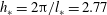 $h_{\ast }=2{\rm\pi}/l_{\ast }=2.77$
and we have obtained
$h_{\ast }=2{\rm\pi}/l_{\ast }=2.77$
and we have obtained
 $\mathit{Ha}_{c}\approx 19.4$
in configuration II, see § 3.3. These results are also in good agreement with the result
$\mathit{Ha}_{c}\approx 19.4$
in configuration II, see § 3.3. These results are also in good agreement with the result
 $\mathit{Ha}_{c,\ast }\approx 22$
found in Rüdiger et al. (Reference Rüdiger, Gellert, Schultz, Strassmeier, Stefani, Gundrum, Seilmayer and Gerbeth2012) for an infinite cylinder with insulating walls (i.e. configuration I).
$\mathit{Ha}_{c,\ast }\approx 22$
found in Rüdiger et al. (Reference Rüdiger, Gellert, Schultz, Strassmeier, Stefani, Gundrum, Seilmayer and Gerbeth2012) for an infinite cylinder with insulating walls (i.e. configuration I).
4.3.3. Variation of
${\it\gamma}$
and
${\it\gamma}_{qs}$
with
$\mathit{Ha}$


Since most of the numerical simulations have been done with the aspect ratio
 $h=2$
, we now fix
$h=2$
, we now fix
 $l={\rm\pi}$
and compute the theoretical values for the growth rates in both configurations I and II for a large range of parameters
$l={\rm\pi}$
and compute the theoretical values for the growth rates in both configurations I and II for a large range of parameters
 $\mathit{Pm}$
,
$\mathit{Pm}$
,
 $\mathit{Ha}$
. The results are gathered in figure 12: figure 12(a) gives the growth rate
$\mathit{Ha}$
. The results are gathered in figure 12: figure 12(a) gives the growth rate
 ${\it\gamma}$
as a function of
${\it\gamma}$
as a function of
 $\mathit{Ha}$
, for various values of
$\mathit{Ha}$
, for various values of
 $\mathit{Pm}$
; figure 12(b) gives the same results in rescaled units,
$\mathit{Pm}$
; figure 12(b) gives the same results in rescaled units,
 ${\it\gamma}_{a}=\mathit{Ha}\sqrt{\mathit{Pm}}{\it\gamma}$
. Comparing the dashed lines (configuration I) and the solid lines (configuration II), we observe that both configurations behave very similarly for all of the values of
${\it\gamma}_{a}=\mathit{Ha}\sqrt{\mathit{Pm}}{\it\gamma}$
. Comparing the dashed lines (configuration I) and the solid lines (configuration II), we observe that both configurations behave very similarly for all of the values of
 $\mathit{Pm}$
and
$\mathit{Pm}$
and
 $\mathit{Ha}$
explored. This observation further supports the idea that the exact nature of the magnetic boundary condition on the cylindrical sidewall is not so important for the Tayler instability. The circles indicate the values measured from the numerical simulations in configuration II. We observe a very good agreement between the numerics and the linear stability theory, which cross-validates both approaches. The theoretical value for the threshold is
$\mathit{Ha}$
explored. This observation further supports the idea that the exact nature of the magnetic boundary condition on the cylindrical sidewall is not so important for the Tayler instability. The circles indicate the values measured from the numerical simulations in configuration II. We observe a very good agreement between the numerics and the linear stability theory, which cross-validates both approaches. The theoretical value for the threshold is
 $\mathit{Ha}_{c}=21.58$
in configuration II. This value is very close to the estimate
$\mathit{Ha}_{c}=21.58$
in configuration II. This value is very close to the estimate
 $\mathit{Ha}_{c}\approx 21.7$
obtained numerically with SFEMaNS (see table 1).
$\mathit{Ha}_{c}\approx 21.7$
obtained numerically with SFEMaNS (see table 1).

Figure 12. Growth rates versus
 $\mathit{Ha}$
for various
$\mathit{Ha}$
for various
 $\mathit{Pm}$
as indicated in the figure using different units: (a) growth rate
$\mathit{Pm}$
as indicated in the figure using different units: (a) growth rate
 ${\it\gamma}$
in units
${\it\gamma}$
in units
 $({\it\sigma}B_{0}^{2})/{\it\rho}$
; (b) growth rate
$({\it\sigma}B_{0}^{2})/{\it\rho}$
; (b) growth rate
 ${\it\gamma}_{a}$
in units
${\it\gamma}_{a}$
in units
 $(\sqrt{{\it\rho}{\it\mu}_{0}}R)/B_{0}$
. Dashed lines: configuration I. Full lines: configuration II. Markers (○): growth rates from SFEMaNS. Horizontal lines: non-viscous QS asymptotes in (a), non-viscous non-diffusive asymptote in (b).
$(\sqrt{{\it\rho}{\it\mu}_{0}}R)/B_{0}$
. Dashed lines: configuration I. Full lines: configuration II. Markers (○): growth rates from SFEMaNS. Horizontal lines: non-viscous QS asymptotes in (a), non-viscous non-diffusive asymptote in (b).
We now discuss the behaviour of the theoretical curves in figure 12(a) as
 $\mathit{Ha}$
goes from
$\mathit{Ha}$
goes from
 $\mathit{Ha}_{c}$
to
$\mathit{Ha}_{c}$
to
 $+\infty$
. The two curves labelled
$+\infty$
. The two curves labelled
 ${\it\gamma}_{qs}$
correspond to the QS limit with
${\it\gamma}_{qs}$
correspond to the QS limit with
 $\mathit{Pm}=0$
. The graph of
$\mathit{Pm}=0$
. The graph of
 ${\it\gamma}_{qs}$
monotonically increases with
${\it\gamma}_{qs}$
monotonically increases with
 $\mathit{Ha}$
and converges to the non-viscous horizontal asymptote as
$\mathit{Ha}$
and converges to the non-viscous horizontal asymptote as
 $\mathit{Ha}\rightarrow +\infty$
. The approximate values for the non-viscous limit are
$\mathit{Ha}\rightarrow +\infty$
. The approximate values for the non-viscous limit are
 ${\it\gamma}_{nvqs}=0.0409$
in configuration I and
${\it\gamma}_{nvqs}=0.0409$
in configuration I and
 ${\it\gamma}_{nvqs}=0.0459$
in configuration II. These values closely match the value given by Rüdiger et al. (Reference Rüdiger, Gellert, Schultz, Strassmeier, Stefani, Gundrum, Seilmayer and Gerbeth2012, equation (7)), who studied configuration I and found
${\it\gamma}_{nvqs}=0.0459$
in configuration II. These values closely match the value given by Rüdiger et al. (Reference Rüdiger, Gellert, Schultz, Strassmeier, Stefani, Gundrum, Seilmayer and Gerbeth2012, equation (7)), who studied configuration I and found
 ${\it\Gamma}\simeq 0.04$
.
${\it\Gamma}\simeq 0.04$
.
We now consider the effect of
 $\mathit{Pm}$
. When
$\mathit{Pm}$
. When
 $\mathit{Pm}\ll 1$
, the graph of
$\mathit{Pm}\ll 1$
, the graph of
 ${\it\gamma}$
follows that of the QS limit over some interval of width depending on
${\it\gamma}$
follows that of the QS limit over some interval of width depending on
 $\mathit{Pm}$
, and it eventually bends down and separates from the QS limit as
$\mathit{Pm}$
, and it eventually bends down and separates from the QS limit as
 $\mathit{Ha}$
increases. Then the graph of
$\mathit{Ha}$
increases. Then the graph of
 ${\it\gamma}$
reaches a maximum at a transitional Hartmann number we note
${\it\gamma}$
reaches a maximum at a transitional Hartmann number we note
 $\mathit{Ha}_{tr}(\mathit{Pm})$
and which value depends on
$\mathit{Ha}_{tr}(\mathit{Pm})$
and which value depends on
 $\mathit{Pm}$
. This behaviour is due to the term
$\mathit{Pm}$
. This behaviour is due to the term
 $\mathit{Pm}\mathit{Ha}^{2}\partial _{t}\boldsymbol{b}$
that is neglected in the QS regime. If
$\mathit{Pm}\mathit{Ha}^{2}\partial _{t}\boldsymbol{b}$
that is neglected in the QS regime. If
 $\mathit{Pm}\neq 0$
, this term eventually gains weight in the induction equation when
$\mathit{Pm}\neq 0$
, this term eventually gains weight in the induction equation when
 $\mathit{Ha}$
is large enough. It has been possible to go beyond the maximum for
$\mathit{Ha}$
is large enough. It has been possible to go beyond the maximum for
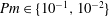 $\mathit{Pm}\in \{10^{-1},10^{-2}\}$
, and we observe that
$\mathit{Pm}\in \{10^{-1},10^{-2}\}$
, and we observe that
 ${\it\gamma}\rightarrow 0$
when
${\it\gamma}\rightarrow 0$
when
 $\mathit{Ha}\rightarrow +\infty$
. In this limit, the growth rate is better expressed in Alfvén’s time units
$\mathit{Ha}\rightarrow +\infty$
. In this limit, the growth rate is better expressed in Alfvén’s time units
 ${\it\gamma}_{a}={\it\gamma}\sqrt{\mathit{Pm}}\mathit{Ha}$
as shown in figure 12(b). With this new scaling, all of the graphs appear in reversed order and we see that they all seem to converge towards the ideal MHD horizontal asymptote, here found at
${\it\gamma}_{a}={\it\gamma}\sqrt{\mathit{Pm}}\mathit{Ha}$
as shown in figure 12(b). With this new scaling, all of the graphs appear in reversed order and we see that they all seem to converge towards the ideal MHD horizontal asymptote, here found at
 ${\it\gamma}_{a,ideal}=0.7804$
.
${\it\gamma}_{a,ideal}=0.7804$
.
The quantity labelled
 $\mathit{Ha}_{tr}$
is informative in the sense that the Tayler instability is of QS nature over the interval
$\mathit{Ha}_{tr}$
is informative in the sense that the Tayler instability is of QS nature over the interval
 $[\mathit{Ha}_{c},\mathit{Ha}_{tr}(\mathit{Pm})]$
. In other words, as long as we keep
$[\mathit{Ha}_{c},\mathit{Ha}_{tr}(\mathit{Pm})]$
. In other words, as long as we keep
 $\mathit{Ha}<\mathit{Ha}_{tr}$
, numerical simulations done with
$\mathit{Ha}<\mathit{Ha}_{tr}$
, numerical simulations done with
 $\mathit{Pm}\in [10^{-3},10^{-2}]$
will give rise to Tayler instabilities that are very similar in structure to those that would have been obtained by using
$\mathit{Pm}\in [10^{-3},10^{-2}]$
will give rise to Tayler instabilities that are very similar in structure to those that would have been obtained by using
 $\mathit{Pm}=10^{-6}$
, which is a value of the Prandtl number that is more representative of liquid metals. Obtaining a precise behaviour of
$\mathit{Pm}=10^{-6}$
, which is a value of the Prandtl number that is more representative of liquid metals. Obtaining a precise behaviour of
 $\mathit{Ha}_{tr}$
as a function of
$\mathit{Ha}_{tr}$
as a function of
 $\mathit{Pm}$
is thus useful to estimate when we can obtain the correct physics at a smaller computational cost using SFEMaNS. We have computed
$\mathit{Pm}$
is thus useful to estimate when we can obtain the correct physics at a smaller computational cost using SFEMaNS. We have computed
 $\mathit{Ha}_{tr}$
for various values of
$\mathit{Ha}_{tr}$
for various values of
 $\mathit{Pm}\in [10^{-4},1]$
; the quantity
$\mathit{Pm}\in [10^{-4},1]$
; the quantity
 $\mathit{Ha}_{tr}-\mathit{Ha}_{c}$
is shown in figure 13 as a function of
$\mathit{Ha}_{tr}-\mathit{Ha}_{c}$
is shown in figure 13 as a function of
 $\mathit{Pm}$
. We observe a scaling law
$\mathit{Pm}$
. We observe a scaling law
 $$\begin{eqnarray}\mathit{Ha}_{tr}-\mathit{Ha}_{c}\sim \mathit{Pm}^{-3\pm 0.1},\end{eqnarray}$$
for small values of
 $\mathit{Pm}$
. We have used this relation to extrapolate the curve in the range
$\mathit{Pm}$
. We have used this relation to extrapolate the curve in the range
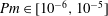 $\mathit{Pm}\in [10^{-6},10^{-5}]$
which is typical for liquid metals. The graph in figure 13 can be interpreted as a phase diagram in some sense: under the curve the Tayler instability is of QS nature; above, the Tayler instability has the structure of the ideal MHD limit. This tells us that the Tayler instability in liquid metal columns can be modelled using the QS approach up to very high Hartmann numbers. Numerical values of
$\mathit{Pm}\in [10^{-6},10^{-5}]$
which is typical for liquid metals. The graph in figure 13 can be interpreted as a phase diagram in some sense: under the curve the Tayler instability is of QS nature; above, the Tayler instability has the structure of the ideal MHD limit. This tells us that the Tayler instability in liquid metal columns can be modelled using the QS approach up to very high Hartmann numbers. Numerical values of
 $\mathit{Ha}_{tr}$
are given in table 5.
$\mathit{Ha}_{tr}$
are given in table 5.

Figure 13. Transitional Hartmann number
 $\mathit{Ha}_{tr}$
versus
$\mathit{Ha}_{tr}$
versus
 $\mathit{Pm}$
; the QS approximation applies when
$\mathit{Pm}$
; the QS approximation applies when
 $\mathit{Ha}<\mathit{Ha}_{tr}$
; the ideal MHD limit becomes valid when
$\mathit{Ha}<\mathit{Ha}_{tr}$
; the ideal MHD limit becomes valid when
 $\mathit{Ha}\gg \mathit{Ha}_{tr}$
.
$\mathit{Ha}\gg \mathit{Ha}_{tr}$
.
4.3.4. Non-viscous limits:
${\it\gamma}_{nvqs}$
and
${\it\gamma}_{a,ideal}$
as a function of
$l$


Figure 12 illustrates well the importance of the non-viscous asymptotes
 ${\it\gamma}_{nvqs}$
and
${\it\gamma}_{nvqs}$
and
 ${\it\gamma}_{a,ideal}$
as
${\it\gamma}_{a,ideal}$
as
 $\mathit{Ha}\rightarrow +\infty$
for the particular value
$\mathit{Ha}\rightarrow +\infty$
for the particular value
 $l={\rm\pi}$
. We now calculate the non-viscous growth rates
$l={\rm\pi}$
. We now calculate the non-viscous growth rates
 ${\it\gamma}_{nvqs}$
and
${\it\gamma}_{nvqs}$
and
 ${\it\gamma}_{a,ideal}$
over a large interval of wavenumbers
${\it\gamma}_{a,ideal}$
over a large interval of wavenumbers
 $l$
. The results are shown in figure 14(a) for
$l$
. The results are shown in figure 14(a) for
 ${\it\gamma}_{nvqs}$
and figure 14(b) for
${\it\gamma}_{nvqs}$
and figure 14(b) for
 ${\it\gamma}_{a,ideal}$
; the computations are done for both configurations I and II using (4.23) and (4.24).
${\it\gamma}_{a,ideal}$
; the computations are done for both configurations I and II using (4.23) and (4.24).

Figure 14. Growth rates in non-viscous limits versus wavenumber
 $l$
. (a) Non-viscous QS limit for configurations I (dashed line) and II (solid line). (b) Ideal MHD limit. Each branch is associated with one, three or five radial structures as shown in the inset.
$l$
. (a) Non-viscous QS limit for configurations I (dashed line) and II (solid line). (b) Ideal MHD limit. Each branch is associated with one, three or five radial structures as shown in the inset.
Table 5. Transitional Hartmann number
 $\mathit{Ha}_{tr}$
number indicating change in regime: the QS approximation holds when
$\mathit{Ha}_{tr}$
number indicating change in regime: the QS approximation holds when
 $\mathit{Ha}<\mathit{Ha}_{tr}$
.
$\mathit{Ha}<\mathit{Ha}_{tr}$
.

Figure 14(a) reveals three branches in the NVQS limit, each corresponding to an unstable mode. The spatial structure of these modes is shown in the inset between the two panels. The first, second and third Tayler modes are composed of one, three and five rolls along the radial direction, respectively. We do not focus on modes with more than one roll in the radial direction in this paper, since the one-roll pattern is always dominant in the viscous regime. We observe also that each mode has a negative growth rate beneath a minimal wavenumber
 $l$
. This observation explains why the threshold
$l$
. This observation explains why the threshold
 $\mathit{Ha}_{c}$
grows to infinity in figure 11 when
$\mathit{Ha}_{c}$
grows to infinity in figure 11 when
 $l\rightarrow 0$
.
$l\rightarrow 0$
.
In the ideal MHD limit, figure 14(b) shows again three branches for
 ${\it\gamma}_{a,ideal}$
, each of these branches corresponding to a Tayler mode with one, three and five rolls along the radial direction.
${\it\gamma}_{a,ideal}$
, each of these branches corresponding to a Tayler mode with one, three and five rolls along the radial direction.
4.3.5. Conclusions of the linear analysis
Close to threshold and for small Prandtl numbers, the Tayler instability is QS in nature; more precisely, in the region
 $\mathit{Ha}_{c}\leqslant \mathit{Ha}<\mathit{Ha}_{tr}(\mathit{Pm})$
,
$\mathit{Ha}_{c}\leqslant \mathit{Ha}<\mathit{Ha}_{tr}(\mathit{Pm})$
,
 $\mathit{Pm}\ll 1$
, the dimensional growth rate scales like
$\mathit{Pm}\ll 1$
, the dimensional growth rate scales like
 $$\begin{eqnarray}{\it\gamma}_{qs}(\mathit{Ha})\frac{{\it\sigma}B_{0}^{2}}{{\it\rho}}={\it\gamma}_{qs}(\mathit{Ha})\mathit{Ha}^{2}\frac{{\it\nu}}{R^{2}}={\it\gamma}_{qs}(\mathit{Ha})\mathit{Ha}\sqrt{\mathit{Pm}}\frac{B_{0}}{\sqrt{{\it\rho}{\it\mu}_{0}}R},\end{eqnarray}$$
where the function
 ${\it\gamma}_{qs}(\mathit{Ha})$
is the QS growth rate; it is concave down, increases monotonically and converges to the non-viscous horizontal asymptote as
${\it\gamma}_{qs}(\mathit{Ha})$
is the QS growth rate; it is concave down, increases monotonically and converges to the non-viscous horizontal asymptote as
 $\mathit{Ha}\rightarrow +\infty$
. For the reader’s convenience, we have written (4.28) using the time unit,
$\mathit{Ha}\rightarrow +\infty$
. For the reader’s convenience, we have written (4.28) using the time unit,
 ${\it\rho}/{\it\sigma}B_{0}^{2}$
, the viscous time unit,
${\it\rho}/{\it\sigma}B_{0}^{2}$
, the viscous time unit,
 $R^{2}/{\it\nu}$
, and Alfvén’s time unit,
$R^{2}/{\it\nu}$
, and Alfvén’s time unit,
 $\sqrt{{\it\rho}{\it\mu}_{0}}R/B_{0}$
. Then, in addition to the Alfvén scaling
$\sqrt{{\it\rho}{\it\mu}_{0}}R/B_{0}$
. Then, in addition to the Alfvén scaling
 $\mathit{Ha}\sqrt{\mathit{Pm}}$
, we recover the
$\mathit{Ha}\sqrt{\mathit{Pm}}$
, we recover the
 $\mathit{Ha}^{2}$
scaling identified in Rüdiger & Schultz (Reference Rüdiger and Schultz2010) and Rüdiger et al. (Reference Rüdiger, Schultz and Gellert2011, Reference Rüdiger, Gellert, Schultz, Strassmeier, Stefani, Gundrum, Seilmayer and Gerbeth2012). These expressions show that the time unit
$\mathit{Ha}^{2}$
scaling identified in Rüdiger & Schultz (Reference Rüdiger and Schultz2010) and Rüdiger et al. (Reference Rüdiger, Schultz and Gellert2011, Reference Rüdiger, Gellert, Schultz, Strassmeier, Stefani, Gundrum, Seilmayer and Gerbeth2012). These expressions show that the time unit
 ${\it\rho}/{\it\sigma}B_{0}^{2}$
is well adapted to describe the QS regime.
${\it\rho}/{\it\sigma}B_{0}^{2}$
is well adapted to describe the QS regime.
Considering that the magnetic Prandtl number in liquid metals is usually very small, say in the range
 $[10^{-8},10^{-5}]$
, and that it is very difficult to reach very high Hartmann numbers in experiments with liquid metals, we conclude that the QS regime is relevant for the analysis of the Tayler instability in LMBs. Numerical codes that adopt the QS approximation as in Weber et al. (Reference Weber, Galindo, Stefani, Weier and Wondrak2013) are thus well adapted to capture the dynamics in these systems in the range
$[10^{-8},10^{-5}]$
, and that it is very difficult to reach very high Hartmann numbers in experiments with liquid metals, we conclude that the QS regime is relevant for the analysis of the Tayler instability in LMBs. Numerical codes that adopt the QS approximation as in Weber et al. (Reference Weber, Galindo, Stefani, Weier and Wondrak2013) are thus well adapted to capture the dynamics in these systems in the range
 $0\leqslant \mathit{Ha}\lesssim 10^{3}$
(see table 5), since as argued in Weber et al. (Reference Weber, Galindo, Stefani, Weier and Wondrak2013) adopting a time-marching strategy to solve the induction equation in this regime can be time consuming due to severe time step restrictions. Still this does not exclude that other numerical codes such as SFEMaNS, which are based on time-stepping, cannot track the Tayler instability in the QS limit. Actually, table 5 shows that the QS behaviour is well captured when
$0\leqslant \mathit{Ha}\lesssim 10^{3}$
(see table 5), since as argued in Weber et al. (Reference Weber, Galindo, Stefani, Weier and Wondrak2013) adopting a time-marching strategy to solve the induction equation in this regime can be time consuming due to severe time step restrictions. Still this does not exclude that other numerical codes such as SFEMaNS, which are based on time-stepping, cannot track the Tayler instability in the QS limit. Actually, table 5 shows that the QS behaviour is well captured when
 $0\leqslant \mathit{Ha}\lesssim \mathit{Ha}_{tr}(\mathit{Pm})$
; this is the case for Hartmann numbers in the range
$0\leqslant \mathit{Ha}\lesssim \mathit{Ha}_{tr}(\mathit{Pm})$
; this is the case for Hartmann numbers in the range
 $0\leqslant \mathit{Ha}\lesssim 10^{2}$
when
$0\leqslant \mathit{Ha}\lesssim 10^{2}$
when
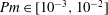 $\mathit{Pm}\in [10^{-3},10^{-2}]$
. This range is well within reach of time-stepping codes.
$\mathit{Pm}\in [10^{-3},10^{-2}]$
. This range is well within reach of time-stepping codes.
4.4. Nonlinear regime
The linear stability analysis is valid only in the infinitesimal limit, i.e. it cannot predict the nonlinear saturation level of instabilities. The purpose of this section is to use a weakly nonlinear equilibrium theory to estimate the nonlinear amplitude of the Tayler instability in the QS limit. We do not perform a detailed analysis but instead sketch a plausible scenario leading to a particular scaling of the amplitude of the flow.
To simplify the notation, we introduce the state vector
 $\boldsymbol{X}=[\boldsymbol{u},\boldsymbol{b},q]^{\text{T}}$
and rewrite the nonlinear perturbation problem (4.2) as
$\boldsymbol{X}=[\boldsymbol{u},\boldsymbol{b},q]^{\text{T}}$
and rewrite the nonlinear perturbation problem (4.2) as
 $$\begin{eqnarray}\partial _{t}\mathscr{J}\boldsymbol{X}+\mathscr{L}\boldsymbol{X}=\mathscr{N}(\boldsymbol{X},\boldsymbol{X}).\end{eqnarray}$$
The QS limit is obtained by neglecting all of the terms that are proportional to
 $\mathit{Pm}\mathit{Ha}^{2}\ll 1$
. We then have
$\mathit{Pm}\mathit{Ha}^{2}\ll 1$
. We then have
 $\mathscr{J}=\text{diag}(1,1,1,0,0,0,0)$
, and
$\mathscr{J}=\text{diag}(1,1,1,0,0,0,0)$
, and
 $\mathscr{L}$
is a linear differential operator involving only spatial derivatives. The nonlinear operator reduces to
$\mathscr{L}$
is a linear differential operator involving only spatial derivatives. The nonlinear operator reduces to
 $\mathscr{N}(\boldsymbol{X},\boldsymbol{X})=(-(\boldsymbol{u}\boldsymbol{\cdot }\boldsymbol{{\rm\nabla}})\boldsymbol{u},\mathbf{0},0)$
. Let us then first return to the linear stability analysis problem. The unstable Tayler mode computed in the previous section, say
$\mathscr{N}(\boldsymbol{X},\boldsymbol{X})=(-(\boldsymbol{u}\boldsymbol{\cdot }\boldsymbol{{\rm\nabla}})\boldsymbol{u},\mathbf{0},0)$
. Let us then first return to the linear stability analysis problem. The unstable Tayler mode computed in the previous section, say
 $\boldsymbol{X}_{T}=\boldsymbol{Y}_{T}(\boldsymbol{x})\text{e}^{{\it\gamma}_{qs}t}$
, is such that
$\boldsymbol{X}_{T}=\boldsymbol{Y}_{T}(\boldsymbol{x})\text{e}^{{\it\gamma}_{qs}t}$
, is such that
 $\boldsymbol{Y}_{T}$
solves the eigenvalue problem
$\boldsymbol{Y}_{T}$
solves the eigenvalue problem
 $$\begin{eqnarray}\mathscr{L}\boldsymbol{Y}_{T}=-{\it\gamma}_{qs}\mathscr{J}\boldsymbol{Y}_{T}.\end{eqnarray}$$
Recall that the eigenspace is four-dimensional, i.e.
 $\boldsymbol{Y}_{T}$
is a (real) superposition of four fundamental modes.
$\boldsymbol{Y}_{T}$
is a (real) superposition of four fundamental modes.
Let us now imagine that a stationary weakly nonlinear equilibrium solution
 $\boldsymbol{Y}_{e}$
exists so that the following nonlinear equation holds:
$\boldsymbol{Y}_{e}$
exists so that the following nonlinear equation holds:
 $$\begin{eqnarray}\mathscr{L}\boldsymbol{Y}_{e}=\mathscr{N}(\boldsymbol{Y}_{e},\boldsymbol{Y}_{e}).\end{eqnarray}$$
We have indeed observed saturated states in our numerical simulations (see figures 4, 7 and 9), but we also have seen that they can become unstable. In both cases, the simulations show that the unstable Tayler mode composes the dominant part of the solution. We then propose the following ansatz
 $$\begin{eqnarray}\boldsymbol{Y}_{e}=A_{T}\boldsymbol{Y}_{T}+A_{1}\boldsymbol{Y}_{1}+A_{2}\boldsymbol{Y}_{2}+\cdots\end{eqnarray}$$
where the parameters
 $$\begin{eqnarray}1\gg A_{T}\gg A_{1}\gg A_{2}\gg \cdots\end{eqnarray}$$
keep track of the order of magnitude of the Tayler mode and the first- and second-order harmonics
 $\boldsymbol{Y}_{1}$
and
$\boldsymbol{Y}_{1}$
and
 $\boldsymbol{Y}_{2}$
. To understand how the nonlinear equilibrium settles, we insert this ansatz into (4.31) and isolate the equations that the harmonics must satisfy. The first-order harmonics is directly forced by the nonlinear self-interaction of the Tayler mode:
$\boldsymbol{Y}_{2}$
. To understand how the nonlinear equilibrium settles, we insert this ansatz into (4.31) and isolate the equations that the harmonics must satisfy. The first-order harmonics is directly forced by the nonlinear self-interaction of the Tayler mode:
 $$\begin{eqnarray}A_{1}\mathscr{L}\boldsymbol{Y}_{1}=A_{T}^{2}\mathscr{N}(\boldsymbol{Y}_{T},\boldsymbol{Y}_{T}).\end{eqnarray}$$
This linear problem is solvable since the right-hand side forces spatial structures with wavenumbers
 $m=0,\pm 2$
and
$m=0,\pm 2$
and
 $0,\pm 2l$
, that are necessarily in the orthogonal of the kernel of
$0,\pm 2l$
, that are necessarily in the orthogonal of the kernel of
 $\mathscr{L}^{\text{T}}$
. As consequence, we have
$\mathscr{L}^{\text{T}}$
. As consequence, we have
 $$\begin{eqnarray}A_{1}\sim A_{T}^{2}.\end{eqnarray}$$
Less trivial and only after a good deal of analytical hard work, one can indeed calculate the harmonic
 $\boldsymbol{Y}_{1}$
, but this is not the aim of the present study.
$\boldsymbol{Y}_{1}$
, but this is not the aim of the present study.
In the next step, the second harmonics
 $\boldsymbol{Y}_{2}$
needs to satisfy the balance equation:
$\boldsymbol{Y}_{2}$
needs to satisfy the balance equation:
 $$\begin{eqnarray}A_{2}\mathscr{L}\boldsymbol{Y}_{2}={\it\gamma}_{qs}A_{T}\mathscr{J}\boldsymbol{Y}_{T}+A_{T}^{3}\left[\mathscr{N}(\boldsymbol{Y}_{T},\boldsymbol{Y}_{1})+\mathscr{N}(\boldsymbol{Y}_{1},\boldsymbol{Y}_{T})\right].\end{eqnarray}$$
This linear problem is not solvable for arbitrary choices of the amplitude
 $A_{T}$
. The solvablity condition will fix the amplitudes of the
$A_{T}$
. The solvablity condition will fix the amplitudes of the
 $m=\pm 1$
and
$m=\pm 1$
and
 $\pm l$
components of the Tayler mode
$\pm l$
components of the Tayler mode
 $\boldsymbol{Y}_{T}$
. Obtaining these amplitude equations is complicated and requires a lengthy calculation, but it is clear that the two terms in the right-hand side can be of the same order of magnitude only if
$\boldsymbol{Y}_{T}$
. Obtaining these amplitude equations is complicated and requires a lengthy calculation, but it is clear that the two terms in the right-hand side can be of the same order of magnitude only if
 $$\begin{eqnarray}{\it\gamma}_{qs}A_{T}\sim A_{T}^{3}.\end{eqnarray}$$
In other words, if the classical cubic Landau-saturation approximation for a supercritical bifurcation applies to the Tayler instability in the QS regime, the amplitudes must scale as follows:
 $$\begin{eqnarray}A_{T}=C\sqrt{{\it\gamma}_{qs}}\Longrightarrow U_{T}=C\sqrt{{\it\gamma}_{qs}}\frac{{\it\sigma}B_{0}^{2}R}{{\it\rho}}\end{eqnarray}$$
where
 $C$
is a
$C$
is a
 $O(1)$
non-dimensional constant and
$O(1)$
non-dimensional constant and
 $U_{T}$
is the dimensional amplitude of the velocity field at saturation. This relation can also be rewritten in terms of the Reynolds number associated to the perturbations
$U_{T}$
is the dimensional amplitude of the velocity field at saturation. This relation can also be rewritten in terms of the Reynolds number associated to the perturbations
 $$\begin{eqnarray}\mathit{Re}=\frac{U_{T}R}{{\it\nu}}=C\sqrt{{\it\gamma}_{qs}(\mathit{Ha })}\mathit{Ha}^{2}.\end{eqnarray}$$
The scaling
 $\mathit{Re}\sim \mathit{Ha}^{2}$
has been observed in the recent work of Weber et al. (Reference Weber, Galindo, Stefani and Weier2014).
$\mathit{Re}\sim \mathit{Ha}^{2}$
has been observed in the recent work of Weber et al. (Reference Weber, Galindo, Stefani and Weier2014).
We now compare the scaling (4.39) with the numerical results obtained with SFEMaNS and those published in Weber et al. (Reference Weber, Galindo, Stefani and Weier2014). We calculate the growth rates
 ${\it\gamma}_{qs}(\mathit{Ha})$
for various values of the Hartmann number in the range
${\it\gamma}_{qs}(\mathit{Ha})$
for various values of the Hartmann number in the range
 $0\leqslant \mathit{Ha}\leqslant 50$
using
$0\leqslant \mathit{Ha}\leqslant 50$
using
 $l={\rm\pi}$
. We show in figure 15(a,b) the graph of
$l={\rm\pi}$
. We show in figure 15(a,b) the graph of
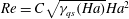 $\mathit{Re}=C\sqrt{{\it\gamma}_{qs}(\mathit{Ha })}\mathit{Ha}^{2}$
and
$\mathit{Re}=C\sqrt{{\it\gamma}_{qs}(\mathit{Ha })}\mathit{Ha}^{2}$
and
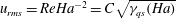 $u_{rms}=\mathit{Re}\mathit{Ha}^{-2}=C\sqrt{{\it\gamma}_{qs}(\mathit{Ha })}$
. We also show in these two figures the results obtained with SFEMaNS with
$u_{rms}=\mathit{Re}\mathit{Ha}^{-2}=C\sqrt{{\it\gamma}_{qs}(\mathit{Ha })}$
. We also show in these two figures the results obtained with SFEMaNS with
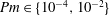 $\mathit{Pm}\in \{10^{-4},10^{-2}\}$
using the formulae
$\mathit{Pm}\in \{10^{-4},10^{-2}\}$
using the formulae
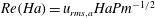 $\mathit{Re}(\mathit{Ha})=u_{rms,a}\mathit{Ha}\mathit{Pm}^{-1/2}$
and
$\mathit{Re}(\mathit{Ha})=u_{rms,a}\mathit{Ha}\mathit{Pm}^{-1/2}$
and
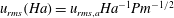 $u_{rms}(\mathit{Ha})=u_{rms,a}\mathit{Ha}^{-1}\mathit{Pm}^{-1/2}$
, where
$u_{rms}(\mathit{Ha})=u_{rms,a}\mathit{Ha}^{-1}\mathit{Pm}^{-1/2}$
, where
 $u_{rms,a}$
is computed with (3.10). There is a reasonable agreement between the theoretical predictions of the weakly nonlinear model and the numerical simulations for
$u_{rms,a}$
is computed with (3.10). There is a reasonable agreement between the theoretical predictions of the weakly nonlinear model and the numerical simulations for
 $C\approx 0.6$
. We have restricted ourselves to
$C\approx 0.6$
. We have restricted ourselves to
 $\mathit{Ha}\leqslant 50$
to be close to the QS limit as specified in table 5.
$\mathit{Ha}\leqslant 50$
to be close to the QS limit as specified in table 5.

Figure 15. Weakly nonlinear saturation of the Tayler instability, theory versus numerics: (a)
 $\mathit{Re}$
versus
$\mathit{Re}$
versus
 $\mathit{Ha}$
, SFEMaNS versus theory; (b)
$\mathit{Ha}$
, SFEMaNS versus theory; (b)
 $u_{rms}$
versus
$u_{rms}$
versus
 $\mathit{Ha}$
, SFEMaNS versus theory; (c)
$\mathit{Ha}$
, SFEMaNS versus theory; (c)
 $\mathit{Re}$
versus
$\mathit{Re}$
versus
 $\mathit{Ha}$
, Weber et al. (Reference Weber, Galindo, Stefani and Weier2014) versus theory; (d)
$\mathit{Ha}$
, Weber et al. (Reference Weber, Galindo, Stefani and Weier2014) versus theory; (d)
 $u_{rms}$
versus
$u_{rms}$
versus
 $\mathit{Ha}$
, Weber et al. (Reference Weber, Galindo, Stefani and Weier2014) versus theory. Theoretical curves for various values of
$\mathit{Ha}$
, Weber et al. (Reference Weber, Galindo, Stefani and Weier2014) versus theory. Theoretical curves for various values of
 $C$
. Numerical results obtained using SFEMaNS (a,b), using the data of Weber et al. (Reference Weber, Galindo, Stefani and Weier2014) (c,d). Note that in (d),
$C$
. Numerical results obtained using SFEMaNS (a,b), using the data of Weber et al. (Reference Weber, Galindo, Stefani and Weier2014) (c,d). Note that in (d),
 $\mathit{Ha}_{c}=19.7$
for the theory and
$\mathit{Ha}_{c}=19.7$
for the theory and
 $\mathit{Ha}_{c}=29$
from Weber et al. (Reference Weber, Galindo, Stefani and Weier2014).
$\mathit{Ha}_{c}=29$
from Weber et al. (Reference Weber, Galindo, Stefani and Weier2014).
In figure 15(c,d), we show the graph of
 $\mathit{Re}=C\sqrt{{\it\gamma}_{qs}(\mathit{Ha })}\mathit{Ha}^{2}$
and
$\mathit{Re}=C\sqrt{{\it\gamma}_{qs}(\mathit{Ha })}\mathit{Ha}^{2}$
and
 $u_{rms}=\mathit{Re}\mathit{Ha}^{-2}=C\sqrt{{\it\gamma}_{qs}(\mathit{Ha })}$
where
$u_{rms}=\mathit{Re}\mathit{Ha}^{-2}=C\sqrt{{\it\gamma}_{qs}(\mathit{Ha })}$
where
 ${\it\gamma}_{qs}(\mathit{Ha})$
is computed using
${\it\gamma}_{qs}(\mathit{Ha})$
is computed using
 $l={\rm\pi}/1.2$
. We also report in this figure results published in Weber et al. (Reference Weber, Galindo, Stefani and Weier2014, figure 6) for a cylinder of aspect ratio
$l={\rm\pi}/1.2$
. We also report in this figure results published in Weber et al. (Reference Weber, Galindo, Stefani and Weier2014, figure 6) for a cylinder of aspect ratio
 $h=2.4$
. The numerical results were obtained using a QS code and with the no-slip boundary condition enforced at the top and bottom lids. These are not exactly the same boundary conditions as those that we have imposed, which explains the slight difference on the value of the threshold. We nonetheless observe that our theoretical predictions work well in this case also for a large range of Hartmann numbers with
$h=2.4$
. The numerical results were obtained using a QS code and with the no-slip boundary condition enforced at the top and bottom lids. These are not exactly the same boundary conditions as those that we have imposed, which explains the slight difference on the value of the threshold. We nonetheless observe that our theoretical predictions work well in this case also for a large range of Hartmann numbers with
 $C\simeq 0.3$
.
$C\simeq 0.3$
.
5. Tayler instability in LMBs
We apply the theories developed above to Mg-based LMBs. After a discussion on material properties, we calculate a critical lateral size of a Mg-based battery and also discuss how large the electrolyte layer should be to avoid a short circuit.
5.1. Physical properties
LMBs are usually composed of three liquid phases with different densities. The top and bottom layers assume the role of the electrodes and the middle layer is the electrolyte. The densities of the liquid metals composing the three layers are chosen so that the assembly is stable under the action of gravity. Three types of assemblies have been considered in the literature for possible industrialization in the near future (Kim et al. Reference Kim, Boysen, Newhouse, Spatocco, Chung, Burke, Bradwell, Jiang, Tomaszowska, Wang, Wei, Ortiz, Barriga, Poizeau and Sadoway2013; Wang et al. Reference Wang, Jiang, Chung, Ouchi, Burke, Boysen, Bradwell, Kim, Muecke and Sadoway2014).
-
(a) Magnesium batteries: Mg (light) for the top electrode,
$\text{MCl}_{2}$
–KCl–NaCl for the electrolyte (intermediate density) and the alloy Sb(Mg) for the bottom (heavy) electrode. -
(b) Sodium batteries: with Na, NaF–NaCl–NaI and Bi(Na) for the top, middle and bottom material, respectively.
-
(c) Lithium batteries: with Li, LiF–LiCl–LiI and a Sb–Pb alloy for the top, middle and bottom material, respectively.

The physical properties of the magnesium LMB at
 $700\,^{\circ }\text{C}$
are listed in table 6 (see also Crawley & Kiff Reference Crawley and Kiff1972 and Sohal et al.
Reference Sohal, Ebner, Sabharwall and Sharpe2013). We also report in this table the corresponding magnetic Prandtl numbers and the relative Hartmann numbers using the Hartmann number of the top layer as a reference,
$700\,^{\circ }\text{C}$
are listed in table 6 (see also Crawley & Kiff Reference Crawley and Kiff1972 and Sohal et al.
Reference Sohal, Ebner, Sabharwall and Sharpe2013). We also report in this table the corresponding magnetic Prandtl numbers and the relative Hartmann numbers using the Hartmann number of the top layer as a reference,
 $\mathit{Ha}_{top}$
. All of the fluids have very low Prandtl numbers and, upon inspection of the relative Hartmann numbers, we conjecture that the Tayler instability is likely to occur first in the top layer, as already suggested in Weber et al. (Reference Weber, Galindo, Stefani, Weier and Wondrak2013).
$\mathit{Ha}_{top}$
. All of the fluids have very low Prandtl numbers and, upon inspection of the relative Hartmann numbers, we conjecture that the Tayler instability is likely to occur first in the top layer, as already suggested in Weber et al. (Reference Weber, Galindo, Stefani, Weier and Wondrak2013).
Table 6. Density
 ${\it\rho}$
, dynamic viscosity
${\it\rho}$
, dynamic viscosity
 ${\it\eta}$
, conductivity
${\it\eta}$
, conductivity
 ${\it\sigma}$
,
${\it\sigma}$
,
 $\mathit{Pm}$
and relative Hartmann number
$\mathit{Pm}$
and relative Hartmann number
 $\mathit{Ha}/\mathit{Ha}_{top}$
of the three fluids composing a magnesium-based LMB.
$\mathit{Ha}/\mathit{Ha}_{top}$
of the three fluids composing a magnesium-based LMB.

Let us now specify some typical dimensions. In the Mg-based LMBs studied in Bradwell et al. (Reference Bradwell, Kim, Sirk and Sadoway2012), the lateral size
 $R$
and height
$R$
and height
 $H$
of the top and bottom electrodes are nearly
$H$
of the top and bottom electrodes are nearly
 $10^{-2}~\text{m}$
. Larger prototypes now reach
$10^{-2}~\text{m}$
. Larger prototypes now reach
 $5\times 10^{-2}~\text{m}\leqslant R\leqslant 15\times 10^{-2}~\text{m}$
for a total height around
$5\times 10^{-2}~\text{m}\leqslant R\leqslant 15\times 10^{-2}~\text{m}$
for a total height around
 $H_{top}+H_{e}+H_{bottom}=5\times 10^{-2}~\text{m}$
. The electrolyte layer is always rather thin,
$H_{top}+H_{e}+H_{bottom}=5\times 10^{-2}~\text{m}$
. The electrolyte layer is always rather thin,
 $H_{e}\leqslant 5\times 10^{-3}~\text{m}$
, since the voltage drop over the resistive electrolyte layer must be smaller than the open circuit voltage of the cell (Weber et al.
Reference Weber, Galindo, Stefani and Weier2014). LMBs are potentially interesting in comparison with other battery technologies if they can be scaled up to larger sizes (possibly reaching
$H_{e}\leqslant 5\times 10^{-3}~\text{m}$
, since the voltage drop over the resistive electrolyte layer must be smaller than the open circuit voltage of the cell (Weber et al.
Reference Weber, Galindo, Stefani and Weier2014). LMBs are potentially interesting in comparison with other battery technologies if they can be scaled up to larger sizes (possibly reaching
 $R>1~\text{m}$
), but the Tayler instability becomes potentially hazardous as the size increases (Stefani et al.
Reference Stefani, Weier, Gundrum and Gerbeth2011).
$R>1~\text{m}$
), but the Tayler instability becomes potentially hazardous as the size increases (Stefani et al.
Reference Stefani, Weier, Gundrum and Gerbeth2011).
An important quantity in LMBs is the typical current density
 $\text{J}_{0}$
. Although it would be desirable to be able to reach high values for
$\text{J}_{0}$
. Although it would be desirable to be able to reach high values for
 $\text{J}_{0}$
, this quantity is limited in practice. For instance, high current densities increase internal resistance losses, which then lower the efficiency of the battery. Also, high
$\text{J}_{0}$
, this quantity is limited in practice. For instance, high current densities increase internal resistance losses, which then lower the efficiency of the battery. Also, high
 $\text{J}_{0}$
require fast ion-exchange rates on the interfaces; this can lead to local depletion/accumulation of the migrating ions (Bradwell et al.
Reference Bradwell, Kim, Sirk and Sadoway2012), which may further reduce the efficiency of the battery. Presently, Mg-based LMB prototypes operate with current densities up to
$\text{J}_{0}$
require fast ion-exchange rates on the interfaces; this can lead to local depletion/accumulation of the migrating ions (Bradwell et al.
Reference Bradwell, Kim, Sirk and Sadoway2012), which may further reduce the efficiency of the battery. Presently, Mg-based LMB prototypes operate with current densities up to
 $\text{J}_{0}=3\times 10^{3}~\text{A}~\text{m}^{-2}$
, see Bradwell et al. (Reference Bradwell, Kim, Sirk and Sadoway2012) and Kelley & Sadoway (Reference Kelley and Sadoway2014). The more recent Li-based LMBs of Wang et al. (Reference Wang, Jiang, Chung, Ouchi, Burke, Boysen, Bradwell, Kim, Muecke and Sadoway2014) have been efficiently cycled with current densities up to
$\text{J}_{0}=3\times 10^{3}~\text{A}~\text{m}^{-2}$
, see Bradwell et al. (Reference Bradwell, Kim, Sirk and Sadoway2012) and Kelley & Sadoway (Reference Kelley and Sadoway2014). The more recent Li-based LMBs of Wang et al. (Reference Wang, Jiang, Chung, Ouchi, Burke, Boysen, Bradwell, Kim, Muecke and Sadoway2014) have been efficiently cycled with current densities up to
 $\text{J}_{0}=10^{4}~\text{A}~\text{m}^{-2}$
. These numbers remain far below the current densities
$\text{J}_{0}=10^{4}~\text{A}~\text{m}^{-2}$
. These numbers remain far below the current densities
 $\text{J}_{0}=10^{5}{-}10^{6}~\text{A}~\text{m}^{-2}$
that are reached in the liquid metal column experiments of Seilmayer et al. (Reference Seilmayer, Stefani, Gundrum, Weier, Gerbeth, Gellert and Rüdiger2012), but it is reasonable to think that larger values of
$\text{J}_{0}=10^{5}{-}10^{6}~\text{A}~\text{m}^{-2}$
that are reached in the liquid metal column experiments of Seilmayer et al. (Reference Seilmayer, Stefani, Gundrum, Weier, Gerbeth, Gellert and Rüdiger2012), but it is reasonable to think that larger values of
 $\text{J}_{0}$
can be reached in the future in the LMB technology. In the rest of the paper we consider the following three scenarios:
$\text{J}_{0}$
can be reached in the future in the LMB technology. In the rest of the paper we consider the following three scenarios:
 $$\begin{eqnarray}(\text{i})\,\,\text{J}_{0}=3\times 10^{3}~\text{A}~\text{m}^{-2},\quad (\text{ii})\,\,\text{J}_{0}=10^{4}~\text{A}~\text{m}^{-2},\quad (\text{iii})\,\,\text{J}_{0}=10^{5}~\text{A}~\text{m}^{-2}\end{eqnarray}$$
to estimate the importance of Tayler’s instability in LMBs.
5.2. Critical size of battery
$R_{c}$
for the Tayler instability

We identify in this section under which conditions the threshold for the Tayler instability can be reached in Mg-based LMBs. As emphasized in Rüdiger et al. (Reference Rüdiger, Gellert, Schultz, Strassmeier, Stefani, Gundrum, Seilmayer and Gerbeth2012), the Hartmann number
 $$\begin{eqnarray}\mathit{Ha}=\frac{{\it\mu}_{0}I_{0}}{2{\rm\pi}}\sqrt{\frac{{\it\sigma}}{{\it\rho}{\it\nu}}},\end{eqnarray}$$
is proportional to the total current
 $I_{0}=\text{J}_{0}{\rm\pi}R^{2}$
passing through the system. Using the physical parameters of the top layer and the minimal critical Hartmann number
$I_{0}=\text{J}_{0}{\rm\pi}R^{2}$
passing through the system. Using the physical parameters of the top layer and the minimal critical Hartmann number
 $\mathit{Ha}_{c,\ast }=19.296$
corresponding to the lowest possible threshold (see (4.26)), we estimate the minimal critical current
$\mathit{Ha}_{c,\ast }=19.296$
corresponding to the lowest possible threshold (see (4.26)), we estimate the minimal critical current
 $$\begin{eqnarray}I_{c}\simeq 1.78~\text{kA}\end{eqnarray}$$
that is necessary to trigger the Tayler instability in the top Mg layer. This order of magnitude matches the experimental value reported in Rüdiger et al. (Reference Rüdiger, Gellert, Schultz, Strassmeier, Stefani, Gundrum, Seilmayer and Gerbeth2012) and Seilmayer et al. (Reference Seilmayer, Stefani, Gundrum, Weier, Gerbeth, Gellert and Rüdiger2012) for a column of liquid Galinstan. Given
 $I_{c}$
and the three scenarios for
$I_{c}$
and the three scenarios for
 $\text{J}_{0}$
defined above, we can estimate the order of magnitude for critical lateral battery sizes
$\text{J}_{0}$
defined above, we can estimate the order of magnitude for critical lateral battery sizes
 $$\begin{eqnarray}(\text{i})~R_{c}\simeq 0.436~\text{m},\quad (\text{ii})~R_{c}\simeq 0.239~\text{m},\quad (\text{iii})~R_{c}\simeq 0.075~\text{m}.\end{eqnarray}$$
The Tayler instability is not to be expected to occur in LMBs with lateral dimension
 $R<R_{c}$
. For instance, the prototype Mg-based batteries currently available on the market fall into the category (i). Since for these batteries
$R<R_{c}$
. For instance, the prototype Mg-based batteries currently available on the market fall into the category (i). Since for these batteries
 $R\lesssim 0.15~\text{m}$
, so far, it is safe to say that the Tayler instability cannot occur in these cells. However, if LMB technology should reach higher standards on
$R\lesssim 0.15~\text{m}$
, so far, it is safe to say that the Tayler instability cannot occur in these cells. However, if LMB technology should reach higher standards on
 $\text{J}_{0}$
like in case (iii), the Tayler instability might occur in cells as small as the present prototypes.
$\text{J}_{0}$
like in case (iii), the Tayler instability might occur in cells as small as the present prototypes.
As observed by Weber et al. (Reference Weber, Galindo, Stefani, Weier and Wondrak2013, Reference Weber, Galindo, Stefani and Weier2014), the critical Hartmann number increases sharply in cells with small aspect ratios; hence, one needs to take into account the influence of the aspect ratio
 $h$
of the cells to make better estimates. Using the data of figure 11 and the wavenumber–aspect ratio relation
$h$
of the cells to make better estimates. Using the data of figure 11 and the wavenumber–aspect ratio relation
 $l=n{\rm\pi}/h$
, we can calculate the critical current
$l=n{\rm\pi}/h$
, we can calculate the critical current
 $I_{c}(h)$
as a function of the aspect ratio
$I_{c}(h)$
as a function of the aspect ratio
 $h$
of the top electrode and for different numbers of rolls in the vertical direction, say
$h$
of the top electrode and for different numbers of rolls in the vertical direction, say
 $n=1,2,3$
. Given
$n=1,2,3$
. Given
 $\text{J}_{0}$
, we then calculate the critical lateral size
$\text{J}_{0}$
, we then calculate the critical lateral size
 $R_{c}(h)$
as a function of the aspect ratio
$R_{c}(h)$
as a function of the aspect ratio
 $h$
of the electrode. We show in figure 16 the marginal stability curves thus obtained (we take the lowest
$h$
of the electrode. We show in figure 16 the marginal stability curves thus obtained (we take the lowest
 $R_{c}(h)$
number for
$R_{c}(h)$
number for
 $n\in \{1,2,3\}$
). Flat cells have to be very large to become Tayler unstable, but as the aspect ratio reaches 1, all of the curves level off to the optimal values given in (5.4). These curves give an idea on the possibilities of the occurrence of the Tayler instability in LMBs using present day and future technology. All of the prototype cells (represented by rectangles in figure 16) are well beneath the marginal stability curve corresponding to case (i), i.e.
$n\in \{1,2,3\}$
). Flat cells have to be very large to become Tayler unstable, but as the aspect ratio reaches 1, all of the curves level off to the optimal values given in (5.4). These curves give an idea on the possibilities of the occurrence of the Tayler instability in LMBs using present day and future technology. All of the prototype cells (represented by rectangles in figure 16) are well beneath the marginal stability curve corresponding to case (i), i.e.
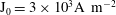 $\text{J}_{0}=3\times 10^{3}\text{A}~\text{m}^{-2}$
. The Tayler instability is not an issue for these batteries.
$\text{J}_{0}=3\times 10^{3}\text{A}~\text{m}^{-2}$
. The Tayler instability is not an issue for these batteries.

Figure 16. Estimated phase diagram for the occurrence of the Tayler instability in Mg-based LMBs in terms of physical dimensions and for the three
 $\text{J}_{0}$
-scenarios: (i)
$\text{J}_{0}$
-scenarios: (i)
 $\text{J}_{0}=3\times 10^{3}~\text{A}~\text{m}^{-2}$
; (ii)
$\text{J}_{0}=3\times 10^{3}~\text{A}~\text{m}^{-2}$
; (ii)
 $\text{J}_{0}=10^{4}~\text{A}~\text{m}^{-2}$
; (iii)
$\text{J}_{0}=10^{4}~\text{A}~\text{m}^{-2}$
; (iii)
 $\text{J}_{0}=10^{5}~\text{A}~\text{m}^{-2}$
. There is a risk of Tayler instabilities only in batteries of horizontal size
$\text{J}_{0}=10^{5}~\text{A}~\text{m}^{-2}$
. There is a risk of Tayler instabilities only in batteries of horizontal size
 $r>R_{c}$
. Various flows with different numbers of cells
$r>R_{c}$
. Various flows with different numbers of cells
 $n=1,2,3$
in the vertical direction can occur at the onset of instability. Rectangles indicate estimated dimensions of LMB prototypes.
$n=1,2,3$
in the vertical direction can occur at the onset of instability. Rectangles indicate estimated dimensions of LMB prototypes.
5.3. Critical electrolyte thickness
$H_{e,c}$
for short circuit

It is essential in LMBs to avoid short circuits between the top and bottom layers (Stefani et al.
Reference Stefani, Weier, Gundrum and Gerbeth2011; Weber et al.
Reference Weber, Galindo, Stefani and Weier2014). Short circuits are possible when the fluids move sufficiently fast so that the thickness of the electrolyte layer becomes negligible at some point, thereby allowing the fluid from the top electrode to get in contact with the fluid from the bottom electrode. Using a simple energy argument, we now estimate the critical thickness of the electrolyte layer,
 $H_{e,c}$
, above which short circuits caused by the Tayler instability should not happen.
$H_{e,c}$
, above which short circuits caused by the Tayler instability should not happen.
Considering the nonlinear scaling (4.38), compatible with the results of Weber et al. (Reference Weber, Galindo, Stefani and Weier2014), we estimate the kinetic energy density of the flow:
 $$\begin{eqnarray}e_{kin}=\frac{{\it\rho}U_{T}^{2}}{2}=\frac{C^{2}{\it\gamma}_{qs}}{2}\frac{{\it\sigma}^{2}B_{0}^{4}R^{2}}{{\it\rho}}=\frac{C^{2}{\it\gamma}_{qs}}{32}\frac{{\it\sigma}^{2}{\it\mu}_{0}^{4}\text{J}_{0}^{4}R^{6}}{{\it\rho}},\end{eqnarray}$$
where
 ${\it\gamma}_{qs}(\mathit{Ha})$
is the non-dimensional QS growth rate calculated using the linear stability analysis. Parts of this kinetic energy will be transformed into gravitational potential energy as the fluid interfaces start moving. Since the fluid composing the bottom layer is significantly heavier than both that of the electrolyte and the top layer, wavy motions of the interfaces are more likely to occur at the upper electrode–electrolyte interface. We therefore consider a simplified short-circuit model in which a parcel of fluid from the top electrode moves across the electrolyte layer towards the lower electrode. This event increases the density of gravitational potential energy of the amount
${\it\gamma}_{qs}(\mathit{Ha})$
is the non-dimensional QS growth rate calculated using the linear stability analysis. Parts of this kinetic energy will be transformed into gravitational potential energy as the fluid interfaces start moving. Since the fluid composing the bottom layer is significantly heavier than both that of the electrolyte and the top layer, wavy motions of the interfaces are more likely to occur at the upper electrode–electrolyte interface. We therefore consider a simplified short-circuit model in which a parcel of fluid from the top electrode moves across the electrolyte layer towards the lower electrode. This event increases the density of gravitational potential energy of the amount
 $$\begin{eqnarray}e_{pot}=({\it\rho}_{e}-{\it\rho}_{top})gH_{e}.\end{eqnarray}$$
It seems reasonable then to assume that a short-circuit happens when all the available kinetic energy is transformed into potential energy. The statement
 $e_{kin}=e_{pot}$
yields a critical thickness of the electrolyte layer:
$e_{kin}=e_{pot}$
yields a critical thickness of the electrolyte layer:
 $$\begin{eqnarray}H_{e,c}=\frac{C^{2}{\it\gamma}_{qs}(\mathit{Ha})}{32}\frac{{\it\sigma}_{top}^{2}{\it\mu}_{0}^{4}\text{J}_{0}^{4}R^{6}}{{\it\rho}_{top}({\it\rho}_{e}-{\it\rho}_{top})g}.\end{eqnarray}$$
A configuration where
 $H_{e}>H_{e,c}$
has not enough kinetic energy available to allow for a short circuit and may thus be considered safe. Conversely, it is unlikely that
$H_{e}>H_{e,c}$
has not enough kinetic energy available to allow for a short circuit and may thus be considered safe. Conversely, it is unlikely that
 $H_{e}<H_{e,c}$
immediately implies that short circuits will happen, but the configuration starts to be unsafe. Note finally that the above argument is essentially the same as applying Bernoulli’s conservation law to the three-layer fluid system.
$H_{e}<H_{e,c}$
immediately implies that short circuits will happen, but the configuration starts to be unsafe. Note finally that the above argument is essentially the same as applying Bernoulli’s conservation law to the three-layer fluid system.
Since the above formula suggests a very fast increase of
 $H_{e,c}\sim R^{6}$
with respect to the horizontal size of the battery, one may be led to think that
$H_{e,c}\sim R^{6}$
with respect to the horizontal size of the battery, one may be led to think that
 $H_{e,c}$
quickly becomes very large, thereby excluding the possibility of building very large LMBs. To evaluate this idea quantitatively, let us apply the estimate (5.7) to Mg-based LMBs using the three scenarios stated in (5.1) for
$H_{e,c}$
quickly becomes very large, thereby excluding the possibility of building very large LMBs. To evaluate this idea quantitatively, let us apply the estimate (5.7) to Mg-based LMBs using the three scenarios stated in (5.1) for
 $\text{J}_{0}$
.
$\text{J}_{0}$
.
We calculate
 ${\it\gamma}_{qs}(\mathit{Ha})$
for a large range of Hartmann numbers using the linear theory for the optimal cylinder height
${\it\gamma}_{qs}(\mathit{Ha})$
for a large range of Hartmann numbers using the linear theory for the optimal cylinder height
 $h_{top}=2.77$
, with wavenumber
$h_{top}=2.77$
, with wavenumber
 $l=2{\rm\pi}/2.77$
. This is the worst-case scenario since it gives the smallest threshold for the configuration that fits two counter-rotating vortices in the box. For very large
$l=2{\rm\pi}/2.77$
. This is the worst-case scenario since it gives the smallest threshold for the configuration that fits two counter-rotating vortices in the box. For very large
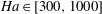 $\mathit{Ha}\in [300,1000]$
we use the asymptotical value
$\mathit{Ha}\in [300,1000]$
we use the asymptotical value
 ${\it\gamma}_{nvqs}=0.0512$
. Then we compute
${\it\gamma}_{nvqs}=0.0512$
. Then we compute
 $H_{e,c}$
as a function of the horizontal size
$H_{e,c}$
as a function of the horizontal size
 $R$
by using the different material properties, the relation
$R$
by using the different material properties, the relation
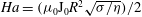 $\mathit{Ha}=({\it\mu}_{0}\text{J}_{0}R^{2}\sqrt{{\it\sigma}/{\it\eta}})/2$
,
$\mathit{Ha}=({\it\mu}_{0}\text{J}_{0}R^{2}\sqrt{{\it\sigma}/{\it\eta}})/2$
,
 $C=0.6$
,
$C=0.6$
,
 $g=9.81~\text{m}~\text{s}^{-2}$
and the three values of
$g=9.81~\text{m}~\text{s}^{-2}$
and the three values of
 $\text{J}_{0}$
defined in (5.1). The results are shown in figure 17; the highlighted band shows the typical range of the thickness of the electrolyte,
$\text{J}_{0}$
defined in (5.1). The results are shown in figure 17; the highlighted band shows the typical range of the thickness of the electrolyte,
 $H_{e,c}\in [1,5]\times 10^{-3}~\text{m}$
. This figure clearly shows the steep increase
$H_{e,c}\in [1,5]\times 10^{-3}~\text{m}$
. This figure clearly shows the steep increase
 ${\sim}R^{6}$
and the dependence on
${\sim}R^{6}$
and the dependence on
 $\text{J}_{0}$
; it also shows that LMBs with radius such that
$\text{J}_{0}$
; it also shows that LMBs with radius such that
 $$\begin{eqnarray}(\text{i})~R\leqslant 3.14~\text{m},\quad (\text{ii})~R\leqslant 1.40~\text{m},\quad (\text{iii})~R\leqslant 0.30~\text{m}\end{eqnarray}$$
should not suffer from short circuits induced by the Tayler instability with an electrolyte layer only 1 mm thick,
 $H_{e,c}=10^{-3}~\text{m}$
. Short circuits can be expected only in very large batteries,
$H_{e,c}=10^{-3}~\text{m}$
. Short circuits can be expected only in very large batteries,
 $R>3~\text{m}$
, with the present-day technology of Mg-based LMBs (case (i)). But if the standards evolve so much that
$R>3~\text{m}$
, with the present-day technology of Mg-based LMBs (case (i)). But if the standards evolve so much that
 $\text{J}_{0}$
can be as high as in case (iii), cells of radius exceeding 0.30 m may become unsafe.
$\text{J}_{0}$
can be as high as in case (iii), cells of radius exceeding 0.30 m may become unsafe.

Figure 17. Critical height of the electrolyte layer
 $H_{e,c}$
versus
$H_{e,c}$
versus
 $R$
for three current density
$R$
for three current density
 $\text{J}_{0}$
-scenarios: (i)
$\text{J}_{0}$
-scenarios: (i)
 $\text{J}_{0}=3\times 10^{3}~\text{A}~\text{m}^{-2}$
; (ii)
$\text{J}_{0}=3\times 10^{3}~\text{A}~\text{m}^{-2}$
; (ii)
 $\text{J}_{0}=10^{4}~\text{A}~\text{m}^{-2}$
; (iii)
$\text{J}_{0}=10^{4}~\text{A}~\text{m}^{-2}$
; (iii)
 $\text{J}_{0}=10^{5}~\text{A}~\text{m}^{-2}$
. Dimensions are in metres. Dashed lines correspond to the high Hartmann number range:
$\text{J}_{0}=10^{5}~\text{A}~\text{m}^{-2}$
. Dimensions are in metres. Dashed lines correspond to the high Hartmann number range:
 $\mathit{Ha}\in [300,1000]$
(calculated using the asymptotical value of
$\mathit{Ha}\in [300,1000]$
(calculated using the asymptotical value of
 ${\it\gamma}_{nvqs}$
). Arrows indicate critical battery sizes
${\it\gamma}_{nvqs}$
). Arrows indicate critical battery sizes
 $R_{c}$
.
$R_{c}$
.
5.4. Simulation of the Tayler instability in a model LMB under low gravity
We now want to simulate a multiphase configuration resembling a LMB in order to test the reliability of the critical electrolyte thickness criterion (5.7). For this purpose, we rewrite (3.3) to account for the action of gravity and the fact that the density, the dynamic viscosity and the electrical conductivity are no longer constant. The new non-dimensional system (3.3) takes the following form:
 $$\begin{eqnarray}\left.\begin{array}{@{}c@{}}\displaystyle {\it\rho}(\partial _{t}\boldsymbol{U}+\boldsymbol{U}\boldsymbol{\cdot }\boldsymbol{{\rm\nabla}}\boldsymbol{U})=-\boldsymbol{{\rm\nabla}}P+(\boldsymbol{{\rm\nabla}}\times \boldsymbol{B})\times \boldsymbol{B}+2\frac{\sqrt{\mathit{Pm }_{top}}}{\mathit{Ha}_{top}}\boldsymbol{{\rm\nabla}}\boldsymbol{\cdot }\left({\it\eta}\boldsymbol{{\rm\nabla}}^{s}\boldsymbol{U}\right)-\frac{1}{\mathit{Fr}_{top}}{\it\rho}\boldsymbol{e}_{z},\\ \displaystyle \partial _{t}\boldsymbol{B}=\boldsymbol{{\rm\nabla}}\times (\boldsymbol{U}\times \boldsymbol{B})-\frac{1}{\mathit{Ha}_{top}\sqrt{\mathit{Pm }_{top}}}\boldsymbol{{\rm\nabla}}\times \left(\frac{1}{{\it\sigma}}\boldsymbol{{\rm\nabla}}\times \boldsymbol{B}\right),\\ \boldsymbol{{\rm\nabla}}\boldsymbol{\cdot }\boldsymbol{U}=0,\end{array}\right\}\end{eqnarray}$$
where
 $\boldsymbol{{\rm\nabla}}^{s}\boldsymbol{U}=(\boldsymbol{{\rm\nabla}}\boldsymbol{U}+\boldsymbol{{\rm\nabla}}\boldsymbol{U}^{\text{T}})/2$
is the strain rate tensor, and the Hartmann and Prandtl numbers are computed using the conductivity and dynamic viscosity of the top layer. The Froude number is here defined by
$\boldsymbol{{\rm\nabla}}^{s}\boldsymbol{U}=(\boldsymbol{{\rm\nabla}}\boldsymbol{U}+\boldsymbol{{\rm\nabla}}\boldsymbol{U}^{\text{T}})/2$
is the strain rate tensor, and the Hartmann and Prandtl numbers are computed using the conductivity and dynamic viscosity of the top layer. The Froude number is here defined by
 $$\begin{eqnarray}\mathit{Fr}_{top}=\frac{{\it\mu}_{0}\text{J}_{0}^{2}R}{4{\it\rho}_{top}g}.\end{eqnarray}$$
The fields
 ${\it\rho}$
,
${\it\rho}$
,
 ${\it\sigma}$
,
${\it\sigma}$
,
 ${\it\eta}$
are non-dimensionalized by using the values of the top liquid layer and are reconstructed in SFEMaNS by using two level set functions
${\it\eta}$
are non-dimensionalized by using the values of the top liquid layer and are reconstructed in SFEMaNS by using two level set functions
 ${\it\Phi}_{i}$
, one for the bottom interface,
${\it\Phi}_{i}$
, one for the bottom interface,
 $i=1$
, and one for the top interface,
$i=1$
, and one for the top interface,
 $i=2$
with
$i=2$
with
 $0\leqslant {\it\Phi}_{i}\leqslant 1$
. For instance, the density is reconstructed as follows:
$0\leqslant {\it\Phi}_{i}\leqslant 1$
. For instance, the density is reconstructed as follows:
 $$\begin{eqnarray}{\it\rho}=\left((1-{\it\Phi}_{1})\frac{{\it\rho}_{bot}}{{\it\rho}_{top}}+{\it\Phi}_{1}\frac{{\it\rho}_{e}}{{\it\rho}_{top}}\right)(1-{\it\Phi}_{2})+{\it\Phi}_{2},\end{eqnarray}$$
and
 ${\it\eta}$
and
${\it\eta}$
and
 ${\it\sigma}$
are reconstructed similarly. Both level set functions are advected by the flow and are thus computed by solving the transport equations
${\it\sigma}$
are reconstructed similarly. Both level set functions are advected by the flow and are thus computed by solving the transport equations
 $$\begin{eqnarray}\partial _{t}{\it\Phi}_{i}+\boldsymbol{U}\boldsymbol{\cdot }\boldsymbol{{\rm\nabla}}{\it\Phi}_{i}=0,\quad i=1,2.\end{eqnarray}$$
The computation is done in SFEMaNS by augmenting (5.12) with an artificial diffusion based on entropy residuals; we refer to Guermond, Pasquetti & Popov (Reference Guermond, Pasquetti and Popov2011b
) for more details. The profiles of the interfaces are kept sharp (but smooth) by using a compression technique. Typical profiles at rest of
 ${\it\Phi}_{1}$
and
${\it\Phi}_{1}$
and
 ${\it\Phi}_{2}$
along the vertical direction are shown in figure 18; the thickness of the electrolyte layer is
${\it\Phi}_{2}$
along the vertical direction are shown in figure 18; the thickness of the electrolyte layer is
 $h_{e}=0.1$
. The boundary conditions at
$h_{e}=0.1$
. The boundary conditions at
 $r=1^{-}$
are the same as in (3.5) and the TB-BC are chosen to be stress-free in the simulations reported below. No boundary condition is needed for
$r=1^{-}$
are the same as in (3.5) and the TB-BC are chosen to be stress-free in the simulations reported below. No boundary condition is needed for
 ${\it\Phi}_{i}$
, since we enforce
${\it\Phi}_{i}$
, since we enforce
 $\boldsymbol{U}\boldsymbol{\cdot }\boldsymbol{n}=0$
over the entire boundary of the container.
$\boldsymbol{U}\boldsymbol{\cdot }\boldsymbol{n}=0$
over the entire boundary of the container.

Figure 18. Profiles of the level set functions
 ${\it\Phi}_{1}$
and
${\it\Phi}_{1}$
and
 ${\it\Phi}_{2}$
in a vertical cut of the cylinder at rest for
${\it\Phi}_{2}$
in a vertical cut of the cylinder at rest for
 $\mathit{Ha}_{top}=15.8$
. The level set functions jump sharply from 0 to 1.
$\mathit{Ha}_{top}=15.8$
. The level set functions jump sharply from 0 to 1.
Let us now test the critical electrolyte thickness criterion (5.7) in a Mg-based LMB with
 $\text{J}_{0}=3\times 10^{3}~\text{A}~\text{m}^{-2}$
. We use the parameters listed in table 7, which correspond to realistic Mg batteries except for
$\text{J}_{0}=3\times 10^{3}~\text{A}~\text{m}^{-2}$
. We use the parameters listed in table 7, which correspond to realistic Mg batteries except for
 $\mathit{Pm}$
,
$\mathit{Pm}$
,
 ${\it\sigma}_{e}/{\it\sigma}_{top}$
and
${\it\sigma}_{e}/{\it\sigma}_{top}$
and
 $\mathit{Fr}$
. In its current form the time-stepping code cannot handle Prandtl numbers as low as
$\mathit{Fr}$
. In its current form the time-stepping code cannot handle Prandtl numbers as low as
 $2.24\times 10^{-9}\leqslant \mathit{Pm}\leqslant 3.49\times 10^{-6}$
, but the analysis of the Tayler instability suggests that we should obtain the same dynamics by using
$2.24\times 10^{-9}\leqslant \mathit{Pm}\leqslant 3.49\times 10^{-6}$
, but the analysis of the Tayler instability suggests that we should obtain the same dynamics by using
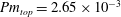 $\mathit{Pm}_{top}=2.65\times 10^{-3}$
when
$\mathit{Pm}_{top}=2.65\times 10^{-3}$
when
 $\mathit{Ha}$
is not too large (see table 5). We also reduced the conductivity ratio between the top electrode and the electrolyte for numerical stability reasons, but we expect this modification to have little impact since the electrolyte layer is thin.
$\mathit{Ha}$
is not too large (see table 5). We also reduced the conductivity ratio between the top electrode and the electrolyte for numerical stability reasons, but we expect this modification to have little impact since the electrolyte layer is thin.
Table 7. Non-dimensional parameters for the Mg-based LMB and the numerical model.

We focus on three cases:
 $\mathit{Ha}_{top}=15.8,23.7,47.3$
corresponding to batteries with radii
$\mathit{Ha}_{top}=15.8,23.7,47.3$
corresponding to batteries with radii
 $R=0.394,0.483,0.682~\text{m}$
, respectively. The aspect ratios of the electrodes at rest are
$R=0.394,0.483,0.682~\text{m}$
, respectively. The aspect ratios of the electrodes at rest are
 $h_{top}=h_{bot}=2.77$
. We rewrite the pinch criterion (5.7) in non-dimensional form as follows:
$h_{top}=h_{bot}=2.77$
. We rewrite the pinch criterion (5.7) in non-dimensional form as follows:
 $$\begin{eqnarray}h_{e,c}=\frac{C^{2}{\it\gamma}_{qs}(\mathit{Ha}_{top})}{2}\frac{\mathit{Fr}_{top}\mathit{Ha}_{top}^{2}\mathit{Pm}_{top}}{{\it\rho}_{e}/{\it\rho}_{top}-1}.\end{eqnarray}$$
As discussed previously, a short-circuit event in a Mg-based LMB at low
 $\mathit{Ha}$
number would require tiny electrolyte layers of aspect ratios
$\mathit{Ha}$
number would require tiny electrolyte layers of aspect ratios
 $h<h_{e,c}\simeq 10^{-8}{-}10^{-7}$
(see table 7). Since these values are numerically unfeasible, we are going to work with a larger value of
$h<h_{e,c}\simeq 10^{-8}{-}10^{-7}$
(see table 7). Since these values are numerically unfeasible, we are going to work with a larger value of
 $\mathit{Fr}_{top}$
in the numerical model, i.e. we choose
$\mathit{Fr}_{top}$
in the numerical model, i.e. we choose
 $\mathit{Fr}_{top}=0.633$
. This is equivalent to underestimating
$\mathit{Fr}_{top}=0.633$
. This is equivalent to underestimating
 $g$
by many orders of magnitude, thereby making it easier for the interfaces to undergo large deformations. By letting the thickness electrolyte to be
$g$
by many orders of magnitude, thereby making it easier for the interfaces to undergo large deformations. By letting the thickness electrolyte to be
 $h_{e}=0.1$
, we expect no breaking of the electrolyte layer for
$h_{e}=0.1$
, we expect no breaking of the electrolyte layer for
 $\mathit{Ha}_{top}=23.7$
, since (5.13) gives
$\mathit{Ha}_{top}=23.7$
, since (5.13) gives
 $h_{e,c}=0.044<h_{e}$
; however, we should come close to short circuit for
$h_{e,c}=0.044<h_{e}$
; however, we should come close to short circuit for
 $\mathit{Ha}_{top}=47.3$
since (5.13) gives
$\mathit{Ha}_{top}=47.3$
since (5.13) gives
 $h_{e,c}=0.45>h_{e}$
.
$h_{e,c}=0.45>h_{e}$
.
Figure 19(a) shows the time evolution of
 $u_{rms,a}$
for the three cases considered,
$u_{rms,a}$
for the three cases considered,
 $\mathit{Ha}_{top}=15.8,23.7,47.3$
. The kinetic energy remains at a very low level and the system essentially stays at rest for
$\mathit{Ha}_{top}=15.8,23.7,47.3$
. The kinetic energy remains at a very low level and the system essentially stays at rest for
 $\mathit{Ha}_{top}=15.8$
. Above the Tayler instability threshold, the energy increases exponentially and saturates for
$\mathit{Ha}_{top}=15.8$
. Above the Tayler instability threshold, the energy increases exponentially and saturates for
 $\mathit{Ha}_{top}=23.7$
. The third curve in figure 19(a) shows the time evolution of
$\mathit{Ha}_{top}=23.7$
. The third curve in figure 19(a) shows the time evolution of
 $u_{rms,a}$
for the solution corresponding to
$u_{rms,a}$
for the solution corresponding to
 $\mathit{Ha}_{top}=47.3$
using as initial data the asymptotic state for
$\mathit{Ha}_{top}=47.3$
using as initial data the asymptotic state for
 $\mathit{Ha}_{top}=23.7$
at time
$\mathit{Ha}_{top}=23.7$
at time
 $t=4000$
; we observe a sharp increase of the energy until the electrolyte layer pinches at time
$t=4000$
; we observe a sharp increase of the energy until the electrolyte layer pinches at time
 $t=4050$
.
$t=4050$
.

Figure 19. Tayler instability in a LMB: (a) time evolution of the r.m.s. velocity for
 $\mathit{Ha}_{top}=15.8,23.7$
and 47.3; (b) final time interface deformation for
$\mathit{Ha}_{top}=15.8,23.7$
and 47.3; (b) final time interface deformation for
 $\mathit{Ha}_{top}=15.8$
at time
$\mathit{Ha}_{top}=15.8$
at time
 $t=2000$
, for
$t=2000$
, for
 $\mathit{Ha}_{top}=23.7$
at time
$\mathit{Ha}_{top}=23.7$
at time
 $t=4000$
and for
$t=4000$
and for
 $\mathit{Ha}_{top}=47.3$
at time
$\mathit{Ha}_{top}=47.3$
at time
 $t=4050$
(after restarting). The top interface is deformed by the flow in the top layer for
$t=4050$
(after restarting). The top interface is deformed by the flow in the top layer for
 $\mathit{Ha}_{top}=23.7$
while the two interfaces osculate for
$\mathit{Ha}_{top}=23.7$
while the two interfaces osculate for
 $\mathit{Ha}_{top}=47.3$
.
$\mathit{Ha}_{top}=47.3$
.

Figure 20. Tayler instability in a LMB: (a) initial condition,
 $\mathit{Ha}=15.8$
; (b)
$\mathit{Ha}=15.8$
; (b)
 $t=4000$
,
$t=4000$
,
 $\mathit{Ha}=23.7$
,
$\mathit{Ha}=23.7$
,
 $B_{z}$
blobs; (c)
$B_{z}$
blobs; (c)
 $t=4000$
,
$t=4000$
,
 $\mathit{Ha}=23.7$
, velocity field; (d)
$\mathit{Ha}=23.7$
, velocity field; (d)
 $t=4050$
,
$t=4050$
,
 $\mathit{Ha}=47.3$
,
$\mathit{Ha}=47.3$
,
 $B_{z}$
blobs; (e)
$B_{z}$
blobs; (e)
 $t=4050$
,
$t=4050$
,
 $\mathit{Ha}=47.3$
, velocity field. Here
$\mathit{Ha}=47.3$
, velocity field. Here
 $B_{z}$
contours visualize
$B_{z}$
contours visualize
 $\pm 10\,\%$
of the maximum and minimum value, velocity field plots are coloured by
$\pm 10\,\%$
of the maximum and minimum value, velocity field plots are coloured by
 $U_{z}$
. The top and bottom interfaces are visualized by isosurfaces
$U_{z}$
. The top and bottom interfaces are visualized by isosurfaces
 ${\it\Phi}_{1}=0.5$
(yellow online or light gray) and
${\it\Phi}_{1}=0.5$
(yellow online or light gray) and
 ${\it\Phi}_{2}=0.5$
(green online or black).
${\it\Phi}_{2}=0.5$
(green online or black).
The three insets in figure 19(b) show the two iso-interfaces
 ${\it\Phi}_{1}={\it\Phi}_{2}=0.5$
in a meridian section; there is one inset for each value of
${\it\Phi}_{1}={\it\Phi}_{2}=0.5$
in a meridian section; there is one inset for each value of
 $\mathit{Ha}_{top}$
. No deformation is noticeable on both interfaces for
$\mathit{Ha}_{top}$
. No deformation is noticeable on both interfaces for
 $\mathit{Ha}_{top}=15.8$
. For
$\mathit{Ha}_{top}=15.8$
. For
 $\mathit{Ha}_{top}=23.7$
, the interface between the top layer and the electrolyte is deformed, whereas the interface between the bottom layer and the electrolyte remains almost flat. In agreement with our critical electrolyte height criterion, the deformation is not large enough to pinch the electrolyte layer. Doubling the Hartmann number to
$\mathit{Ha}_{top}=23.7$
, the interface between the top layer and the electrolyte is deformed, whereas the interface between the bottom layer and the electrolyte remains almost flat. In agreement with our critical electrolyte height criterion, the deformation is not large enough to pinch the electrolyte layer. Doubling the Hartmann number to
 $\mathit{Ha}_{top}=47.3$
, creates a more vigorous flow in the top layer which succeeds in washing away parts of the electrolyte to a point where the two interfaces nearly osculate. The occurrence of a pinch for this set of parameters is compatible with our estimate (5.13), since
$\mathit{Ha}_{top}=47.3$
, creates a more vigorous flow in the top layer which succeeds in washing away parts of the electrolyte to a point where the two interfaces nearly osculate. The occurrence of a pinch for this set of parameters is compatible with our estimate (5.13), since
 $h_{e}=0.1<h_{e,c}$
.
$h_{e}=0.1<h_{e,c}$
.
Figure 20 finally shows some 3D snapshots of the system. In 20(a), we see the two interfaces separating the three fluids at the beginning of the computation for
 $\mathit{Ha}=15.8$
and 23.7. For
$\mathit{Ha}=15.8$
and 23.7. For
 $\mathit{Ha}_{top}=15.8$
there is no Tayler instability and the interfaces remain flat at all times. In contrast, for
$\mathit{Ha}_{top}=15.8$
there is no Tayler instability and the interfaces remain flat at all times. In contrast, for
 $\mathit{Ha}_{top}=23.7$
, the Tayler mechanism destabilizes the top layer, see figure 20(b,c). There are two counter-rotating vortices and a pair of magnetic field perturbations in quadrature in the top layer. Only small motions occur in the bottom layer. For
$\mathit{Ha}_{top}=23.7$
, the Tayler mechanism destabilizes the top layer, see figure 20(b,c). There are two counter-rotating vortices and a pair of magnetic field perturbations in quadrature in the top layer. Only small motions occur in the bottom layer. For
 $\mathit{Ha}_{top}=47.3$
, the Tayler counter-rotating vortices in the top layer are so strong that a contact is established between the two interfaces and a short circuit occurs.
$\mathit{Ha}_{top}=47.3$
, the Tayler counter-rotating vortices in the top layer are so strong that a contact is established between the two interfaces and a short circuit occurs.
6. Conclusion
We have studied the Tayler instability in liquid metal columns and in LMBs using numerical and theoretical approaches.
The main conclusions from the numerical investigations on single-phase simulations are the following. In agreement with previous results (Rüdiger et al.
Reference Rüdiger, Schultz and Gellert2011, Reference Rüdiger, Gellert, Schultz, Strassmeier, Stefani, Gundrum, Seilmayer and Gerbeth2012; Weber et al.
Reference Weber, Galindo, Stefani, Weier and Wondrak2013, Reference Weber, Galindo, Stefani and Weier2014), we find only
 $m=1$
unstable modes, which can be helical or phase fixed depending on the initial conditions and the boundary conditions at the top and bottom lids. The use of simplified boundary conditions at the cylindrical boundary
$m=1$
unstable modes, which can be helical or phase fixed depending on the initial conditions and the boundary conditions at the top and bottom lids. The use of simplified boundary conditions at the cylindrical boundary
 $r=1^{-}$
seems to have a small impact on Tayler’s instability. We have observed saturated states and seen how different unstable modes compete in the nonlinear regime. Secondary instabilities have also been observed and can be induced by the use of periodic boundary conditions. Finally we have produced quantitative data to allow careful comparisons with theoretical models.
$r=1^{-}$
seems to have a small impact on Tayler’s instability. We have observed saturated states and seen how different unstable modes compete in the nonlinear regime. Secondary instabilities have also been observed and can be induced by the use of periodic boundary conditions. Finally we have produced quantitative data to allow careful comparisons with theoretical models.
In the theoretical section devoted to the liquid metal column, we have performed a linear stability analysis using the method of Tayler (Reference Tayler1957, Reference Tayler1960). We observe excellent agreements with the numerical simulations. We also explain why helical modes do not spontaneously emerge in finite cylinders with impermeable walls. Near threshold, the Tayler instability always appears in QS form, and
 $m=1$
modes grow on the time-scale
$m=1$
modes grow on the time-scale
 ${\it\rho}/{\it\sigma}B_{0}^{2}$
in agreement with previous work (see Rüdiger et al.
Reference Rüdiger, Schultz and Gellert2011, Reference Rüdiger, Gellert, Schultz, Strassmeier, Stefani, Gundrum, Seilmayer and Gerbeth2012). We observe that there exists a transitional Hartmann number
${\it\rho}/{\it\sigma}B_{0}^{2}$
in agreement with previous work (see Rüdiger et al.
Reference Rüdiger, Schultz and Gellert2011, Reference Rüdiger, Gellert, Schultz, Strassmeier, Stefani, Gundrum, Seilmayer and Gerbeth2012). We observe that there exists a transitional Hartmann number
 $\mathit{Ha}_{tr}(\mathit{Pm})$
such that the quasistatic approximation applies when
$\mathit{Ha}_{tr}(\mathit{Pm})$
such that the quasistatic approximation applies when
 $\mathit{Ha}\in [\mathit{Ha}_{c},\mathit{Ha}_{tr}(\mathit{Pm})]$
. This information allows us to perform numerical simulations with larger
$\mathit{Ha}\in [\mathit{Ha}_{c},\mathit{Ha}_{tr}(\mathit{Pm})]$
. This information allows us to perform numerical simulations with larger
 $\mathit{Pm}$
than in reality without compromising the physics. In a short discussion on the nonlinear regime, we show that the Landau saturation scenario explains the scaling
$\mathit{Pm}$
than in reality without compromising the physics. In a short discussion on the nonlinear regime, we show that the Landau saturation scenario explains the scaling
 $\mathit{Re}\sim \mathit{Ha}^{2}$
observed in Weber et al. (Reference Weber, Galindo, Stefani and Weier2014) and in our own numerical simulations.
$\mathit{Re}\sim \mathit{Ha}^{2}$
observed in Weber et al. (Reference Weber, Galindo, Stefani and Weier2014) and in our own numerical simulations.
In the section devoted to LMBs, we collect physical parameters and dimensions of Mg-based LMBs and evaluate some orders of magnitude of parameters controlling the Tayler instability in these batteries. In present-day Mg-based LMB technology, the maximal current density is of the order
 $\text{J}_{0}=3\times 10^{3}~\text{A}~\text{m}^{-2}$
, which is roughly 100 times lower than the current densities that have been reached in liquid metal experiments on Tayler’s instability (Seilmayer et al.
Reference Seilmayer, Stefani, Gundrum, Weier, Gerbeth, Gellert and Rüdiger2012). This implies that critical Hartmann numbers for the Tayler instability can only be reached in large Mg-based LMBs with radii
$\text{J}_{0}=3\times 10^{3}~\text{A}~\text{m}^{-2}$
, which is roughly 100 times lower than the current densities that have been reached in liquid metal experiments on Tayler’s instability (Seilmayer et al.
Reference Seilmayer, Stefani, Gundrum, Weier, Gerbeth, Gellert and Rüdiger2012). This implies that critical Hartmann numbers for the Tayler instability can only be reached in large Mg-based LMBs with radii
 $R>0.43~\text{m}$
. This critical size is large with respect to currently available prototypes, but large LMBs are likely to be necessary in devices adapted to power-grid standards. In previous works on LMBs (Stefani et al.
Reference Stefani, Weier, Gundrum and Gerbeth2011; Weber et al.
Reference Weber, Galindo, Stefani, Weier and Wondrak2013, Reference Weber, Galindo, Stefani and Weier2014), the Tayler instability has been said to be potentially detrimental to the integrity of LMBs, since it might induce fluid motions so strong that they could compromise the layered structure of the battery and create short circuits between the two electrodes. Using the Landau-saturation scaling for the amplitude of the nonlinear Tayler flow and a simple energy argument, we have evaluated a critical height for the electrolyte layer above which short circuits should not occur. Applying this criterion to present-day Mg-based LMBs with
$R>0.43~\text{m}$
. This critical size is large with respect to currently available prototypes, but large LMBs are likely to be necessary in devices adapted to power-grid standards. In previous works on LMBs (Stefani et al.
Reference Stefani, Weier, Gundrum and Gerbeth2011; Weber et al.
Reference Weber, Galindo, Stefani, Weier and Wondrak2013, Reference Weber, Galindo, Stefani and Weier2014), the Tayler instability has been said to be potentially detrimental to the integrity of LMBs, since it might induce fluid motions so strong that they could compromise the layered structure of the battery and create short circuits between the two electrodes. Using the Landau-saturation scaling for the amplitude of the nonlinear Tayler flow and a simple energy argument, we have evaluated a critical height for the electrolyte layer above which short circuits should not occur. Applying this criterion to present-day Mg-based LMBs with
 $\text{J}_{0}=3\times 10^{3}~\text{A}~\text{m}^{-2}$
, we have found that only very large batteries (
$\text{J}_{0}=3\times 10^{3}~\text{A}~\text{m}^{-2}$
, we have found that only very large batteries (
 $R>3~\text{m}$
) are exposed to short circuits. However, LMB technology will likely evolve and larger maximal current densities
$R>3~\text{m}$
) are exposed to short circuits. However, LMB technology will likely evolve and larger maximal current densities
 $\text{J}_{0}$
will be possible; this will decrease the maximal lateral size for a safe device. Already
$\text{J}_{0}$
will be possible; this will decrease the maximal lateral size for a safe device. Already
 $\text{J}_{0}=10^{4}~\text{A}~\text{m}^{-2}$
has been reached in a Li-based LMB (Wang et al.
Reference Wang, Jiang, Chung, Ouchi, Burke, Boysen, Bradwell, Kim, Muecke and Sadoway2014). We hope that
$\text{J}_{0}=10^{4}~\text{A}~\text{m}^{-2}$
has been reached in a Li-based LMB (Wang et al.
Reference Wang, Jiang, Chung, Ouchi, Burke, Boysen, Bradwell, Kim, Muecke and Sadoway2014). We hope that
 $\text{J}_{0}$
will increase with time and that our simple critical electrolyte layer height formula may serve to provide a safe upper bound for the size of LMBs.
$\text{J}_{0}$
will increase with time and that our simple critical electrolyte layer height formula may serve to provide a safe upper bound for the size of LMBs.
Finally, we have demonstrated that direct numerical simulations of the Tayler instability in LMBs can be done. We have developed for this purpose a new multiphase version of SFEMaNS. We have used these simulations to test the critical electrolyte layer height criterion, and we have found that the electrolyte layer can pinch if its thickness is below the critical one calculated from our model.
In the future, we plan to include the effects of convective heat transfer and non-homogenous current densities. Inhomogeneity of
 $\boldsymbol{B}_{0}$
or
$\boldsymbol{B}_{0}$
or
 $\boldsymbol{J}_{0}$
can significantly alter the Lorentz force
$\boldsymbol{J}_{0}$
can significantly alter the Lorentz force
 $\boldsymbol{J}_{0}\times \boldsymbol{B}_{0}$
. Joule dissipation of the large electrical currents introduces a heat source localized around the electrolyte layer. This can lead to convective motions in the upper electrode which might become as intense as the flow induced by the Tayler instability (Kelley & Sadoway Reference Kelley and Sadoway2014).
$\boldsymbol{J}_{0}\times \boldsymbol{B}_{0}$
. Joule dissipation of the large electrical currents introduces a heat source localized around the electrolyte layer. This can lead to convective motions in the upper electrode which might become as intense as the flow induced by the Tayler instability (Kelley & Sadoway Reference Kelley and Sadoway2014).
Acknowledgements
The authors acknowledge many and very helpful discussions with F. Stefani and N. Weber. The HPC resources were provided by GENCI-IDRIS (grant 2014-0254) in France. J.-L.G. acknowledges support from University Paris Sud 11 and the National Science Foundation grant NSF DMS-1015984.
Appendix A. Decoupling of the linearized perturbation equation
We express the perturbation equations in cylindrical cooordinates using components
 $u_{\pm }=u_{r}\pm \text{i}u_{{\it\theta}}$
,
$u_{\pm }=u_{r}\pm \text{i}u_{{\it\theta}}$
,
 $b_{\pm }=b_{r}\pm \text{i}b_{{\it\theta}}$
and a modified pressure field
$b_{\pm }=b_{r}\pm \text{i}b_{{\it\theta}}$
and a modified pressure field
 $q=p+b_{{\it\theta}}r+(\mathit{Pm}\mathit{Ha}^{2}\Vert \boldsymbol{b}\Vert ^{2})/2$
. The perturbation equations are
$q=p+b_{{\it\theta}}r+(\mathit{Pm}\mathit{Ha}^{2}\Vert \boldsymbol{b}\Vert ^{2})/2$
. The perturbation equations are
 $$\begin{eqnarray}\displaystyle & (\partial _{t}-\mathit{Ha}^{-2}{\it\Delta}_{\pm })u_{\pm }=-(\partial _{r}\pm \text{i}r^{-1}\partial _{{\it\theta}})q+(\partial _{{\it\theta}}\pm 2\text{i})b_{\pm } & \displaystyle\end{eqnarray}$$
 $$\begin{eqnarray}\displaystyle & (\partial _{t}-\mathit{Ha}^{-2}{\it\Delta})u_{z}=-\partial _{z}q+\partial _{{\it\theta}}b_{z} & \displaystyle\end{eqnarray}$$
 $$\begin{eqnarray}\displaystyle & (\mathit{Pm}\mathit{Ha}^{2}\partial _{t}-{\it\Delta}_{\pm })b_{\pm }=\partial _{{\it\theta}}u_{\pm } & \displaystyle\end{eqnarray}$$
 $$\begin{eqnarray}\displaystyle & (\mathit{Pm}\mathit{Ha}^{2}\partial _{t}-{\it\Delta})b_{z}=\partial _{{\it\theta}}u_{z}, & \displaystyle\end{eqnarray}$$
 $$\begin{eqnarray}{\it\Delta}_{\pm }={\it\Delta}\pm \frac{2\text{i}}{r^{2}}\partial _{{\it\theta}}-\frac{1}{r^{2}},\quad {\it\Delta}=\partial _{rr}^{2}+r^{-1}\partial _{r}+r^{-2}\partial _{{\it\theta}{\it\theta}}^{2}+\partial _{zz}^{2}.\end{eqnarray}$$
Gauss’ law becomes
 $$\begin{eqnarray}{\textstyle \frac{1}{2}}(\partial _{r}-\text{i}r^{-1}\partial _{{\it\theta}}+r^{-1})b_{+}+{\textstyle \frac{1}{2}}(\partial _{r}+\text{i}r^{-1}\partial _{{\it\theta}}+r^{-1})b_{-}+\partial _{z}b_{z}=0.\end{eqnarray}$$
Applying
 $\partial _{{\it\theta}}$
to the first two equations of (A 1), and using the third and fourth equations, we eliminate the flow variables and find
$\partial _{{\it\theta}}$
to the first two equations of (A 1), and using the third and fourth equations, we eliminate the flow variables and find
 $$\begin{eqnarray}\displaystyle & \left[(\partial _{t}-\mathit{Ha}^{-2}{\it\Delta}_{\pm })(\mathit{Pm}\mathit{Ha}^{2}\partial _{t}-{\it\Delta}_{\pm })-\partial _{{\it\theta}}(\partial _{{\it\theta}}\pm 2\text{i})\right]b_{\pm }=-(\partial _{r}\pm \text{i}r^{-1}\partial _{{\it\theta}})\partial _{{\it\theta}}q & \displaystyle\end{eqnarray}$$
 $$\begin{eqnarray}\displaystyle & \left[(\partial _{t}-\mathit{Ha}^{-2}{\it\Delta})(\mathit{Pm}\mathit{Ha}^{2}\partial _{t}-{\it\Delta})-\partial _{{\it\theta}{\it\theta}}^{2}\right]b_{z}=-\partial _{z}\partial _{{\it\theta}}q. & \displaystyle\end{eqnarray}$$
 $$\begin{eqnarray}\displaystyle & (\partial _{r}-\text{i}r^{-1}\partial _{{\it\theta}}+r^{-1}){\it\Delta}_{+}={\it\Delta}(\partial _{r}-\text{i}r^{-1}\partial _{{\it\theta}}+r^{-1}) & \displaystyle\end{eqnarray}$$
 $$\begin{eqnarray}\displaystyle & (\partial _{r}+\text{i}r^{-1}\partial _{{\it\theta}}+r^{-1}){\it\Delta}_{-}={\it\Delta}(\partial _{r}+\text{i}r^{-1}\partial _{{\it\theta}}+r^{-1}) & \displaystyle\end{eqnarray}$$
 $$\begin{eqnarray}\displaystyle & (\partial _{r}\mp \text{i}r^{-1}\partial _{{\it\theta}}+r^{-1})(\partial _{r}\pm \text{i}r^{-1}\partial _{{\it\theta}})={\it\Delta}_{\bot }, & \displaystyle\end{eqnarray}$$
 ${\it\Delta}_{\bot }$
is the two-dimensional transverse Laplacian operator, and applying
${\it\Delta}_{\bot }$
is the two-dimensional transverse Laplacian operator, and applying
 $(\partial _{r}\mp \text{i}r^{-1}\partial _{{\it\theta}}+r^{-1})$
to (A 4) and
$(\partial _{r}\mp \text{i}r^{-1}\partial _{{\it\theta}}+r^{-1})$
to (A 4) and
 $\partial _{z}$
to (A 5), we obtain
$\partial _{z}$
to (A 5), we obtain  $$\begin{eqnarray}\displaystyle & \left[(\partial _{t}-\mathit{Ha}^{-2}{\it\Delta}_{\pm })(\mathit{Pm}\mathit{Ha}^{2}\partial _{t}-{\it\Delta}_{\pm })-\partial _{{\it\theta}}(\partial _{{\it\theta}}\pm 2\text{i})\right](\partial _{r}\mp \text{i}r^{-1}\partial _{{\it\theta}}+r^{-1})b_{\pm }=-{\it\Delta}_{\bot }\partial _{{\it\theta}}q & \displaystyle\end{eqnarray}$$
 $$\begin{eqnarray}\displaystyle & \left[(\partial _{t}-\mathit{Ha}^{-2}{\it\Delta})(\mathit{Pm}\mathit{Ha}^{2}\partial _{t}-{\it\Delta})-\partial _{{\it\theta}{\it\theta}}^{2}\right]\partial _{z}b_{z}=-\partial _{zz}^{2}\partial _{{\it\theta}}q. & \displaystyle\end{eqnarray}$$
 $$\begin{eqnarray}\displaystyle & \displaystyle \left[(\partial _{t}-{\it\Delta}){\it\Delta}+\mathit{Ha}^{2}\partial _{{\it\theta}}(\partial _{{\it\theta}}+2\text{i})\right]\left[(\partial _{t}-{\it\Delta}){\it\Delta}+\mathit{Ha}^{2}\partial _{{\it\theta}}(\partial _{{\it\theta}}-2\text{i})\right]\left[(\partial _{t}-{\it\Delta}){\it\Delta}+\mathit{Ha}^{2}\partial _{{\it\theta}{\it\theta}}^{2}\right] & \displaystyle \nonumber\\ \displaystyle & & \displaystyle\end{eqnarray}$$
to Gauss’ law (A 3) and using (A 7) and (A 8), we eliminate the dependent variables
 $b_{\pm },b_{z}$
and finally obtain the master equation for the pressure variable,
$b_{\pm },b_{z}$
and finally obtain the master equation for the pressure variable,
 $$\begin{eqnarray}\left\{\left[(\partial _{t}-\mathit{Ha}^{-2}{\it\Delta})(\mathit{Pm}\mathit{Ha}^{2}\partial _{t}-{\it\Delta})-\partial _{{\it\theta}{\it\theta}}^{2}\right]^{2}{\it\Delta}+4\partial _{{\it\theta}{\it\theta}}^{2}\partial _{zz}^{2}\right\}\partial _{{\it\theta}}q=0.\end{eqnarray}$$


