


1. Introduction
Flapping-wing-based propulsion is ubiquitous in Nature, such as the swimming of fish, and the flying of birds and insects. Researching the dynamics of such biological flapping-wing systems is not only scientific, but also technological, since it can be applied to designing efficient micro aerial/underwater robots (Platzer et al. Reference Platzer, Jones, Young and Lai2008; Moriche, Flores & García-Villalba Reference Moriche, Flores and García-Villalba2017). Consequently, the biological flapping-wing system has received considerable attention for several decades (Anderson et al. Reference Anderson, Streitlien, Barrett and Triantafyllou1998; Platzer et al. Reference Platzer, Jones, Young and Lai2008). By using experimental approaches with living fish and birds, some fundamental mechanisms underlying flapping-wing-based propulsion have been revealed (Lauder Reference Lauder2015). However, there are several constraints in experimental studies on living fish and birds. For example, the forces and torques are hard to measure, and the kinematic parameters of living creatures are hard to control (Dai et al. Reference Dai, He, Zhang and Zhang2018).
Therefore, the flapping-wing system is often simplified as a flapping foil, which is fixed in the uniform oncoming flow (Triantafyllou, Techet & Hover Reference Triantafyllou, Techet and Hover2004). It is revealed that the thrust generation of a flapping foil is related to the formation of reverse von Kármán vortex streets (Godoy-Diana et al. Reference Godoy-Diana, Marais, Aider and Wesfreid2009), which is determined by multiple parameters, including the flapping frequency, the flapping amplitude, the flapping profile, the pitch-pivot-point location and the phase angle between heave and pitch motions (Read, Hover & Triantafyllou Reference Read, Hover and Triantafyllou2003; Hover, Haugsdal & Triantafyllou Reference Hover, Haugsdal and Triantafyllou2004; Tuncer & Kaya Reference Tuncer and Kaya2005; Tian et al. Reference Tian, Bodling, Liu, Wu, He and Hu2016; Mackowski & Williamson Reference Mackowski and Williamson2017; Dash et al. Reference Dash, Lua, Lim and Yeo2018; Floryan, Van Buren & Smits Reference Floryan, Van Buren and Smits2019). Based on parametric studies of a fixed flapping foil, some scaling laws have been proposed. Moored & Quinn (Reference Moored and Quinn2019) provided an inviscid scaling law for a pitching foil, and they revealed that the thrust of a pitching foil can be estimated by a polynomial that involves the reduced frequency ( $k=fc/U_{\infty }$, where
  $f$ is the flapping frequency,
  $c$ is the chord of the foil and
  $U_{\infty }$ is the free-stream velocity) and the flapping amplitude. Floryan et al. (Reference Floryan, Van Buren, Rowley and Smits2017) indicated that the performance of a flapping foil depends on the Strouhal number (
 $St=fA/U_{\infty }$, where
  $A$ is the flapping amplitude) and the reduced frequency. Quinn et al. (Reference Quinn, Moored, Dewey and Smits2014) noted that the thrust of a flapping foil is proportional to
  $St^{2}$, and the power consumption is proportional to
  $St^{3}$. Furthermore, there are other different scaling laws for the performance of a fixed flapping foil (Lau & Kelso Reference Lau and Kelso2016; Van Buren, Floryan & Smits Reference Van Buren, Floryan and Smits2019). Based on the studies with fixed flapping foils, several fundamental understandings on flapping-based propulsion have been observed, for both single propulsion and schooling performance of flying/swimming animals in Nature (Godoy-Diana et al. Reference Godoy-Diana, Marais, Aider and Wesfreid2009; Li et al. Reference Li, Kolomenskiy, Liu, Thiria and Godoy-Diana2019). However, it should be pointed out that the fixed foil model has several restrictions for the study of flapping-based propulsion. For instance, the response of the bodies’ motion to the surrounding flow, which is important for the propulsion of flying/swimming animals (Liao Reference Liao2007), is neglected in the fixed flapping foil.
To further investigate the self-propulsion of flying/swimming animals in Nature, the flapping-wing system can be modelled as an auto-propelled foil, which is free in the longitudinal direction but constrained in the other directions (Vandenberghe, Childress & Zhang Reference Vandenberghe, Childress and Zhang2006). It is indicated that unidirectional propulsion can be achieved by a heaving foil (Andersen et al. Reference Andersen, Bohr, Schnipper and Walther2017), which results from the symmetry-breaking and vortex–body interactions (Ashraf, Young & Lai Reference Ashraf, Young and Lai2011). In addition, the self-propulsion of a flapping foil is also affected by other parameters, including the density of the foil (Lu & Liao Reference Lu and Liao2006), the chord–thickness ratio of the foil (Zhang et al. Reference Zhang, Ni, Wang and He2009) and the pitch-pivot-point location (Lin, Wu & Zhang Reference Lin, Wu and Zhang2019a). It is indicated that it is easier to achieve unidirectional propulsion for lighter and slender foils than for heavier and thicker foils (Zhang et al. Reference Zhang, Ni, Wang and He2009; Arora et al. Reference Arora, Gupta, Sanghi, Aono and Shyy2016). Moreover, Gazzola, Argentina & Mahadevan (Reference Gazzola, Argentina and Mahadevan2014) found that the propulsive speed of a flapping foil obeys a simple scaling law  $(\,fA)^{4/3}$ in laminar flow. However, it should be indicated that the natural flapping-wing system is free in all directions. Thus, the auto-propelled foil, which is free only in the longitudinal direction, may still have restrictions for the study of flapping-wing-based propulsion. In addition, the propulsive performance and scaling laws of an unconstrained flapping foil have not been sufficiently studied.
In order to obtain a deeper insight into flapping-wing-based propulsion in Nature, the hydrodynamic behaviour of an unconstrained flapping foil and the corresponding scaling laws are numerically studied in this paper. The most obvious feature of the model used here is that the foil is unconstrained in both the  $x$- and
  $y$-directions, as shown in figure 1. The remainder of this paper is organized as follows. The problem description and methodology are presented in § 2. The simulation results are addressed in detail with discussions in § 3. Finally, some conclusions are drawn in § 4.

Figure 1. Sketch view of the simulation model, where  $b$ is the thickness of the foil.
2. Problem description and methodology
In this paper, the biological flapping-wing system is simplified as a pitching foil, as shown in figure 1. The foil is driven by harmonic pitching motion in the lateral direction,
 \begin{equation} \theta(t) = \theta_{m}\sin ( 2{\rm \pi} ft ), \end{equation}
where  $\theta (t)$ is the instantaneous pitching motion and
  $\theta _{m}$ is the pitching amplitude. The pivot location is fixed at
  $x/c=0.05$. It should be emphasized that the foil can self-propel in both the
  $x$- and
  $y$-directions. Its propulsion is controlled by Newton's second law, which can be described as (Lin et al. Reference Lin, Wu, Zhang and Yang2019b)
 \begin{equation} m\frac{\textrm{d}^{2}\boldsymbol{X}}{\textrm{d}t^{2}} = \boldsymbol{F}, \end{equation}
where  $\boldsymbol {{X}}=(X,Y)$ is the position vector of the pivot point of the foil,
  $t$ is the time and
  $\boldsymbol {{F}}=(F_x,F_y)$ is the hydrodynamic force applied on the foil surface. Here the thrust is defined as
  $F_T=-F_x$,
  $F_y$ is the lateral force and
  $m=\rho _s s$ is the mass of the foil, where
  $\rho _s$ and
  $s$ are, respectively, the density and area of the foil. In this paper, the mass ratio is defined as
  $\bar {m}=m / m_f$, where
  $m_f=\rho s$ is the flow mass with equivalent area, and
  $\rho$ is the density of flow. The cycle-averaged speeds of the foil in the
  $x$- and
  $y$-directions, respectively, can be calculated as
 \begin{equation} \bar{u}_{x}=\frac{1}{T} \int_0^{T} u_x \,\textrm{d}t=\frac{1}{T} \int_0^{T} (-\textrm{d}X/\textrm{d}t) \,\textrm{d}t, \quad \bar{u}_{y}=\frac{1}{T} \int_0^{T} u_y \,\textrm{d}t=\frac{1}{T} \int_0^{T} (-\textrm{d}Y/\textrm{d}t) \,\textrm{d}t, \end{equation}
where  $T$ is the pitching period of the foil. The cycle-averaged power consumption of the foil is defined as
 \begin{equation} \bar{P} = \frac{1}{T} \int_0^{T} ( M (\textrm{d}\theta (t)/\textrm{d}t) ) \textrm{d}t, \end{equation}
where  $M$ is the torque applied on the foil surface.
The flow over the pitching foil is assumed to be incompressible and viscous, which is governed by the two-dimensional Navier–Stokes equations,
 \begin{gather} \frac {\partial \rho}{\partial t} + \boldsymbol{\nabla}\boldsymbol{\cdot}(\rho \boldsymbol{{v}})=0, \end{gather}
 \begin{gather}\frac {\partial (\rho \boldsymbol{{v}})}{\partial t} + \boldsymbol{\nabla}\boldsymbol{\cdot} (\rho \boldsymbol{{v}} \boldsymbol{{v}}{}^\textrm{T} + p {\boldsymbol{\mathsf{I}}})=\nu \boldsymbol{\nabla}\boldsymbol{\cdot}{[ \boldsymbol{\nabla} (\rho \boldsymbol{{v}})+\boldsymbol{\nabla} (\rho \boldsymbol{{v}})^\textrm{T} ]}, \end{gather}
where  $\boldsymbol {{v}}$ is the flow velocity vector,
  $p$ is the pressure,
  $\nu$ is the kinematic viscosity of the flow and
  ${\boldsymbol{\mathsf{I}}}$ is the unit tensor. A simplified circular function-based gas kinetic method (Yang et al. Reference Yang, Shu, Yang, Wang and Wu2017) is used to solve the Navier–Stokes equation, and the implicit velocity correction-based immersed boundary (Wu & Shu Reference Wu and Shu2009) is used to resolve the interaction between the flapping foil and the surrounding flow. For more details about the numerical method adopted, please refer to our previous work (Wu & Shu Reference Wu and Shu2009; Yang et al. Reference Yang, Shu, Yang, Wang and Wu2017; Lin et al. Reference Lin, Wu and Zhang2019a, Reference Lin, Wu, Zhang and Yangb). In addition, the flapping foil problem in previous work (Wang, Birch & Dickinson Reference Wang, Birch and Dickinson2004), which had the same flow condition, is selected for numerical validation. The results obtained with the same controlled parameters as those in Wang et al. (Reference Wang, Birch and Dickinson2004) are shown in figure 2(a,b), it is clear that the present results agree well with the experimental and numerical results in Wang et al. (Reference Wang, Birch and Dickinson2004). Moreover, to examine the capability of the present method for simulating flow-induced motion, the flow-induced vibration of an elastically mounted cylinder is simulated. The results are illustrated in figure 2(c), it can be seen that the present results agree well with those from previous studies (Ahn & Kallinderis Reference Ahn and Kallinderis2006; Borazjani & Sotiropoulos Reference Borazjani and Sotiropoulos2009; Bao, Zhou & Tu Reference Bao, Zhou and Tu2011). Consequently, the adopted method is suitable for the current study.

Figure 2. Comparisons of (a) lift and (b) drag coefficients of a flapping foil ( $C_L=L/(0.5\rho U_{\infty }^{2} c)$ and
  $C_D=D/(0.5\rho U_{\infty }^{2} c$), where
  $L$ and
  $D$ are, respectively, the lift and drag of the flapping foil), and (c) the maximum displacement
  $Y_{max}$ of an elastically mounted cylinder with previous results.
3. Results and discussion
The controlled parameters used in the current work are listed in table 1, in which the flapping parameters are based on the kinematic data of swimming animals observed in Nature (Rohr & Fish Reference Rohr and Fish2004). First of all, in order to make sure that the obtained results are independent of the mesh spacing, a sensitivity test has been accomplished. It can be seen from figure 3 that the speeds of the foil by using mesh spacings of  ${\rm \Delta} x=0.01c$ and
  ${\rm \Delta} x=0.005c$ are close to each other. Thus,
  ${\rm \Delta} x=0.01c$ is chosen for the following simulations. In this study, the rectangular computational domain is
  $60c \times 20c$, in which the region of
  $50c \times 10c$ is discretized by a uniform grid with the spacing of
  ${\rm \Delta} x=0.01c$. In addition, the length is non-dimensionalized with
  $c$, the time is scaled by
  $10^{-2} c^{2}/(2 \nu )$, the velocity is non-dimensionalized with
  $U=10^{2} \nu / (0.5c)$, the force is scaled by
  $0.5\rho U^{2} c=10^{4} \rho \nu ^{2} /(0.5c)$, and the power is scaled by
  $0.5\rho U^{3} c=10^{6} \rho \nu ^{3} /(0.25c^{2})$. Moreover, the Reynolds number is defined as
  $Re=Uc/\nu$, and it is fixed at
  $Re=200$. It should be pointed out that the flying and swimming animals in Nature are operating at Reynolds numbers of the order of
  $10\text {--}10^{9}$ (Gazzola et al. Reference Gazzola, Argentina and Mahadevan2014). This paper just focuses on the self-directed propulsion of an unconstrained flapping foil at low Reynolds number.

Figure 3. Time histories of the (a) longitudinal speed and (b) lateral speed of a single flapping foil obtained from different mesh spacings. The flapping parameters are  $f=1.0$ and
  $\theta _m=20^{\circ }$.
Table 1. Values of the controlled parameters used in the current simulations.

3.1. Effects of pitching frequency and amplitude
First, the effects of pitching frequency and amplitude on the self-propulsion behaviour of the pitching foil are investigated. In this section, the mass ratio is  $\bar {m}=1$ and the thickness–chord ratio is
  $b/c=0.1$. As shown in figure 4(a), it can be seen that the pitching foil can keep self-propelling in a straight line along the longitudinal direction. Namely, the cycle-averaged speed in the lateral direction is approximately zero (i.e.
  $\bar {u}_y \approx 0$) and a steady longitudinal speed can be achieved, as shown in figure 4(b,c) for example. Moreover, it can be seen from figure 4(d,e) that the longitudinal speed fluctuates twice in one pitching period, whereas the vertical speed fluctuates with the pitching period. This is consistent with the result of the previous study (Gazzola et al. Reference Gazzola, Chatelain, van Rees and Koumoutsakos2011). On the other hand, there exists a passive oscillation in the
  $y$-direction with amplitude
  $A_p$, which results from the
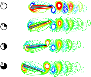
  $y$-component of the hydrodynamic force applied on the foil surface. The pivot point of the pitching foil moves downwards when the foil is pitching upwards, and vice versa, as shown in figure 4(f). Consequently, the leading-edge vortex (LEV) of the pitching foil has the same sense of rotation as that of the trailing-edge vortex (TEV) of the pitching foil, as shown in figure 4(g).

Figure 4. (a) The trajectory of the pivot point of the pitching foil. Cycle-averaged (b) longitudinal speed and (c) lateral speed. Time histories of (d) longitudinal speed, (e) lateral speed and (f) lateral position of the pivot point of the pitching foil. (g) The instantaneous vorticity contours for the pitching foil in the case of (  $f=1.0,\ \theta _m=20^{\circ }$). Time histories of (h) thrust and (i) lateral force of the unconstrained foil (
 $F_T,\ F_y$) and tethered foil (
 $F_{T1},\ F_{y1}$). (j) The instantaneous vorticity contours for the tethered foil in the case of (
  $f=1.0,\ \theta _m=20^{\circ }$).
It should be pointed out that, for the ranges of pitching frequency and amplitude considered in this study, the unconstrained foil always can keep self-propelling in a straight line (the yaw angle of a single foil is much smaller than one degree). Meanwhile, the symmetry breaking of the reverse von Kármán wake, as well as the persistent lateral drifting, has never been observed for the unconstrained foil in the current simulations. This is a surprising result, which is significantly different from that of the tethered flapping foil. For the tethered flapping foil, the symmetry breaking of the reverse von Kármán wake occurs when the flapping frequency is high (Godoy-Diana et al. Reference Godoy-Diana, Marais, Aider and Wesfreid2009). As a result, the net lateral force can be generated by the foil (Cleaver, Wang & Gursul Reference Cleaver, Wang and Gursul2012), which means that lateral drifting could occur. As shown in figure 4(h–j), for example, for the tethered foil in the case of ( $Re=200,\ f=1.0,\ \theta _m=20^{\circ }$), its wake is deflected significantly, and the cycle-averaged thrust and lateral force are, respectively,
  $\bar {F}_{T1}=0.15$ and
  $\bar {F}_{y1}=-2.6$. However, for the unconstrained foil with the same parameters, the wake is not deflected, as shown in figure 4(g). Moreover, because of the force balance during the steady propulsion, both the cycle-averaged thrust and the lateral force of the unconstrained foil are zero during cruising, as shown by the black line in figure 4(h,i), for example. It seems that the unconstrained foil can successfully avoid the symmetry breaking of the wake. The reason may be that the passive lateral oscillation of the unconstrained foil can suppress the formation of the dipolar vortex structure, which is crucial for the wake deflection of the flapping foil (Godoy-Diana et al. Reference Godoy-Diana, Marais, Aider and Wesfreid2009).
The cycle-averaged longitudinal speed ( $\bar {u}_x$), power consumption (
 $\bar {P}$) and the lateral oscillating amplitude (
 $A_p$) of the pitching foil are, respectively, calculated, as shown in figure 5(a–c). From figure 5(a), it is clear that
  $\bar {u}_x$ increases with the increase of both pitching amplitude and pitching frequency. The same variation trend can be observed for
  $\bar {P}$, as shown in figure 5(b). However,
  $A_p$ only increases with the pitching amplitude and shows slight variation when the pitching frequency changes, as plotted in figure 5(c). Such variation of
  $A_p$ can be explained as follows. The lateral oscillating amplitude of the pitching foil can be approximately calculated as
  $A_p=0.5T \, \bar {u}_{yd}$, where
  $\bar {u}_{yd}$ is the averaged lateral speed of the foil in one stroke (such as the downstroke, as shown in figure 4e,f). For a given pitching frequency,
  $\bar {u}_{yd}$ increases significantly with the increase of
  $\theta _m$, and then
  $A_p$ increases with
  $\theta _m$. For instance, the values of
  $\bar {u}_{yd}$ in the cases of (
  $f=2.0,\ \theta _m=10^{\circ }$) and (
  $f=2.0,\ \theta _m=20^{\circ }$) are, respectively,
  $\bar {u}_{yd}=0.61$ and
  $\bar {u}_{yd}=1.25$. Thus, there are
  $A_p \approx 0.15$ and
  $0.31$, respectively, in the cases of (
  $f=2.0,\ \theta _m=10^{\circ }$) and (
  $f=2.0,\ \theta _m=20^{\circ }$). For a given
  $\theta _m$, although
  $\bar {u}_{yd}$ increases with the increase of
  $f$,
$f$,  $A_p$ changes slightly since
  $T$ is decreased. For example,
  $\bar {u}_{yd}=0.62$ and
  $1.25$, respectively, in the cases of (
  $f=1.0,\ \theta _m=20^{\circ }$) and (
  $f=2.0,\ \theta _m=20^{\circ }$), but
  $A_p \approx 0.31$ in both cases. Therefore,
  $A_p$ increases with
  $\theta _m$, but changes slightly with
  $f$.
$f$.

Figure 5. Cycle-averaged (a) longitudinal speed, (b) power consumption and (c) lateral oscillating amplitude of the pitching foil with different values of pitching frequency and amplitude. The relationship between (d) the longitudinal propulsive Reynolds number, (e) the power consumption and (f) the passive oscillating Reynolds number and the flapping Reynolds number.
In order to further analyse the hydrodynamic performance of the unconstrained pitching foil, three non-dimensional parameters are defined: the flapping Reynolds number is defined as  $Re_f=fAc/\nu$, where
  $A=2 \times 0.95 \sin (\theta _m)$; the propulsive Reynolds number in the longitudinal direction is defined as
  $Re_{ux}=\bar {u}_xc/\nu$; and the passive oscillating Reynolds number is defined as
  $Re_p=fA_pc/\nu$.
Surprisingly, as can be seen from figure 5(d–f), there exist some simple scaling laws for these non-dimensional parameters. First,  $Re_{ux}$ increases monotonically with
  $Re_f$, which can be approximately described as
  $Re_{ux} \sim Re_f^{5/3}$, as shown in figure 5(d). The accurate mechanism of the scaling law
  $Re_{ux} \sim Re_f^{5/3}$ is still unknown so far. Inspired by the work of Gazzola et al. (Reference Gazzola, Argentina and Mahadevan2014), one possible physical interpretation of
  $Re_{ux} \sim Re_f^{5/3}$ is described as follows. In one pitching stroke (such as downstroke), the mass of flow pushed by the pitching foil per unit length can be scaled as
  $m \sim \rho {\rm \pi}c^{2} \times 2\theta _m/(2{\rm \pi} ) \sim c^{2}\theta _m$. On the other hand, the acceleration of the surrounding flow can be scaled as
  $a \sim cf^{2}\theta _m$. Thus, the hydrodynamic force on the foil can be scaled as
  $F=ma \sim c^{2}\theta _m \times cf^{2}\theta _m=f^{2}c^{3}{\theta _m}^{2}$. Considering one pitching angle, the thrust of the foil can be scaled as
  $F_T=F \sin (\theta _m) \sim f^{2}c^{3}{\theta _m}^{2} \sin (\theta _m)$. For a small pitching amplitude, one has
  $\theta _m \approx \sin (\theta _m)$. Thus, the thrust can be scaled as
  $F_T \sim f^{2}(c \sin (\theta _m))^{3} \sim f^{2}A^{3}$. On the other hand, the drag of the foil in the laminar flow can be scaled as
  $D \sim u_x^{3/2}$ (Gazzola et al. Reference Gazzola, Argentina and Mahadevan2014). Balancing the thrust and drag, then
  $f^{2}A^{3} \sim u_x^{3/2}$. When the values of the two dimensionless variables
  $f$ and
  $A$ are close to each other, one has
  $f^{2}A^{3} \approx (\,fA)^{5/2}$. Consequently, it holds that
  ${u_x}^{3/2} \sim (\,fA)^{5/2}$, i.e.
  $u_x \sim (\,fA)^{5/3}$. Namely, one has
  $Re_{ux} \sim Re_f^{5/3}$.
It should be noted that the simple scaling law here is different from that proposed in the previous study (Gazzola et al. Reference Gazzola, Argentina and Mahadevan2014), i.e.  $Re_{ux} \sim Re_f^{4/3}$. As shown in figure 6(a), it can be seen that the current simple scaling law
  $Re_{ux} \sim Re_f^{5/3}$ is not applicable to the numerical results in the previous study (Gazzola et al. Reference Gazzola, Argentina and Mahadevan2014). However, it should be emphasized that the current simple scaling law is applicable to the results from other previous studies (Alben & Shelley Reference Alben and Shelley2005; Hu & Xiao Reference Hu and Xiao2014). As reported in Gazzola et al. (Reference Gazzola, Argentina and Mahadevan2014), the scaling law
  $Re_{ux} \sim Re_f^{4/3}$ is applicable to the performance of many species. However, it can be seen from the supplementary information of Gazzola et al. (Reference Gazzola, Argentina and Mahadevan2014) that the scaling law
  $Re_{ux} \sim Re_f^{4/3}$ is satisfied only roughly for some species, such as Florida manatee, American alligator and larval zebrafish. Interestingly, the data for these species are in good agreement with the current scaling law
  $Re_{ux} \sim Re_f^{5/3}$, as shown in figure 6(b,c). It is surprising that the present scaling law
  $Re_{ux} \sim Re_f^{5/3}$ is applicable to the locomotion of several aquatic swimmers in the region of
  $Re_{f} \sim O(10^{2})\text {--}O(10^{7})$. However, the reason why the locomotion of different species obeys different scaling laws is still unknown. It is believed that the prediction region, which is determined by
  $Re_{ux} \sim Re_f^{5/3}$ and
  $Re_{ux} \sim Re_f^{4/3}$, may be useful to predict the performance of flapping-based propulsion before a more universal scaling law is proposed.

Figure 6. Evidence for the scaling law  $Re_{ux} \sim Re_f^{5/3}$ from (a) the previous numerical studies and (b,c) the biological swimming behaviour in Nature. The data in panel (a) are extracted from figure 13(a) in Hu & Xiao (Reference Hu and Xiao2014), figure 2 in Alben & Shelley (Reference Alben and Shelley2005) and figure 3(a) in Gazzola et al. (Reference Gazzola, Argentina and Mahadevan2014). The data in panels (b) and (c) are extracted from figures S4(c,d), S5(a), S6(d), S8(c,d) and S10 in the supplementary information of Gazzola et al. (Reference Gazzola, Argentina and Mahadevan2014).
On the other hand, a similar variation trend can be observed for the power consumption (as shown in figure 5e), in which the relationship can be approximately described as  $\bar {P} \sim Re_f^{3}$. Furthermore, for the passive oscillation in the lateral direction,
  $Re_p$ can increase linearly with
  $Re_f$, which can be approximately described as
  $Re_p \sim Re_f$ and shown in figure 5(f). These simple scaling laws may be useful for predicting the performance of the flapping swimmer and designing micro aerial/underwater robots. The universality of such scaling laws will be discussed in the following section.
3.2. Effects of mass ratio and thickness–chord ratio
In this section, the effects of mass ratio and thickness–chord ratio on the propulsion of an unconstrained pitching foil are checked. Firstly, when the mass ratio varies, the pitching frequency and amplitude are, respectively, chosen as  $f=2.0$ and
  $\theta _m=10^{\circ }$, and the thickness–chord ratio is still
  $b/c=0.1$. As shown in figure 7(a,b), it is clear that
  $\bar {u}_x$ becomes a constant and
  $\bar {u}_y$ remains approximately zero after several periods. Namely, foils with different
  $\bar {m}$ can still achieve self-propulsion in a straight line, as shown in figure 7(c). Moreover, it can be seen that
  $\bar {u}_x$ significantly increases with
  $\bar {m}$. Meanwhile,
  $\bar {P}$ also increases with
  $\bar {m}$, as shown in figure 7(d). Furthermore, it can be seen from figure 7(a) that the heavier foil takes a greater number of strokes to reach steady propulsion. For example, the number of strokes that the foil takes to reach
  $98\,\%$ of its cruising speed is increased from 22 to 54 as
  $\bar {m}$ is increased from 1 to 40. This occurs because the heavier foil is less susceptible to fluid–structure interaction as compared with the lighter foil (Arora et al. Reference Arora, Gupta, Sanghi, Aono and Shyy2016). In addition, it can be seen from figure 7(b) that
  $\bar {u}_y$ of the heavier foil varies more dramatically than that of the lighter foil during the transition. As a result, the heavier foil has a larger displacement in the lateral direction before steady propulsion is achieved, as compared with that of the lighter foil, as shown in figure 7(c). Nevertheless, it is noticed that the undulation of the trajectory (which can be represented by using
  $A_p$) of the heavier foil is smaller than that of the lighter foil, as shown in figure 7(e).

Figure 7. The cycle-averaged propulsive speed in (a) longitudinal and (b) lateral directions, and (c) the trajectory of the pivot point of the pitching foil in the case of (  $f=2.0,\ \theta _m=10^{\circ }$). The cycle-averaged (d) power consumption and (e) the lateral oscillating amplitude as functions of mass ratio. The open black arrows in panel (c) indicate which one of x-axes is the reference coordinate of the trajectory.
Additionally, the effect of the thickness–chord ratio of the foil on the self-propulsion is also studied in the current work. Again, the parameters  $\bar {m}=1$,
  $f=2.0$ and
  $\theta _m=10^{\circ }$ are used. As shown in figure 8(a), it can be seen that
  $\bar {u}_x$ greatly decreases with
  $b/c$. A similar observation can be found in the previous work (Zhang et al. Reference Zhang, Pan, Chao and Zhang2018). In addition, there is a threshold value of
  $b/c$ above which the propulsive direction is reversed. In the current work, such a threshold value is approximately
  $b/c=0.3 \sim 0.4$. This is consistent with the previous finding (Ashraf et al. Reference Ashraf, Young and Lai2011), which shows that the flapping foil could generate a negative thrust when its thickness is larger than approximately 30% of the chord length. Meanwhile, it can be found from figure 8(b) that
  $\bar {u}_y$ still remains approximately zero when
  $b/c$ varies. Namely, the foils with various
  $b/c$ can still achieve self-propulsion in a straight line. On the other hand,
  $A_p$ and
  $\bar {P}$, respectively, decreases and increases slightly with
  $b/c$, as shown in figure 8(c,d). Consequently, it seems that the thinner foil is a better recommendation than the thicker foil for flapping-wing propulsion.

Figure 8. The cycle-averaged propulsive speed in (a) longitudinal and (b) lateral directions in the case of (  $f=2.0,\ \theta _m=10^{\circ }$). The cycle-averaged (c) lateral oscillating amplitude and (d) power consumption of the pitching foil as functions of thickness–chord ratio.
In order to examine whether the scaling laws proposed above are affected by the mass ratio and thickness–chord ratio, the cases of (  $f=1.0,\ \theta _m=15^{\circ }$ and
  $25^{\circ }$), (
  $f=1.5,\ \theta _m=20^{\circ }$) and (
  $f=2.0,\ \theta _m=10^{\circ },\ 20^{\circ }$ and
  $25^{\circ }$) are studied. From the results illustrated in figure 9, it is obvious that these scaling laws, i.e.
  $Re_{ux} \sim Re_f^{5/3}$,
  $\bar {P} \sim Re_f^{3}$ and
  $Re_p \sim Re_f$, are still applicable to flapping foils with different values of the mass ratio and thickness–chord ratio. It can be seen that these scaling laws are independent of the mass and thickness of the flapping foil.

Figure 9. The relationship between (a) the longitudinal propulsive Reynolds number, (b) the power consumption and (c) the passive oscillating Reynolds number and the flapping Reynolds number for various mass ratios and thickness–chord ratios.
4. Conclusions
In summary, the performance of an unconstrained flapping foil, which can self-propel in both the longitudinal and lateral directions, is numerically studied in this paper. It is found that, for the parameters considered here, the pitching foil can self-propel in a straight line along the longitudinal direction, together with a passive oscillation in the lateral direction. When the pitching amplitude (or pitching frequency or mass ratio) increases, the mean longitudinal speed of the pitching foil is significantly enhanced, but more power is consumed. But when the thickness–chord ratio increases, the longitudinal speed of the pitching foil is significantly reduced, and more power consumption is required. On the other hand, it is identified that the propulsive speed, the power consumption and the lateral oscillating motion of an unconstrained flapping foil can obey some simple scaling laws. Specifically, the propulsive Reynolds number based on the longitudinal speed obeys the law  $Re_{ux} \sim Re_f^{5/3}$, the power consumption obeys the law
  $\bar {P} \sim Re_f^{3}$, and the lateral oscillating Reynolds number based on the oscillating amplitude obeys the law
  $Re_p \sim Re_f$. These simple scaling laws seem to be independent of the mass and thickness of the foil, and they may be useful for predicting the performance of flapping swimmers and designing micro aerial/underwater robots. However, it should be pointed out that the current conclusions are based on the performance of a two-dimensional foil at low Reynolds number. The effects of three dimensions and Reynolds number on the performance of an unconstrained flapping wing are neglected in this paper. Thus, the question whether these scaling laws are suitable for a three-dimensional flapping wing with low aspect ratio is unknown, and will be considered in future work.
Acknowledgements
J.W. acknowledges the support of the National Natural Science Foundation of China (grant no. 12072158) and the Research Fund of the State Key Laboratory of Mechanics and Control of Mechanical Structures (Nanjing University of Aeronautics and Astronautics) (grant no. MCMS-I-0120G02). X.L. acknowledges the support of the Funding for Outstanding Doctoral Dissertation of Nanjing University of Aeronautics and Astronautics (grant no. BCXJ19-02) and the Postgraduate Research & Practice Innovation Program of Jiangsu Province (grant no. KYCX19_0154). This work is also supported by the Priority Academic Program Development of Jiangsu Higher Education Institutions (PAPD).
Declaration of interests
The authors report no conflict of interest.


