


1. Introduction
Unsteady ground effect is exploited by some rays and flatfish to improve their cost of transport or cruising speed when swimming near the ocean floor or walls (Blake Reference Blake1983; Webb Reference Webb1993, Reference Webb2002; Nowroozi et al. Reference Nowroozi, Strother, Horton, Summers and Brainerd2009; Blevins & Lauder Reference Blevins and Lauder2013). There is a growing body of research characterizing unsteady ground effect through theory, numerics and experiments. Tanida (Reference Tanida2001) developed an analytical model for a fluttering plate in a bounded flow, and Iosilevskii (Reference Iosilevskii2008) investigated weak ground effect of a heaving wing, respectively. More experiments and numerical models have investigated unsteady ground effect for rigid (Quinn et al. Reference Quinn, Moored, Dewey and Smits2014c; Mivehchi, Dahl & Licht Reference Mivehchi, Dahl and Licht2016; Perkins et al. Reference Perkins, Elles, Badlissi, Mivehchi, Dahl and Licht2017) and flexible (Blevins & Lauder Reference Blevins and Lauder2013; Quinn, Lauder & Smits Reference Quinn, Lauder and Smits2014a; Fernández-Prats et al. Reference Fernández-Prats, Raspa, Thiria, Huera-Huarte and Godoy-Diana2015; Dai, He & Zhang Reference Dai, He and Zhang2016; Park, Kim & Sung Reference Park, Kim and Sung2017; Zhang, Huang & Lu Reference Zhang, Huang and Lu2017) oscillating foils and wings at moderate ground distances, which are biologically relevant distances and applicable for the design of bio-inspired devices. The collection of this work has concluded that unsteady ground effect improves thrust production with little or no change in the efficiency. Additionally, Kurt et al. (Reference Kurt, Cochran-Carney, Zhong, Mivehchi, Quinn and Moored2019) reported the presence of a stable equilibrium altitude for a freely swimming pitching foil in the presence of a ground plane that was previously observed in the lift force of constrained flapping foils both experimentally (Mivehchi et al. Reference Mivehchi, Dahl and Licht2016; Perkins et al. Reference Perkins, Elles, Badlissi, Mivehchi, Dahl and Licht2017), and numerically (Quinn et al. Reference Quinn, Moored, Dewey and Smits2014c; Kim et al. Reference Kim, Park, Huang and Sung2017). Furthermore, they propose a thrust enhancement of up to 17 % with a less than 2 % enhancement in the efficiency of a purely pitching foil at its equilibrium altitude.
To understand the origins of thrust and efficiency in unsteady ground effect, we can rely on scaling laws. The basis of many recent scaling laws lies in classic unsteady linear theory. The theories of Theodorsen (Reference Theodorsen1935, pp. 413–433), Garrick (Reference Garrick1936, pp. 419–427) and von Kármán & Sears (Reference von Kármán and Sears1938) have become particularly useful in this pursuit due to their clear assumptions (incompressible and inviscid flow, small-amplitude motions, non-deforming, and planar wakes) and the identification of the physical origins of their terms. For instance, these theories decompose the forces acting on unsteady foils into three types: added mass, quasi-steady and wake-induced forces. Theodorsen's theory was extended by Garrick (Reference Garrick1936, pp. 419–427) by accounting for the singularity in the vorticity distribution at the leading edge to determine the thrust force produced and the power required by such motions. By following Garrick (Reference Garrick1936, pp. 419–427), Dewey et al. (Reference Dewey, Boschitsch, Moored, Stone and Smits2013), Quinn, Lauder & Smits (Reference Quinn, Lauder and Smits2014b) and Quinn et al. (Reference Quinn, Moored, Dewey and Smits2014c) scaled the thrust forces of pitching and heaving flexible panels with their added mass forces. Moored & Quinn (Reference Moored and Quinn2018) advanced this previous work by considering the circulatory and added mass forces of self-propelled pitching foils as well as wake-induced nonlinearities that are not accounted for in classical linear theory (Garrick Reference Garrick1936, pp. 419–427). It was shown that data generated from a potential flow solver and from experimental measurements (Ayancik et al. Reference Ayancik, Zhong, Quinn, Brandes, Bart-Smith and Moored2019) were in excellent agreement with the proposed scaling laws. Similarly, Floryan et al. (Reference Floryan, Van Buren, Rowley and Smits2017) considered both the circulatory and added mass forces and showed excellent collapse of experimental data with their scaling laws for the thrust and power of a heaving or pitching two-dimensional rigid foil. While these studies have provided great insights into the origins of unsteady force production, they were limited to isolated propulsors.
Here, we advanced the scaling laws for isolated purely pitching propulsors developed by Moored & Quinn (Reference Moored and Quinn2018) to account for the proximity to the ground. These scaling laws provide new insight into the underlying physics of unsteady ground effect and are verified through simulations and experiments. Furthermore, we show that the added mass forces of the core two-dimensional scaling relations (Moored & Quinn Reference Moored and Quinn2018) can be modified by accounting for the increase in the added mass of an object near a ground plane derived from classical hydrodynamic theory (Brennen Reference Brennen1982), and the circulatory forces can be modified by accounting for bound and wake vortex-body interactions in ground effect. The newly developed scaling laws offer a physical rationale for the origins of force production, power consumption and efficient unsteady swimming in proximity to the ground.
2. Methods
Potential flow simulations and water-channel experiments were conducted on hydrofoils in and out of ground effect. The details of the hydrofoil geometry and kinematics, as well as the numerical and experiment methods employed, are given below.
2.1. Hydrofoil geometry and kinematics
The hydrofoils used throughout this study have a rectangular planform shape, either a 10 % or 7 % thick (see §§ 2.2 and 2.3 for more details) tear-drop cross-section (Quinn et al. Reference Quinn, Moored, Dewey and Smits2014c) with a chord length of  $c=0.095$ m and an effectively infinite aspect ratio. The hydrofoils were actuated with sinusoidal purely pitching motions about their leading edge of
  ${\theta }(t)={\theta }_0\sin (2{\rm \pi} f t)$, where
  $\theta _0$ is the pitching amplitude,
  $f$ is the frequency and
  $t$ is the time. Here, the reduced frequency can be defined as,
  $k \equiv f c/U$, and the Strouhal number,
  $St \equiv f A/U$, where
  $U$ is the free-stream speed and
  $A$ is the peak-to-peak amplitude of motion, that is,
  $A = 2c \sin \theta _0$. The amplitude of motion is reported in its dimensionless form as
  $A^{*} = A/c$ and the dimensionless ground distance is reported as
  $D^{*} = D/c$, where
  $D$ is the distance from the leading edge of the foil to the ground plane. The input variables used are summarized in table 1.
Table 1. Numerical and experimental variables and parameters. The aspect ratio is ![]() where s is the span length of a hydrofoil, and the Reynolds number is
where s is the span length of a hydrofoil, and the Reynolds number is  $Re = Uc/\nu$ where
  $\nu$ is the kinematic viscosity. The first experiments were performed at the University of Virginia (UVA), while the second experiments were performed at Lehigh University (Lehigh U.).

For the experiments and the simulations, the time-averaged thrust and power coefficients can be non-dimensionalized by the added mass forces and added mass power from small-amplitude theory (Garrick Reference Garrick1936, pp. 419–427) or by dynamic pressure:
 \begin{align} C_T \equiv \frac{\bar{T}}{\rho S_p f^{2} A^{2}}, \quad C_P \equiv \frac{\bar{P}}{\rho S_p f^{2} A^{2} {U}},\quad C^{dyn}_T \equiv \frac{\bar{T}}{1/2 \rho S_p U^{2}}, \quad C^{dyn}_P \equiv \frac{\bar{P}}{1/2 \rho S_p U^{3}}, \end{align}
 where  $\rho$ is the density of the fluid medium,
  $S_p$ is the propulsor planform area,
  $\bar{T}$ is the mean thrust,
  $\bar{P}$ is the mean power, and the two normalizations are related through the Strouhal number by simple transformations:
  $C_T^{dyn} = C_T\, (2 St^{2})$ and
  $C_P^{dyn} = C_P \, (2 St^{2})$. The propulsive efficiency can be defined as
  $\eta \equiv C_T/C_P\equiv C_T^{dyn}/C_P^{dyn}$.
2.2. Numerical method
To measure the foil's hydrodynamic performance in unsteady ground effect, we used a two-dimensional boundary element method (BEM) based on potential flow theory where the flow is assumed to be irrotational, incompressible and inviscid. A 10 % thick tear-drop cross-section was simulated. The potential flow problem reduces to finding the perturbation potential that satisfies Laplace's equation. This is accomplished by distributing source and doublet elements over the body surface and doublet elements over the wake surface. A no-flux boundary condition is satisfied on the body surface, an explicit Kutta condition is applied at the trailing edge (zero vorticity at the trailing edge), the wake element strengths satisfy Kelvin's condition, and the wake elements are deformed with the local velocity through a desingularized Biot–Savart law (Krasny Reference Krasny1986). The presence of the ground is modelled using the method of images, which automatically satisfies the no-flux boundary condition on the ground plane. Finally, the foil's forces are determined by integrating the pressure acting on the foil via the unsteady Bernoulli equation. For more details on the numerical method see Moored (Reference Moored2018) and Moored & Quinn (Reference Moored and Quinn2018).
Convergence studies found that the thrust and efficiency time-averaged over the tenth cycle changes by less than 2 % when the number of body panels,  $N_{b}= 150$, and the number of time steps per cycle,
  $N_t= 150$, were doubled independently. The current study considered the foil's cycle-averaged thrust and efficiency as convergence metrics since these are the prime output variables of interest. The computations were run over 10 flapping cycles and the time-averaged data are obtained by averaging the last cycle. For all simulations there was less then 1 % change in the thrust and efficiency after seven flapping cycles.
2.3. Experimental methods
New experiments (EXP1) were conducted in a closed-loop water channel (Rolling Hills 1520) at the UVA with a foil of aspect ratio 3, a 10 % thick tear-drop cross-section, and a chord-based Reynolds number of 13 500. A nominally two-dimensional flow was achieved by installing a horizontal splitter plate and a surface plate near the tips of the hydrofoil (figure 1b). The gap between the hydrofoil tips and the surface/splitter plate was less than 5 mm. Surface waves were also minimized by the presence of the surface plate. An additional splitter plate was used instead of a tunnel sidewall to control the boundary-layer thickness. A boundary-layer thickness of  $\delta _{99\,\%} \approx 7.5$ mm (
 $\delta _{99\,\%}/c = 0.08$) was measured using particle image velocimetry at the position aligned with the leading edge of the hydrofoil. A high-torque digital servo motor (Dynamixel MX64) drove a stainless steel driveshaft (
 $6.35$ mm diameter) pitching the hydrofoil about its leading edge with a prescribed pitching motion described in § 2.1. The output angle was verified by an absolute encoder (US Digital A2K 4096 CPR). Eight Strouhal numbers were considered in the range
  $0.18 \leq St \leq 0.44$, five pitching amplitudes in the range
  $7\,^{\circ } \leq \theta _0 \leq 15\,^{\circ }$, and thirteen dimensionless ground distances in the range
  $0.24 \leq D^{*} \leq 1.66$. Thus, the dimensionless distance from the far sidewall of the water channel was greater than or equal to
  $2$. Each trial was repeated three times. The forces and moments were measured with a six-axis force-torque sensor (ATI-Mini 40: SI-40-2). Then the streamwise forces were time-averaged over 20 oscillation cycles to determine the net thrust,
  $\bar {T}$. The time-averaged power, defined as
  $\bar {P} = \bar {\tau _z \dot {\theta }}$ where
  $\tau _z$ is the pitching moment and
  $\dot {\theta }$ is the pitching velocity, was also measured.

Figure 1. Schematic of (a) the constrained pitching hydrofoil apparatus at Lehigh University (Kurt et al. Reference Kurt, Cochran-Carney, Zhong, Mivehchi, Quinn and Moored2019), and (b) the constrained hydrofoil apparatus at the UVA.
A second (EXP2) previously published experimental data set (Kurt et al. Reference Kurt, Cochran-Carney, Zhong, Mivehchi, Quinn and Moored2019) is also used for further validation of the proposed scaling laws. Force measurements were conducted in a recirculating water channel located at Lehigh University with a test section that is  $4.9$ m long,
  $0.93$ m wide and
  $0.61$ m deep. The hydrofoil used in these experiments had a rectangular planform shape, a 7 % thick tear-drop cross-section with an aspect ratio of 2, and a chord-based Reynolds number of 9000. In order to obtain a nominally two-dimensional flow, a splitter and a surface plate were installed to prevent flow around the foil tips (figure 1a). An additional vertically oriented splitter plate was also installed on the side of the channel to act as the ground wall. The hydrofoil was pitched about an axis that was
  $3$ mm (
 $\approx$3 % of the chord) behind its leading edge by a servo motor (Dynamixel MX-64AT). An incremental rotary encoder (US Digital E5) was used to track the angular position of the foil throughout the prescribed motion defined in § 2.1. Three flapping frequencies,
  $f=0.5$,
  $0.75$ and
  $1$ Hz, and five dimensionless amplitudes,
  $A^{*} = 0.125$,
  $0.25$,
  $0.38$,
  $0.49$ and
  $0.61$, were considered. The combination of these kinematic variables resulted in a Strouhal range of
  $0.26 \leq St \leq 0.63$. Additionally, the dimensionless ground distance was varied within the range of
  $0.25 \leq D^{*} \leq 2.6$, where the distance between the foil and the far sidewall of the channel was greater than or equal to six chord lengths. Net thrust and pitching moment were measured from the foil by using a six-axis force sensor (ATI Nano43). The power was measured in the same way as in EXP1. The thrust and power were then time-averaged over
  $100$ oscillation cycles. Each experiment was repeated five times, and the reported data points were calculated as the mean of the time-averaged values from these five trials.
Two experimental data sets were used in this study for two reasons: (1) when combined together the data sets cover a wide range of Strouhal numbers,  $0.18 \leq St \leq 0.63$, nearly matching the range of the simulations, and (2) showing collapse of the data from two experiments done in different facilities, at different
  $Re$, and with different cross-sectional shapes highlights the robustness of the scaling laws and their reliance on the underlying physics. All of the parameters and ranges of variables for both EXP1 and EXP2 can be found in table 1.
3. Scaling laws for a pitching foil in ground effect
Moored & Quinn (Reference Moored and Quinn2018) introduced scaling relations for the performance of two-dimensional, self-propelled pitching hydrofoils. Here, we will briefly review these scaling laws since they will serve as the basis with which to apply novel modifications to the added mass and circulatory forces to account for the proximity to the ground.
3.1. Scaling laws of an isolated swimmer
Moored & Quinn (Reference Moored and Quinn2018) developed thrust and power scaling laws as a combination of the added mass and circulatory forces from classical linear theory (Garrick Reference Garrick1936, pp. 419–427) with additional nonlinear terms that are not accounted for in linear theory. For instance, the thrust coefficient defined in (2.1a–d) is proposed to be proportional to the superposition of three terms
 \begin{equation} C_T = c'_1+ c'_2\phi_2 + c'_3\phi_3 \end{equation}
with
 \begin{equation} \phi_2 ={-}\left[\frac{3F}{2}+\frac{F}{{\rm \pi}^{2} k^{2}}-\frac{G}{2{\rm \pi} k}-( F^{2}+G^{2}) \left(\frac{1}{{\rm \pi}^{2} k^{2}} + \frac{9}{4} \right) \right],\quad \phi_3=A^{*}, \end{equation}
where  $c'_1$,
  $c'_2$ and
  $c'_3$ are constants, and
  $F$ and
  $G$ are the real and imaginary components of Theodorsen's lift deficiency function, respectively (Theodorsen Reference Theodorsen1935, pp. 413–433). The first and second terms represented by
  $c'_1$ and
  $c'_2 \phi _2$ are the added mass and circulatory thrust forces, respectively, from linear theory, while the third term represented by
  $c'_3 \phi _3$ is not accounted for in linear theory. The third term corresponds to a form drag that is proportional to the time-varying projected frontal area of the foil that occurs during large-amplitude pitching oscillations, and is not present in linear theory due to a small-amplitude assumption. Moored & Quinn (Reference Moored and Quinn2018) also proposed that the power coefficient defined in (2.1a–d) is a linear superposition of three terms:
 \begin{equation} C_P = c'_4+ c'_5\phi_5 + c'_6\phi_6 \quad\text{with:}\ \phi_5 = \frac{St^{2}}{k}\left(\frac{k^{*}}{1+k^{*}}\right),\quad \phi_6=St^{2}k^{*}, \end{equation}
where  $c'_4$,
  $c'_5$ and
  $c'_6$ are arbitrary constants, and
  $k^{*}=k/(1+4St^{2})$. The first term (
 $c'_4$) is the added mass power from linear theory. The second term
  $(c'_5 \phi _5)$ is a power term that is not present in linear theory and develops from the
  $x$-component of velocity of a pitching propulsor, which is neglected in linear theory due to the small-amplitude assumption. For large-amplitude motions, this velocity does not disappear, leading to an additional velocity component acting on the bound vorticity of the propulsor and creating an additional contribution to the generalized Kutta–Joukowski force also known as the vortex force (Saffman 1992). The third term
  $(c'_6 \phi _6)$ is also a power term that is absent in linear theory and develops during wake deformation when the trailing-edge vortices are no longer planar as assumed in the theory. As a result, the proximity of the trailing-edge vortices induce a streamwise velocity over the foil and an additional contribution to the vortex force. In short, the second and third terms are described as the large-amplitude separating shear layer and vortex proximity power terms, respectively, and both terms are circulatory in nature. For more details on the development of the two-dimensional scaling relations see Moored & Quinn (Reference Moored and Quinn2018).
3.2. Scaling laws modifications for ground effect
In presence of the ground, it is postulated that the added mass (and thus, the added mass thrust and power terms), as well as the vortex proximity power term will be affected and act as the primary drivers for the observed scaling trends with ground proximity. These two modifications for a pitching foil are described below.
The close proximity of a solid boundary can cause a substantial increase in the added mass of a pitching foil. This is due to the increase in fluid acceleration between the foil and boundary (Brennen Reference Brennen1982). Classic hydrodynamic theory shows that for a circular cylinder with radius  $r$ moving with a distance
  $d$ from a solid boundary (when
  ${d}/{r}<1$), the added mass increases as the cylinder moves closer to the boundary. In this case, the added mass can be represented as the addition of the isolated added mass with an additional added mass due to the acceleration of flow in the presence of a solid boundary as
 \begin{equation} M_a={\rm \pi}\rho r^{2} \left[1 +\sum_{j=1}^{\infty} \frac{1}{2^{2j-1}}\left(\frac{r}{d}\right)^{2j}\right]. \end{equation}
 When a thin foil is far from a boundary and it pitches about its leading edge, the added mass resisting the angular acceleration is precisely equal to that of a translating cylinder when the characteristic acceleration of the foil is taken as the acceleration normal to the midchord of the foil. Moreover, by using the Joukowsky conformal map, the radius of a cylinder,  $r$, far from a boundary, may be mapped to the chord length of a thin foil as
  $c=4r$. Consequently, we postulate that these two features will approximately hold true as a pitching foil approaches a boundary such that the scaling of the added mass can be determined from (3.3) with
  $c=4r$. Therefore, we postulate that the added mass scales as
  $M_a \propto \sum _{j=0}^{\infty } c_j({1}/{D^{*}})^{2j}$; however, we will verify this proposed scaling with potential flow simulations. Furthermore, since the dimensionless distance of the foil to the ground is limited by the maximum trailing-edge amplitude, we neglect the effect of higher order terms of the series and assume the additional added mass contribution scales as the inverse of the dimensionless distance squared and its coefficient is to be determined. For extreme ground-effect problems, the higher order terms in the series are required. The added mass terms of (3.1) and (3.2) can then be modified to
 \begin{equation} c'_1=c_1+c_2\zeta_2, \quad c'_4=c_5+c_6\zeta_6 \end{equation}
where the  $\zeta _2=\zeta _6=(1/D^{*})^{2}$ are the additional added mass contributions to the thrust and power generation and the coefficients
  $c_1$,
  $c_2$,
  $c_5$, and
  $c_6$ are to be determined by minimizing the squared residuals.
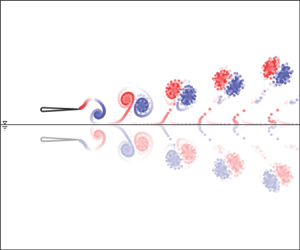
The second mechanism that significantly affects the power generation of a pitching foil in proximity to the ground is circulatory in nature and is best explained using the method of images, where each shedding vortex has an oppositely signed image vortex in the ground (see figure 2a). The image vortex of the near-ground negatively signed vortex induces an additional velocity at the trailing edge of the foil (see figure 2b) that acts to reduce the effect of the near-ground vortex and needs to be accounted for in the vortex proximity term in (3.2). The power contribution due to the proximity of the vortex is proportional to the additional lift generated from the streamwise induced velocity as  $L_{Prox}\approx \rho s u_{ind} \varGamma _{w}$ based on the Kutta–Joukowski theorem. The image vortex modifies this induced streamwise velocity at the trailing edge as
 \begin{equation} u_{ind}=\varGamma_w\frac{f}{U}\left[\overbrace{\frac{St}{1+4St^{2}}}^{\textit{Near-ground}\ v\textit{ortex}}-\overbrace{{2\frac{St+4kD^{*}}{1+4(4kD^{*}+St)^{2}}}}^{\textit{Image}\ v\textit{ortex}}\right], \end{equation}
where the advection speed of the vortex pair is  $U$ and the
  $\varGamma _w$ is the strength of the trailing-edge vortex circulation, which remains the same as proposed in Moored & Quinn (Reference Moored and Quinn2018). This induced streamwise velocity decreases with decreasing ground distance due to the near nullification of the induced velocity from the near-ground vortex by its image.

Figure 2. Effects of the image vortex system. (a) The down-stroke negatively signed vortex slows down due to the influence of its image vortex ( $l_u>l_d$). (b) The induced streamwise velocity of the shedding vortex,
  $u_{ind}$, and its image. The induced velocity,
  $\overrightarrow{V}_{ind}$, from the pair is smaller than a comparable isolated vortex.
The thrust circulatory term is also affected by this image vortex; however, the forces acting on purely pitching foils are dominated by added mass forces, and the circulatory modifications are not significant. The scaling laws for the thrust and power coefficient of a purely pitching foil in proximity to the ground are then
 \begin{equation} C_T= c_1+ \boldsymbol{c_2\zeta_2}+c_3\zeta_3+c_4\zeta_4, \quad C_P = c_5+ \boldsymbol{c_6\zeta_6}+c_7\zeta_7+\boldsymbol{c_8\zeta_8} \end{equation}
with
 \begin{align} \boldsymbol{\zeta_2}&=\boldsymbol{\zeta_6}=\boldsymbol{\frac{1}{{D^{*}}^{2}}}, \quad\zeta_3={-}\left[\frac{3F}{2}+\frac{F}{{\rm \pi}^{2} k^{2}}-\frac{G}{2{\rm \pi} k}-( F^{2}+G^{2}) \left(\frac{1}{{\rm \pi}^{2} k^{2}} + \frac{9}{4} \right) \right], \end{align}
 \begin{align} \zeta_4&=A^{*}, \quad \zeta_7=\frac{St^{2}}{k}\left(\frac{k^{*}}{1+k^{*}}\right), \quad \zeta_8 = St^{2}k^{*}-\boldsymbol{2k St\frac{(St-4kD^{*})}{1+4(St-4kD^{*})^{2}}}. \end{align}
 The coefficients  $c_3$,
  $c_4$,
  $c_7$, and
  $c_8$ are to be determined by minimizing the squared residuals. The added mass and circulatory ground-effect terms are highlighted with bold font and they vanish for large
  $D^{*}$. The scaling laws can also be written in terms of the thrust and power coefficients normalized by dynamic pressure as
 \begin{equation} C_T^{dyn} = 2St^{2}(c_1+ \boldsymbol{c_2\zeta_2}+c_3\zeta_3+c_4\zeta_4), \quad C_P^{dyn} = 2St^{2}(c_5+ \boldsymbol{c_6\zeta_6}+c_7\zeta_7+\boldsymbol{c_8\zeta_8}). \end{equation}
4. Results and discussion
The combination of computational input variables presented in table 1 leads to 665 two-dimensional simulations with a Strouhal number range of  $0.1 \leq St \leq 0.6$ and a reduced frequency range of
  $0.1 \leq k \leq 2.0$. From these simulations, the thrust and power coefficients as defined in (2.1a–d) are presented in figure 3. As in previous work (Quinn et al. Reference Quinn, Moored, Dewey and Smits2014c), thrust and power coefficients increase with amplitude and ground proximity (figure 3).

Figure 3. Coefficient of thrust and power as a function of reduced frequency from the self-propelled simulations. The marker colours going from black to white indicate  $D^{*}$ from far to close-ground cases, respectively, over the range of
  $0.3 \leq D^{*} \leq 2.0$. (a,c) Normalized based on dynamic pressure. (b,d) Normalized based on added mass forces.
Figure 4 presents the numerical data plotted as a function of the ground-effect scaling laws proposed in (3.6) and (3.7a,b).

Figure 4. Scaling of the (a) thrust and (b) power coefficients for all motion amplitudes and ground proximities considered in the numerical simulations.
An excellent collapse of the data is observed showing that the scaling laws capture the physics of unsteady ground effect in potential flows. The collapsed data can be seen to follow a line of slope one for both the thrust and power within  $\pm$2 % of the predicted scaling law. To achieve the collapse of the data, the equations for the thrust and power (3.6) are cast in a linear regression form and the coefficients are determined by minimizing the squared residuals using a gradient-descent-based algorithm. Two physically relevant conditions were enforced in the optimization algorithm: the added mass coefficients should always be positive, and the drag term in the thrust scaling should always be negative. The coefficients in the thrust law are determined to be
  $c_1 = 2.99$,
  $c_2 = 0.06$,
  $c_3 =-4.43$ and
  $c_4 = -0.09$, while for the power law they are
  $c_5 = 4.46$,
  $c_6 = 0.14$,
  $c_7 = 25.2$ and
  $c_8 = 14.13$. Note that the magnitude of each term in the scaling laws cannot be deduced from the magnitudes of the coefficients alone. The magnitude of an entire term must be considered since each term is formulated from various dimensionless variables of different orders. See § 4.1 for more details.
To validate whether the scaling laws can also apply to viscous flows, two experimental data sets are graphed against the scaling law predictions in figure 5. The first experimental data set (EXP1) shows a collapse of the data to within  $\pm 20\,\%$ (thrust and power) of the scaling-law prediction. The deviation of both thrust and power from the scaling-law prediction could be attributed to viscous effects, such as leading-edge separation, or from bending of the driving rod for the foil during high-frequency and high-amplitude motion, neither of which is accounted for in the scaling laws. The experimentally determined coefficients for the thrust are
  $c_1 = 5.03$,
  $c_2 = 0.08$,
  $c_3 = -5.72$ and
  $c_4 = -4.66$, and for the power they are
  $c_5 = 4.313$,
  $c_6 =0.004$,
  $c_7 = 0.11$ and
  $c_{8} = 30.91$. The second experimental data set (EXP2) shows a collapse within
  $\pm$23 % (thrust) and
  $\pm$12 % (power) of the scaling-law prediction. The experimentally determined coefficients for the thrust law are
  $c_1 = 4.29$,
  $c_2 = 0.09$,
  $c_3 = -14.33$ and
  $c_4 = -0.52$, and for the power law they are
  $c_5 = 8.26$,
  $c_6 = 0.03$,
  $c_7 = 33.06$ and
  $c_{8} = 15.38$.

Figure 5. Scaling of the time-averaged thrust and power for (a,b) UVA data set (EXP1) and (c,d) Lehigh University data set (EXP2) for all motion amplitudes and distances from the wall considered in experiments. The dashed lines present 20 % margins of error.
Our scaling relations show a good collapse of the data for a wide range of Reynolds number from  ${{Re}}=9000$ and
  ${{Re}} = 13\,600$ in the experiments, to
  $Re = \infty$ in the inviscid simulations. Here, it should be noted that the determined coefficients are different among the experimental and numerical data sets, which highlights that the coefficients likely vary with
  $Re$ as observed by Senturk & Smits (Reference Senturk and Smits2019). Although it is clear that the Reynolds number can alter the coefficients, no additional terms need to be introduced to account for data obtained at different
  $Re$. This supports the previous conclusion (Kurt et al. Reference Kurt, Cochran-Carney, Zhong, Mivehchi, Quinn and Moored2019) that the dominant flow physics in ground effect are inviscid in nature. The small differences between the scaling-law agreement in the experiments and the simulations may be attributed to secondary viscous effects.
The collapse of the data to a line of slope one for both numerical and experimental cases confirms that the newly proposed scaling laws capture the dominant flow physics of two-dimensional pitching propulsors in ground effect across a wide range of  $St$,
$St$,  $A^{*}$ and
  $D^{*}$.
4.1. Sensitivity of the scaling laws to the influence of the ground
Figure 6 shows the evolution of the scaling relations from the out-of-ground-effect scaling presented in Moored & Quinn (Reference Moored and Quinn2018) with the additions of the added mass and circulatory in-ground-effect corrections in the present work. The thrust and power coefficients are normalized by the added mass forces here to more clearly show the scaling variables’ sensitivity.

Figure 6. The influence of the proposed ground-effect terms on the scaling laws of a purely pitching foil using the numerical data. The dimensionless distance from the ground is mapped from white to black for the closest to the furthest proximity. Previous out-of-ground-effect scaling laws for the (a) thrust and (b) power coefficients (Moored & Quinn Reference Moored and Quinn2018). The addition of the ground-effect added mass correction only to the (c) thrust and (d) power coefficients. The addition of the ground-effect circulatory correction only to the (e) power coefficient. The bold terms on the figure labels are the terms examined in each case.
Figures 6(a) and 6(b) present the scaling of the thrust and power coefficients for the numerical simulations of a purely pitching foil in ground effect using the out-of-ground-effect scaling laws developed by Moored & Quinn (Reference Moored and Quinn2018). The dimensionless distance from the ground is mapped from white to black for the closest to the furthest proximity. As expected, the out-of-ground-effect scaling laws do not capture the thrust and power trends with variations in the ground distance. However, for a fixed ground distance, the previous scaling laws do show collapse of the thrust and power data to a straight line, indicating that the previous scaling laws can be used if the coefficients are determined for a foil in ground effect at that distance.
Figures 6c and 6(d) show the contribution of the in-ground-effect added mass amplification in the thrust ( $c_2\zeta _2$) and power (
 $c_6\zeta _6$) scalings without any modification to the circulatory terms. Figure 6(e), shows the in-ground-effect circulatory correction to the power (
 $c_8\zeta _8$) scaling without any modification to the added mass terms. To find the addition of both the in-ground-effect added mass and circulatory corrections see figure 4.
Figure 6(c) shows that only a ground-effect added mass correction to the thrust is necessary to achieve an excellent collapse of the data. Even though there is likely a circulatory correction to the thrust forces as well, it is not a significant contribution to the overall thrust forces. This is not surprising since it is known that a foil pitching about its leading edge is dominated by added mass thrust forces (Quinn et al. Reference Quinn, Moored, Dewey and Smits2014c; Floryan et al. Reference Floryan, Van Buren, Rowley and Smits2017; Moored & Quinn Reference Moored and Quinn2018). Figure 6(d) shows that the ground-effect added mass correction to the power provides a satisfactory collapse of the data for low-power coefficients, but tends to deviate from the scaling law at high-power coefficients. In contrast, figure 6(e) shows that the ground-effect circulatory correction provides a good collapse of the data for high-power coefficients while showing poor collapse for low-power coefficients. As seen in figure 4, the combination of both effects shows an excellent collapse of the data over the entire power coefficient range.
In order to understand the quantitative impact of the newly proposed ground-effect corrections on the thrust and power scaling laws, the magnitudes of entire terms must be compared, not just the magnitudes of their coefficients. For example, based on the numerical data the out-of-ground-effect added mass thrust has a fixed magnitude of  $c_1 = 2.99$, while the in-ground-effect added mass correction term varies based on the ground distance over the range of
  $0 \leq c_2\, \zeta _2 \leq 0.67$ resulting in the ground-effect correction accounting for up to 18 % of the total added mass thrust. Similarly, the ground-effect added mass power contributes up to 26 % of the total added mass power. The ground-effect circulatory correction contributes up to 96 % of the total vortex proximity term for the closest proximities examined. By examining the form of the circulatory correction, for fixed values of
  $k$ and
  $St$, it is observed that the image vortex effect scales like
  $1/D^{*}$, while the added mass ground effect scales like
  $1/(D^{*})^{2}$. This means that both effects decay as a swimmer moves away from a wall; however, the circulatory effect decays more slowly and is therefore a longer range effect than the added mass effect. This is further observed in the data where the ground-effect added mass contribution vanishes for
  $D^{*}>1$, while the ground-effect circulatory contribution vanishes for
  $D^{*}\gg 1$. In light of this analysis, combined heaving and pitching motions or purely heaving motions, where circulatory forces can be more important than added mass forces, may experience longer range ground-effect benefits.
5. Conclusion
New scaling laws are developed for the thrust generation and power consumption of two-dimensional pitching propulsors in ground effect by extending the two-dimensional pitching scaling laws introduced by Moored & Quinn (Reference Moored and Quinn2018) to consider added mass and circulatory effects due to the close proximity of a ground plane. The developed scaling laws are shown to predict inviscid numerical data and experimental data well, within  $\pm$20 % of the thrust and power data, respectively. The scaling laws reveal that both an increase in the added mass with decreasing ground distance and a reduction in the influence of a shed vortex by its image with decreasing ground distance are key physics to capture in a scaling law that is valid over a wide range of ground distances, motion amplitudes and Strouhal numbers. These results can be extended to two swimmers in side-by-side arrangements with an out-of-phase synchronization. The established scaling relationships elucidate the dominant flow physics behind the force production and energetics of pitching bio-propulsors and can be used to accelerate the design of bio-inspired devices that swim near a ground plane and operate in side-by-side schools.
Funding
This work was supported by the Office of Naval Research under Program Director Dr R. Brizzolara on MURI grant number N00014-08-1-0642 and BAA grant number N00014-18-1-2537, as well as by the National Science Foundation under Program Director Dr R. Joslin in Fluid Dynamics within CBET on NSF CAREER award number 1653181 and NSF collaboration award number 1921809.
Declaration of interests
The authors report no conflict of interest.


