


1. Introduction
Cylinders with rectangular or nearly rectangular cross-section are found in several engineering applications such as buildings, bridges and pylons (Tamura, Miyagi & Kitagishi Reference Tamura, Miyagi and Kitagishi1998). When placed in a uniform flow, bodies with short streamwise dimension, such as square cylinders or normal flat plates (Robichaux, Balachandar & Vanka Reference Robichaux, Balachandar and Vanka1999; Blackburn & Lopez Reference Blackburn and Lopez2003; Choi & Yang Reference Choi and Yang2014), produce a pair of shear layers, one for each side, which separate from the leading edge and roll up behind the cylinder to produce a von Kármán vortex street. For more elongated bodies, however, the flow is more complicated since shear layers separate from both the leading edge (LE) and the trailing edge (TE). For aspect ratios  ${A{\kern-4pt}R} \equiv L/D > 3$ (where
  $L$ and
  $D$ are the streamwise and cross-stream dimensions of the cylinder, respectively) after the LE separation the flow reattaches over the lateral side of the cylinder, before separating again at the TE. At large enough Reynolds number, vortex shedding occurs from both the LE and TE corners. When the Reynolds number
  $Re$ – defined with the unperturbed velocity
  $U_\infty$ and the cylinder thickness
  $D$ – is approximately
  $300$, the vortex shedding from LE and TE locks to the same frequency, and the Strouhal number
  $St \equiv f L / U_\infty$, which is a dimensionless measure of the shedding frequency
  $f$, increases in a stepwise manner with
  ${A{\kern-4pt}R}$. This is observed for several numerical and experimental studies for
  $Re$ up to
  $2000$: see for instance Okajima (Reference Okajima1982), Nakamura, Ohya & Tsuruta (Reference Nakamura, Ohya and Tsuruta1991), Ozono et al. (Reference Ozono, Ohya, Nakamura and Nakayama1992), Mills et al. (Reference Mills, Sheridan, Hourigan and Welsh1995) and Tan, Thompson & Hourigan (Reference Tan, Thompson and Hourigan1998).
Nakamura & Nakashima (Reference Nakamura and Nakashima1986) were first to invoke the impinging-shear-layer instability to explain the frequency locking and the stepwise variation of the Strouhal number with  $Re$. They also conjectured that, unlike for short blunt bodies or for bluff bodies without LE vortex shedding, this instability is a one-side phenomenon, and does not depend on the interaction between the shear layers separating from opposite sides. Indeed, for a rectangular cylinder with
  ${A{\kern-4pt}R} =5$, the instability mechanism and the shedding frequency were found to be unaffected by a splitter plate placed at the TE. Later, Naudascher & Rockwell (Reference Naudascher and Rockwell1994) coined the name impinging-LE-vortex (ILEV) instability to stress that, for long enough bodies, the vortices shed by the LE shear layer – and not the shear layer itself as predicted instead by the impinging-shear-layer instability – interact with the TE corners. Mills et al. (Reference Mills, Sheridan, Hourigan and Welsh1995) described the phenomenon within the more general framework of instability of impinging vorticity, in the form of both shear layer and discrete vortices. The ILEV instability is a resonant oscillation of the fluid. A periodic vortex shedding occurs from the LE shear layer. When a vortex passes over the TE, a pressure pulse is generated that travels upstream to trigger the shedding of a new LE vortex from the LE shear layer and, at the same time, a new TE vortex is shed in the wake. This process implies a link between the shedding frequency and the cylinder chord. The total number
  $n$ of LE vortices present on the side of the cylinder is an integer that varies with
  ${A{\kern-4pt}R}$: when the aspect ratio is very small,
  $n=0$; but when
  ${A{\kern-4pt}R} \approx 3$,
  $n=1$. By increasing
  ${A{\kern-4pt}R}$ further, the number of vortices that can be accommodated along the cylinder side grows in a quantised manner, leading to the stepwise variation of the shedding frequency, i.e.
  $St \approx U_c \cdot n$, where
  $U_c \approx 0.55 U_\infty$ denotes the mean convection velocity of a LE vortex, found to be approximately constant (Nakamura et al. Reference Nakamura, Ohya and Tsuruta1991; Mills, Sheridan & Hourigan Reference Mills, Sheridan and Hourigan2002; Tan, Thompson & Hourigan Reference Tan, Thompson and Hourigan2004).
To explain the stepwise dependence of  $St$ on
  ${A{\kern-4pt}R}$, Hourigan et al. (Reference Hourigan, Mills, Thompson, Sheridan, Dilin and Welsh1993) later followed by many others (Hourigan, Thompson & Tan Reference Hourigan, Thompson and Tan2001; Mills et al. Reference Mills, Sheridan and Hourigan2002; Mills, Sheridan & Hourigan Reference Mills, Sheridan and Hourigan2003; Tan et al. Reference Tan, Thompson and Hourigan2004) investigated the role of the TE vortices in the ILEV instability. Hourigan et al. (Reference Hourigan, Thompson and Tan2001) suggested that the preferred shedding frequency is that of the TE vortex shedding, similar to the case of a cylinder with an elliptical LE, where the LE vortex shedding is absent. The strongest locking and the largest base suction (indicating strong TE shedding) correspond to this shedding frequency. However, when increasing
  ${A{\kern-4pt}R}$ within the same shedding mode, shedding at the preferred frequency is no longer possible because of interference from the LE vortices and the flow selects a nearby frequency. For these
  ${A{\kern-4pt}R}$ the shedding from the TE and the locking mechanism weaken as the fluctuations of the base pressure over successive shedding period increase and the base suction decreases. Once
  ${A{\kern-4pt}R}$ is increased such that the phasing of the LE vortices becomes correct again, the shedding frequency undergoes a step change to the next shedding mode, and the preferred frequency is selected again. This picture was subsequently confirmed by the experimental study of Mills et al. (Reference Mills, Sheridan and Hourigan2002) and by the numerical study of Tan et al. (Reference Tan, Thompson and Hourigan2004). By forcing the flow with small transverse oscillations, they were able to lock the flow over a wide range of frequencies. However, a maximum base suction was observed for a forcing frequency corresponding to the natural TE shedding, thus confirming the centrality of the TE vortices in the feedback mechanism also for the unforced case. They also confirmed that, in each step of the
  $St$–
$St$– ${A{\kern-4pt}R}$ diagram, the base suction decreases with increasing
  ${A{\kern-4pt}R}$, as the shed TE vortex becomes weaker owing to the different phase at which the LE vortex reaches the TE.
The present work refines the above description. We consider both rectangular and D-shaped cylinders, with  $1 \le {A{\kern-4pt}R} \le 11$ at
  $Re=400$, and carry out two-dimensional simulations as well as global linear stability analyses of the mean flow. It is found that, at least for the present value of the Reynolds number, the stepwise dependence of
  $St$ on the aspect ratio does not always apply. Indeed, two different flow configurations can be established, depending on whether or not the preferred frequency is permitted. The two configurations are characterised in terms of the interaction of the LE and TE vortices. Moreover, the mechanism for the selection of the flow configuration, and therefore of the shedding frequency, is investigated. Finally, a still unreported hysteresis is discovered in correspondence of the frequency jump.
2. The numerical approach
We consider rectangular and D-shaped cylinders, of height  $D$ and length
  $L$, with a reference system such that the LE is at
  $x=0$ and the sharp TE corners are located at
  $(x,y)=(L,\pm D/2)$;
  $x$ and
  $y$ (
$y$ ( $U$ and
  $V$) denote the streamwise and cross-stream directions (velocity components). The cylinder is immersed in a uniform flow
  $U_\infty$ aligned with the streamwise axis.
The Reynolds number  $Re \equiv U_\infty D / \nu$ is based on
  $U_\infty$,
  $D$ and the kinematic viscosity
  $\nu$ of the fluid. Following Hourigan et al. (Reference Hourigan, Thompson and Tan2001) and Tan et al. (Reference Tan, Thompson and Hourigan2004), this work considers the classic value
  $Re=400$. This value is a good compromise: it is low enough for the flow to exhibit a strong frequency locking while remaining fully two-dimensional, but at the same time high enough for the strong vortical structures from both the LE and the TE to develop.
Two-dimensional numerical simulations have been performed by integrating in time the incompressible Navier–Stokes equations. No-slip boundary conditions have been applied at the cylinder surface. A homogeneous Neumann condition has been applied at the outflow boundary and a constant free-stream velocity  $U_\infty$ has been imposed in the far field. For temporal integration, we used an explicit third-order, low-storage Runge–Kutta scheme, combined with an implicit second-order Crank–Nicolson scheme (Rai & Moin Reference Rai and Moin1991). The spatial discretisation is based on a finite-element formulation, using quadratic elements for the velocity vector and linear elements for pressure to satisfy the LBB condition (Brezzi Reference Brezzi1974; Brezzi & Fortin Reference Brezzi and Fortin1991). The numerical method is implemented using the non-commercial software FreeFem++ (Hecht Reference Hecht2012). A computational mesh with top/bottom symmetry is used for all the configurations, to avoid introducing asymmetries in the flow. The size and spatial distribution of the triangles have been chosen to properly refine the mesh around the body and in the wake. The BoostConv algorithm (Citro et al. Reference Citro, Luchini, Giannetti and Auteri2017) has been used to accelerate the convergence of the simulations to the periodic limit cycle; this ensures that both the periodicity and the spatio-temporal symmetry of the flow
 \begin{equation} \left. \begin{gathered} U(x,y,t) = U(x,-y,t+T/2),\\ V(x,y,t) ={-}V(x,-y,t+T/2), \end{gathered} \right\} \end{equation}
where  $T$ indicates the shedding period, are satisfied up to a threshold of
  $10^{-12}$. The initial condition is
  $(U,V)=(1,0)$ everywhere for all the simulations. When the limit cycle is reached, the shedding period is evaluated as the time separating two consecutive zero points in the time history of the lift coefficient
  $C_\ell$ with
  $\partial C_\ell / \partial t>0$. For the simulations that do not converge to a periodic solution, the main flow frequencies are instead extracted by looking at localised peaks in the frequency spectrum of the time history of
  $C_\ell$.
The computational domain for the bodies with  ${A{\kern-4pt}R} \le 5$ extends for
  $-25 D \le x \le 50 D$ in the streamwise direction and for
  $-20D \le y \le 20D$ in the cross-stream direction, corresponding to a size
  $(L_x,L_y)=(75D,40D)$. For longer bodies the computational domain it is enlarged up to
  $(L_x,L_y)=(100D,60D)$ extending from
  $-25D \le x \le 75D$ and
  $-30D \le y \le 30D$. The number of triangles changes with
  ${A{\kern-4pt}R}$ and ranges from a minimum of
  $6 \times 10^{4}$ to a maximum of
  $9 \times 10^{4}$, depending on the size of the computational domain. We have successfully verified the discretisation choices by running additional simulations for
  ${A{\kern-4pt}R} =3,5,7$ on a larger domain and using a finer mesh (see Appendix A).
The global stability analysis of the flow averaged over one period (Barkley Reference Barkley2006; Sipp & Lebedev Reference Sipp and Lebedev2007) and of the steady base flow is carried out by solving the eigenvalue problem stemming from the Navier–Stokes equations linearised with respect to the mean/base flow. The solution of this problem is obtained using the Arnoldi iterative algorithm implemented in the ARPACK package (Lehoucq, Sorensen & Yang Reference Lehoucq, Sorensen and Yang1998). When only one eigenvalue is required, a simple shift-invert method (Saad Reference Saad2011) is used.
3. Results
3.1. Dependence of the Strouhal number on the aspect ratio
Figure 1 shows the computed dependence of the Strouhal number on the aspect ratio  ${A{\kern-4pt}R}$ of the body, for both rectangular and D-shaped cylinders. For D-shaped cylinders, only the TE shedding takes place, since there is no separation at the LE. As expected (Ryan, Thompson & Hourigan Reference Ryan, Thompson and Hourigan2005), the shedding frequency is nearly constant with only a small decrease with
  ${A{\kern-4pt}R}$, associated with the slightly increasing thickness of the boundary layer at the TE. Therefore,
  $St$ increases almost linearly with
  ${A{\kern-4pt}R}$ (red squares in figure 1) because of the length
  $L$ in its definition, starting from
  $St \approx 0.607$ for
  ${A{\kern-4pt}R} =3$ to
  $St \approx 1.685$ for
  ${A{\kern-4pt}R} =10$. Similar values have been obtained for cylinders with elliptical LEs by Hourigan et al. (Reference Hourigan, Thompson and Tan2001), confirming that the flow unsteadiness is dictated by the TE only.

Figure 1. Dependence of the Strouhal number  $St$ on the aspect ratio
  ${A{\kern-4pt}R}$ at
  $Re=400$. Green diamonds and red squares denote rectangular cylinders and D-shaped cylinders, respectively. The inset shows a zoom for
  $4.85 \le {A{\kern-4pt}R} \le 5.75$.
The picture changes for rectangular cylinders. The green diamonds in figure 1 show that  $St$ is indeed nearly constant in some intervals of
  ${A{\kern-4pt}R}$, and that a stepwise increase of
  $St$ takes place at the end of such intervals. This has already been reported in a number of studies (e.g. Nakamura et al. Reference Nakamura, Ohya and Tsuruta1991; Ozono et al. Reference Ozono, Ohya, Nakamura and Nakayama1992; Tan et al. Reference Tan, Thompson and Hourigan1998; Mills et al. Reference Mills, Sheridan and Hourigan2003); in Appendix B the present results are compared with data from previously published works. As expected, on the three horizontal branches we have
  $St \approx 0.55 n$, corresponding to the ILEV shedding modes for
  $n=1$, 2 and 3. The three branches are observed in the intervals
  $3 \le {A{\kern-4pt}R} \le 4.75$,
  $6 \le {A{\kern-4pt}R} \le 8.25$ and
  $10 \le {A{\kern-4pt}R} \le 11$, respectively. When
  ${A{\kern-4pt}R} < 3$, the body is too short for the shed vortex to reattach, and
  $St$ grows linearly. Increasing
  ${A{\kern-4pt}R}$ up to the end of each shedding mode, the locking becomes weaker (Hourigan et al. Reference Hourigan, Thompson and Tan2001). This is confirmed by the case at
  ${A{\kern-4pt}R} =8.25$, where the simulation does not converge to a perfectly periodic solution even after
  $900$ time units; however, an inspection of the frequency spectrum (not shown) reveals that the main frequency is associated with the
  $n=2$ ILEV shedding mode and it is approximately two orders of magnitude larger than other localised peaks.
This is not the complete picture, however. Two further oblique branches are found for  $4.85 \le {A{\kern-4pt}R} \le 6$ and
  $8.5 \le {A{\kern-4pt}R} \le 10$. On the oblique branches
  $St$ increases more than linearly with
  ${A{\kern-4pt}R}$ (see the inset in figure 1) and almost overlaps with the curve of the D-shaped cylinders. Our interpretation of this result is presented later, but the main points are anticipated here, for the convenience of the reader: for each shedding mode, the preferred TE frequency (Hourigan et al. Reference Hourigan, Thompson and Tan2001) is permitted by the phasing of the LE vortex shedding not only for a single value of
  ${A{\kern-4pt}R}$, but for a range. At the lowest
  ${A{\kern-4pt}R}$ of a certain shedding mode, the phasing of the LE vortices allows the flow to select the preferred frequency matching the TE vortex shedding. Thus, with increasing
  ${A{\kern-4pt}R}$,
  $St$ increases, up to the point where the preferred shedding frequency is no longer allowed, and the flow locks to a nearby frequency corresponding to the passing frequency of the LE vortices over the TE, with a weaker TE shedding. This causes
  $St$ to remain constant until the preferred frequency is again allowed, and the flow jumps to the next shedding mode.
We observe, in passing, that the two oblique curves associated with the D-shaped and rectangular cylinders do not overlap perfectly. This is because for the rectangular cylinders the LE vortices passing over the TE modify the boundary layer thickness at the TE separation point, which has a role in the selection of the TE shedding frequency (Roshko Reference Roshko1954).
The oblique branches in figure 1 have not been observed to date. However, literature data present a large scatter for  ${A{\kern-4pt}R}$ close to the jumps from a shedding mode to the next one (see for example figure 4 of Tan et al. (Reference Tan, Thompson and Hourigan1998), with data collected from several works, and figure 17 in Appendix B). Moreover, several authors have found more than one frequency at the
  ${A{\kern-4pt}R}$ corresponding to the end of each shedding mode, similar to our results for
  ${A{\kern-4pt}R} =8.25$. Nakamura et al. (Reference Nakamura, Ohya and Tsuruta1991) show two frequencies for
  ${A{\kern-4pt}R} =8$ and
  ${A{\kern-4pt}R} =11$. Hourigan et al. (Reference Hourigan, Thompson and Tan2001) find three frequencies in the base pressure for
  ${A{\kern-4pt}R} =11$ (see their figure 5): one corresponding to the
  $n=3$ shedding mode, one to a frequency between
  $n=2$ and
  $n=3$ and one originated by the nonlinear interaction of these two modes. Ozono et al. (Reference Ozono, Ohya, Nakamura and Nakayama1992), using two-dimensional simulations, at
  $Re=1000$ observe two modes for
  ${A{\kern-4pt}R} =8$, one corresponding to the
  $n=2$ shedding mode and the other one between the
  $n=2$ and
  $n=3$ modes. Several works have discussed the possible reasons for such scatter. For example, Mills et al. (Reference Mills, Sheridan and Hourigan2003) mention that the higher blockage in experiments might alter the convection velocity of the LE vortices and therefore their phasing, leading to a change of the
  ${A{\kern-4pt}R}$ at which the preferred frequency is permitted again. In the remainder of this paper, we propose another possible reason for the observed scatter, namely a hysteresis in the jump from one shedding mode to the next, which permits the existence of both modes within a limited range of
  ${A{\kern-4pt}R}$.
3.2. Flow configurations
The horizontal and oblique branches on the  $St$–
$St$– ${A{\kern-4pt}R}$ diagram correspond to two different flow configurations, which are now described. First, the number of shed vortices present over the cylinder lateral side is studied as a function of
  ${A{\kern-4pt}R}$, by performing a global stability analysis of the mean flow averaged over one shedding period; the focus is on the leading eigenmode, which is representative of the unsteady phenomena of the flow. This approach has been often used successfully (see for example Pier (Reference Pier2002) and Barkley (Reference Barkley2006) for cylinder flow, Gudmundsson & Colonius (Reference Gudmundsson and Colonius2011) and Oberleithner, Rukes & Soria (Reference Oberleithner, Rukes and Soria2014) for transitional and turbulent jets) and critical assessments provide the theoretical conditions for the use of a stability analysis around the mean flow (Sipp & Lebedev Reference Sipp and Lebedev2007; Turton, Tuckerman & Barkley Reference Turton, Tuckerman and Barkley2015; Beneddine et al. Reference Beneddine, Sipp, Arnault, Dandois and Lesshafft2016).
Figure 2 plots the mean flow, averaged over one shedding period, for a D-shaped cylinder with  ${A{\kern-4pt}R} =6$ and for rectangular cylinders with
  ${A{\kern-4pt}R} =4,5,7$. The plots are representative of the first two horizontal branches and of the first oblique one in the
  $St$–
$St$– ${A{\kern-4pt}R}$ diagram. The mean vorticity is antisymmetric with respect to the centreline, as expected. In all cases, two shear layers with vorticity of opposite signs start from the front stagnation point. At this low
  $Re$, the flow around the D-shaped cylinder remains attached up to the sharp TE, where it separates to create a symmetric recirculation bubble in the wake. For the rectangular cylinders, the flow separates at the sharp LE corners and subsequently reattaches over the cylinder side, eventually separating again at the TE. This produces one additional area of recirculation, near the lateral side of the cylinder. Table 1 reports the lengths of the two recirculating regions for these four cylinders, whereas figure 3 shows their dependence on
  ${A{\kern-4pt}R}$ in the range of aspect ratios considered in this work.

Figure 2. Streamlines and vorticity colour map of the mean flow averaged over one shedding period. (a) D-shaped cylinder with  ${A{\kern-4pt}R} =6$. (b–d) Rectangular cylinders with
  ${A{\kern-4pt}R} =4,5,7$.

Figure 3. Dependence of the length (a)  $\ell _s$ and (b)
  $\ell _w$ of the recirculation regions on
  ${A{\kern-4pt}R}$ for D-shaped (red squares) and rectangular (diamonds) cylinders. Blue, green, orange, grey and yellow colours refer to different branches in the
  $St$–
$St$– ${A{\kern-4pt}R}$ diagram.
Table 1. Details of the global stability analysis around the mean flow for the D-shaped cylinder (DC) with  ${A{\kern-4pt}R} =6$ and the rectangular cylinders (RC) with
  ${A{\kern-4pt}R} =4,5,7$. Lengths
  $\ell _w$ and
  $\ell _s$ are the lengths of the recirculating bubbles in the wake and over the side, respectively;
  $\sigma$ is the real part of the unstable eigenvalue; and
  $St_l$ and
  $St_{nl}$ are the Strouhal numbers obtained by the linear stability analysis and by the nonlinear simulation.

Interestingly, for the rectangular cylinders the lengths  $\ell _s$ and
  $\ell _w$ of the side and the wake recirculation regions change with
  ${A{\kern-4pt}R}$ in a way that depends on the flow configuration, indicating that these configurations differ in terms of both LE and TE vortex shedding. Specifically,
  $\ell _s$ increases almost linearly with
  ${A{\kern-4pt}R}$ for the flow configuration associated with the horizontal branches (see the blue, orange and yellow diamonds in figure 3a), with a slope that decreases as
  $n$ increases. In contrast, for the flow configuration associated with the oblique branches, the change of
  $\ell _s$ is much smaller; it shows a non-monotonic dependence on
  ${A{\kern-4pt}R}$, decreasing up to a minimum for
  ${A{\kern-4pt}R} \approx 5.5$ and
  ${A{\kern-4pt}R} \approx 9$ and then increasing again (see the green and grey diamonds). In terms of
  $\ell _w$, the D-shaped and rectangular cylinders have a completely different dependence on
  ${A{\kern-4pt}R}$ (see figure 3b). For the D-shaped cylinders,
  $\ell _w$ increases monotonically with
  ${A{\kern-4pt}R}$ and seemingly reaches an asymptotic value for large aspect ratios. For the rectangular cylinders, instead,
  $\ell _w$ increases with
  ${A{\kern-4pt}R}$ for the flow configuration corresponding to the horizontal branches, whereas it decreases for the flow configuration corresponding to the oblique branches.
The frequency of the leading eigenmode  $f = \omega / 2 {\rm \pi}$ – where
  $\omega$ is the imaginary part of the unstable eigenvalue – predicts well the Strouhal number observed in the nonlinear simulations, as shown in table 1. However, unlike the case of the circular cylinder which is marginally stable (Barkley Reference Barkley2006), the present mean flow yields
  $\sigma >0$ and is thus linearly unstable. According to Sipp & Lebedev (Reference Sipp and Lebedev2007), this may be due to the strong resonance occurring with the harmonics of the global mode, although it should be noted that their analysis is meant for cases just above the bifurcation. Figure 4 characterises the leading eigenmode for the four cylinders considered; figure 4(a,c,e,g) shows the real part of the cross-stream velocity component of the leading eigenmode, whereas figure 4(b,d,f,h) plots the structural sensitivity, as introduced by Giannetti & Luchini (Reference Giannetti and Luchini2007).

Figure 4. (a,c,e,g) Real part of the cross-stream velocity component of the unstable mode. (b,d,f,h) Colour map of the structural sensitivity. (a,b) D-shaped cylinder with  ${A{\kern-4pt}R} =6$; (c–h) rectangular cylinders with
  ${A{\kern-4pt}R} =4,5,7$.
The leading eigenmode of the D-shaped cylinder is visible only after the TE, and highlights the classic vortex shedding. For the rectangular cylinders, the eigenmode is already observed over the lateral sides, indicating the presence of the LE vortices. Depending on  ${A{\kern-4pt}R}$, the number of vortices
  $n$ changes:
  $n=1$ for
  ${A{\kern-4pt}R} =4$ and
  $n=2$ for
  ${A{\kern-4pt}R} =5,7$. The sensitivity identifies the region of the flow where structural modifications of the stability problem produce the strongest drift of the leading eigenvalue: the so-called wavemaker region. The largest values of the sensitivity occur near the cylinders, as the product of the adjoint and direct modes is small in the remaining part of the domain. For the D-shape cylinder, as expected, non-zero values are seen only in the wake behind the TE, with the maximum found over the streamline delimiting the mean recirculating region. The core of the instability responsible for the TE vortex shedding is located downstream from the TE. For the rectangular cylinders, instead, non-zero values are also observed along the lateral sides, near the edge of the side recirculation. The largest sensitivities, though, still occur in the wake. Therefore the wavemaker region for rectangular cylinders extends up to the LE. This is in agreement with the picture of LE vortices interacting with the TE vortices, and confirms the centrality of TE vortex shedding in the frequency selection mechanism (Hourigan et al. Reference Hourigan, Thompson and Tan2001; Mills et al. Reference Mills, Sheridan and Hourigan2002; Tan et al. Reference Tan, Thompson and Hourigan2004). Moreover, the sensitivity over the cylinder side for
  ${A{\kern-4pt}R} =7$ is less than that for
  ${A{\kern-4pt}R} =5$. This is consistent with the feedback instability-triggering mechanism becoming weaker when
  ${A{\kern-4pt}R}$ approaches the end of the shedding mode.
3.3. Interaction between LE and TE shedding
We now move on to describe changes in the interaction between LE and TE vortices when  ${A{\kern-4pt}R}$ is varied. To this aim, we first consider the D-shaped cylinder with
  ${A{\kern-4pt}R} =6$, which lacks LE shedding, and compare it with rectangular cylinders with
  ${A{\kern-4pt}R} =4$ and
  ${A{\kern-4pt}R} =5$, which are representative of the horizontal and oblique branches, respectively, in the
  $St$–
$St$– ${A{\kern-4pt}R}$ diagram.
3.3.1. The D-shaped cylinder with  ${A{\kern-4pt}R} =6$

Figure 5 plots the streamlines and vorticity  $\omega _z$ colour maps for six phases along one half of the shedding period:
  $t/T=0,0.08,0.16,0.24,0.32$ and
  $0.41$ with the
  $0$ phase corresponding to
  $C_\ell =0$ and
  $\partial C_\ell / \partial t >0$. The phases have been chosen to properly highlight the dynamics of the TE vortex shedding. Only half a period is considered, owing to the spatio-temporal symmetry of the flow. The stagnation points are marked with symbols. Yellow diamonds are used for the elliptical stagnation points corresponding to a local maximum or minimum of the stream function
  $\psi$, defined as
  $\nabla ^{2} \psi = -\omega _z$; green diamonds refer to hyperbolic stagnation points corresponding to saddle points of
  $\psi$.

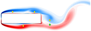
Figure 5. Instantaneous flow around the D-shaped cylinder with  ${A{\kern-4pt}R} =6$, represented with streamlines and vorticity colour maps. The periodic flow has period
  $T=5.6196$. (a–f) Six temporal instants at
  $t/T=0,0.08,0.16,0.24,0.32$ and
  $0.40$ are represented, respectively. Yellow diamonds indicate elliptical stagnation points, whereas green diamonds indicate the hyperbolic stagnation points.
At  $t/T=0$ (figure 5a), a vortex with positive (red) vorticity has just been shed in the wake from the bottom side of the cylinder. A small recirculating region of negative vorticity, instead, starts developing from the top TE corner, where vorticity accumulates before being shed in the wake. Then at
  $t/T=0.08$ the recirculating region widens, and when it reaches a critical size extending over the complete base of the cylinder (at
  $t/T=0.24$) the new TE vortex is shed in the wake. The TE vortex is shed concurrently with the appearance of a stagnation point in the hyperbolic region of the flow, a region with
  $\partial u / \partial x \partial v / \partial y - \partial u / \partial y \partial v / \partial x < 0$, just after the lower TE corner; this is a necessary condition for the occurrence of the vortex shedding (Boghosian & Cassel Reference Boghosian and Cassel2016).
3.3.2. The rectangular cylinder with ${A{\kern-4pt}R} =4$

The rectangular cylinder with  ${A{\kern-4pt}R} =4$ is representative of cases where the preferred TE shedding frequency is not permitted. Hence, the description of its flow features is valid for all the
  ${A{\kern-4pt}R}$ associated with the horizontal branches in the
  $St$–
$St$– ${A{\kern-4pt}R}$ diagram. Six snapshots are plotted in figure 6, corresponding to the six temporal instants
  $t/T=0.4,0.48,0.56,0.64,0.72$ and
  $0.8$. They have been chosen to properly highlight the shedding dynamics when the LE vortex reaches the TE corners (see figure 6a).

Figure 6. As for figure 5, but for a rectangular cylinder with  ${A{\kern-4pt}R} =4$, for which
  $T=7.0662$. (a–f) The six temporal instants are
  $t/T=0.4,0.48,0.56,0.64,0.72$ and
  $0.8$.
At  $t/T=0.4$, on the top cylinder side, a vortex with negative vorticity has just been shed in the wake, and a LE vortex has been advected until the TE. At
  $t/T=0.48$ this vortex passes the TE and effectively merges with the previous TE vortex. Concurrently, a recirculating region with positive vorticity starts developing from the bottom TE corner at
  $t/T=0.56$. As for the D-shaped cylinder, this recirculating region widens at
  $t/T=0.64$, until it extends almost over the whole cylinder base. Finally, once the LE vortex has completely passed the top TE corner at
  $t/T=0.72$, a hyperbolic stagnation point is generated just after the top TE corner, and the new TE vortex with positive vorticity is shed in the wake.
Hence, in this flow configuration, a new TE vortex of positive (negative) vorticity from the bottom (top) cylinder surface is shed concurrently with the passage of a LE vortex of negative (positive) vorticity over the top (bottom) TE corner. Therefore, the TE vortex shedding and the complete passage of a LE vortex over the same side TE corner take place at opposite phases. This type of vortex interaction indicates that, in this flow configuration, the (dimensional) shedding frequency  $f_{LE}$ is selected by the frequency of the LE vortices passing over the TE corner, i.e.
 \begin{equation} f_{LE} = \frac{n U_c}{L}, \end{equation}
as demonstrated by the fact that  $St$ does not depend on the cylinder length. Moreover, the TE vortex shedding is out of phase with respect to the case of the D-shaped cylinder.
3.3.3. The rectangular cylinder with ${A{\kern-4pt}R} =5$

The rectangular cylinder with  ${A{\kern-4pt}R} =5$ is representative of cases where the preferred TE shedding frequency is permitted. Hence, the description of its flow features is valid for all the
  ${A{\kern-4pt}R}$ associated with the oblique branches in the
  $St$–
$St$– ${A{\kern-4pt}R}$ diagram. Six snapshots are plotted in figure 7, corresponding to the same phases considered in § 3.3.1 when describing the D-shaped cylinder. As in the case with
  ${A{\kern-4pt}R} =4$, these phases have been chosen to properly highlight how a LE vortex interacts with the TE vortex shedding when it reaches the TE corner (see figure 7a).

Figure 7. As for figure 5 but for a rectangular cylinder with  ${A{\kern-4pt}R} =5$, for which
  $T=5.0668$. (a–f) The six temporal instants are
  $t/T=0,0.08,0.16,0.24,0.32$ and
  $0.40$.
At  $t/T=0$, a TE vortex with positive vorticity has just been shed from the bottom side of the cylinder, and a LE vortex with negative vorticity is reaching the top TE corner. After the LE vortex has reached the TE corner at
  $t/T=0.08$, a recirculating region of negative vorticity starts to develop from the top TE corner at
  $t/T=0.16$, similar to that observed for the D-shaped cylinder in the same phase. In the next phases, the LE vortex shrinks, whereas the recirculating region widens, revealing that the former is amalgamated into the latter. Then, when the TE recirculating region reaches its critical size at
  $t/T=0.32$, the newly generated TE vortex with negative vorticity is shed in the wake, simultaneously with the occurrence of a hyperbolic stagnation point just after the bottom TE corner (see figure 7e,e). Overall, the TE vortex shedding for
  ${A{\kern-4pt}R} =5$ is very similar to the case of the D-shaped cylinder. This observation further shows that, for this flow configuration, the overall shedding process is dominated by the TE vortex shedding. Indeed, in this case the LE vortices do not alter the TE vortex shedding: when they reach the TE corner, they simply merge with the newly developing recirculating region at the base of the cylinder before the new TE vortex is shed. Therefore, the LE vortex reaches the TE in phase with the formation of the new TE vortex. Note that this is similar to what Mills et al. (Reference Mills, Sheridan and Hourigan2003) observed for
  ${A{\kern-4pt}R} =6$ at slightly higher
  $Re=490$ via particle image velocimetry visualisations: indeed,
  ${A{\kern-4pt}R} =6$ is still in the oblique branch.
A closing observation is that the phase at which the LE vortex reaches the TE corner largely differs in the horizontal and oblique branches of the  $St$–
$St$– ${A{\kern-4pt}R}$ diagram. Indeed, for
  ${A{\kern-4pt}R} =4$ this occurs when a TE vortex starts being generated from the TE corner on the opposite side, whereas for
  ${A{\kern-4pt}R} =5$ this occurs when the TE vortex starts being generated from the TE corner on the same side.
3.4. On the origin of the LE vortex shedding
A global stability analysis is performed to investigate the origin of the vortex shedding from the shear layer separating at the LE corners. The symmetric steady flow around the rectangular cylinder with  ${A{\kern-4pt}R} =5$ at
  ${Re}=400$ is considered, but the conclusions drawn below are valid for the whole range of considered
  ${A{\kern-4pt}R}$. The steady base flow is obtained by solving the two-dimensional version of the Navier–Stokes equations using the Newton algorithm. Only the upper half of the domain used for the unsteady simulations is considered here, and symmetry boundary conditions are imposed on the
  $y=0$ axis, i.e.
 \begin{equation} \frac{\partial U}{\partial y}(x,0)=0, \quad V(x,0)=0. \end{equation}
At this Reynolds number, the steady base flow, shown in figure 8(a), presents a large recirculating region extending up to  $x=35.2$, delimited by a shear layer of negative vorticity which separates at the LE corner. The Reynolds number considered in this study is definitely above the onset of the primary instability, which consists of a Hopf bifurcation leading to the periodic vortex shedding from the TE, and has been determined by Chiarini, Quadrio & Auteri (Reference Chiarini, Quadrio and Auteri2021) to be
  $Re_{c,1} \approx 100$. However, this does not affect the present analysis, as we are only interested in whether the shear layer separating from the LE is absolutely unstable. Thus, we exclude from the global stability analysis the interaction between this shear layer and the vortex shedding from the TE, by considering the symmetric modes only. Additionally, the cross-talk between the pressure perturbation due to a vortex passing the TE corner and the shear layer on the opposite side is also excluded. Indeed, the goal is to ascertain whether or not the formation of the vortices on the rectangle side results from a one-side global instability.

Figure 8. Steady symmetric flow at  ${Re}=400$ for a rectangular cylinder with
  ${A{\kern-4pt}R} =5$ (a) and a sharp LE indefinite flat plate (b). Streamlines are shown superimposed on the vorticity contour map.
The outcome of the analysis is that no symmetric unstable modes are detected; at least at this Reynolds number, the shear layer separating from the LE is not absolutely unstable to one-side two-dimensional perturbations. The same result has been obtained by repeating the same global stability analysis, but considering the mean flow averaged over one shedding period.
An alternative approach to isolating the LE shear layer from the interaction with the TE vortices is considering a semi-infinite flat plate with a sharp LE, i.e. a rectangular cylinder of infinite length. Figure 8(b) shows the steady base flow at  ${Re}=400$. Again, a shear layer of negative vorticity separates from the top LE corner and a recirculation region develops over the lateral side of the plate, extending up to
  $x \approx 15.34$, (as in Thompson Reference Thompson2012). In this case the global stability analysis reveals that this base flow is absolutely unstable to neither symmetric nor antisymmetric modes. This agrees with the observation by Chaurasia & Thompson (Reference Chaurasia and Thompson2011) and Thompson (Reference Thompson2012) that in this flow configuration the onset of the shear layer flapping is due to a convective instability.
Therefore, this analysis shows that at the low- ${Re}$ regime considered in the present work, the onset of the vortex shedding from the shear layer separating at the LE corners is not due to an absolute instability. Most probably, instead, the shear layer is convectively unstable – as for the flat plate – and amplifies perturbations in a range of frequencies while they are convected downstream. The difference between rectangular cylinders and flat plates is that the perturbations amplified by the shear layer are generated by the pressure pulse originated by the interaction of the LE vortices with the TE (Hourigan et al. Reference Hourigan, Thompson and Tan2001), creating a self-sustained mechanism which is absent in the flow past a flat plate (Chaurasia & Thompson Reference Chaurasia and Thompson2011; Thompson Reference Thompson2012). We conclude that LE vortex shedding is not a one-sided global instability.
3.5. Temporal evolution of LE vortices
The discussion above implies qualitative and quantitative differences in the temporal evolution of the LE vortices, leading to a different evolution of both the elliptical and the hyperbolic stagnation points (compare figures 6 and 7), and changes to the successive two- and three-dimensional instabilities of the flow and to the transition to turbulence (Bayly, Orszag & Herbert Reference Bayly, Orszag and Herbert1988). Figure 9 shows the temporal evolution of the streamwise position of the elliptical stagnation points on the top side of the cylinder during one shedding period, for several values of  ${A{\kern-4pt}R}$. These points identify the centre of elliptically shaped streamlines and approximately indicate the centre of rotation of the LE vortices. The figure employs red squares to indicate LE vortices which are still attached to the shear layer, whereas white squares indicate shed vortices; blue diamonds denote the distance between two successive elliptic stagnation points when the associated LE vortices are both attached. In these phases of the shedding the two attached LE vortices are separated by a hyperbolic stagnation point, which disappears when the downstream one detaches after being shed (see figures 6 and 7).

Figure 9. Temporal evolution of the elliptical stagnation points on the top side of the cylinders during one shedding period. The  $x$ position of the stagnation points is drawn with a square, red when they are attached and white when they are shed. Blue diamonds denote the distance between two successive LE vortices when they are both attached.
The configuration with one vortex on the cylinder side, i.e.  $n=1$, is considered first. It is observed for
  ${A{\kern-4pt}R} =4$ and
  ${A{\kern-4pt}R} =4.75$, which are representative of the first horizontal branch. As expected, in both cases the LE vortices show the same temporal evolution. At
  $t/T=0$ an elliptical stagnation point is observed at
  $x \approx 1$, indicating that a new LE vortex is being generated; this is visible in the bottom side of figure 6(b). After remaining approximately at the same position for approximately
  $0.2T$, the stagnation point moves downstream, indicating that the LE vortex is widening. Approximately
  $1.2 T$ after it has been generated, the LE vortex is shed from the shear layer, and then it takes
  $0.35 T$ for it to reach the TE; see the bottom side of figure 6(c) and the top side of figure 6(b). Overall, in this flow configuration, it takes approximately
  $1.55 T$ for a LE vortex to reach the TE corner after being generated and thus to be shed in the wake. Since the LE vortex needs more than one period to grow up to the point where it can be shed from the shear layer, it closely interacts with the LE vortex generated in the next period. This interaction is highlighted in figures 6 and 9 by the presence of a hyperbolic stagnation point that separates the two recirculating regions before the older vortex is shed. For this flow configuration, the interaction between two successive vortices lasts
  $0.2 T$, as shown by the blue diamonds in figure 9.
The next flow configuration considered, with  $n=2$, shows a change in the LE vortex dynamics. We start with values of
  ${A{\kern-4pt}R}$ corresponding to points on the horizontal branch; see for example
  ${A{\kern-4pt}R} =7$ and
  ${A{\kern-4pt}R} =8$ in figure 9(g,h). Even in this case, the temporal evolution of the LE vortices does not change with
  ${A{\kern-4pt}R}$, as the flow is strongly locked and governed by the LE vortex passage frequency. In this flow configuration, the LE vortex is first generated at later phases compared with the above case, i.e.
  $t/T \approx 0.2$; the time required for the vortex to be shed and then to reach the TE corner increases to
  $1.5T$ and
  $0.9T$, respectively. Overall, the LE vortex needs
  $2.4T$ to reach and cross the TE corner. The duration of the interaction between two successively generated vortices increases up to approximately one half of the shedding period, as shown by the hyperbolic stagnation point which is detected for
  $0.2 \le t/T \le 0.7$.
The  $n=2$ configuration also includes aspect ratios where the flow belongs to the oblique branch. Typical values are
  ${A{\kern-4pt}R} =5$ and
  ${A{\kern-4pt}R} =5.5$. For these values of
  ${A{\kern-4pt}R}$, the LE vortices evolve differently, as the overall shedding process is governed by the TE vortex shedding, which also depends on
  ${A{\kern-4pt}R}$. For
  ${A{\kern-4pt}R} =4.8$ the new LE vortex is generated at
  $t/T \approx 0.3$ and needs approximately two shedding periods to enter the wake region; after
  $1.75T$ it is shed from the shear layer and then it takes
  $0.3 T$ to reach the TE. This increases the time window for the interaction of two consecutive LE vortices up to
  $0.75 T$. However, when increasing the aspect ratio further to
  ${A{\kern-4pt}R} =6$, the scenario changes and slowly approaches that already observed for
  ${A{\kern-4pt}R} =7$ and
  ${A{\kern-4pt}R} =8$. The phase at which the LE vortex is generated decreases, with a minimum for
  ${A{\kern-4pt}R} =5$ at
  $t/T \approx 0.16$, before increasing again. The overall time required by the vortices to reach the TE corner increases, and the hyperbolic stagnation point is present for only
  $0.5T$.
3.6. Discussion
This section describes the kinematic reason why the preferred TE frequency is admissible only for the rectangular cylinders with  ${A{\kern-4pt}R}$ on the oblique branches in the
  $St$–
$St$– ${A{\kern-4pt}R}$ diagram. Figure 10 compares, for the range
  $2 \le {A{\kern-4pt}R} \le 11$, the actual shedding period
  $T$, as measured by the numerical simulations, with the period
  $T_{LE}=L / (n U_c)$ corresponding to the LE vortex passage frequency in the lock-in regime and with the preferred TE shedding period
  $T_{TE}$. The mean convection velocity of the LE vortices is considered constant and equal to
  $U_c =0.55 U_{\infty }$, as reported by many authors (e.g. Nakamura et al. Reference Nakamura, Ohya and Tsuruta1991; Mills et al. Reference Mills, Sheridan and Hourigan2002; Tan et al. Reference Tan, Thompson and Hourigan2004).

Figure 10. Dependence on  ${A{\kern-4pt}R}$ of the shedding period in the configuration where the preferred frequency cannot be selected (
 $T_{LE}=L/n U_c$), the preferred TE period itself (
 $T_{TE}$) and the actual period (
 $T$).
$T$).
Figure 10 shows the simple evidence that, at each  ${A{\kern-4pt}R}$, the flow selects the configuration with the largest shedding period, i.e.
 \begin{equation} T = \max \left( T_{LE}, T_{TE} \right). \end{equation}
Hence, the preferred shedding period  $T_{TE}$ is admissible only when
  $T_{TE}>T_{LE}$. This is easily understood considering the case at
  ${A{\kern-4pt}R} =5$ described above. We have shown that, in this flow configuration, the LE vortices merge with the recirculating region accumulated in the cylinder base before the new TE vortex is shed in the wake. This is possible only when the time
  $T_{LE}$ needed by a new LE vortex to reach the TE corner is less than the undisturbed TE shedding period. In this case the passage of the LE vortex is in phase with the generation of the new TE vortex, as sketched in figure 11(a). Moreover, the difference
  $T_{TE} - T_{LE}$ may be thought of as an estimate of the time needed by the LE vortex to merge with the new TE vortex before shedding. Indeed, such time difference decreases as
  ${A{\kern-4pt}R}$ increases and becomes zero for the value of
  ${A{\kern-4pt}R}$ which separates the oblique and horizontal branches. In contrast, in the opposite case when
  $T_{TE}< T_{LE}$, the preferred shedding period
  $T_{TE}$ is not admissible as the merging between the LE and TE vortices cannot take place, since the time needed for a new LE vortex to reach the TE corner is longer than the TE shedding period. In this case, the two phenomena are out of phase, and the flow configuration described for
  ${A{\kern-4pt}R} =4$ is established; now the passage of the LE vortex over the TE corner is in phase with the generation of a new TE vortex from the opposite side of the cylinder. This is sketched in figure 11(b).

Figure 11. Sketch of the interaction between the LE and TE vortices. (a) Flow configuration with  $T_{TE}>T_{LE}$. (b) Flow configuration with
  $T_{TE}< T_{LE}$. Here
  $L^{-}$ denotes LE vortices with negative vorticity;
  $T^{-}$ denotes TE vortices with negative vorticity;
  $T^{+}$ denotes TE vortices with positive vorticity.
4. Hysteresis
The step change of the number  $n$ of vortices present over the side of the cylinder at a given time is responsible for the discontinuous dependence of the Strouhal number on
  ${A{\kern-4pt}R}$. In the range of aspect ratios considered in this work, the jump from
  $n=1$ to
  $n=2$ is observed for
  ${A{\kern-4pt}R} \ge 4.85$ or immediately below it, whereas the next jump to
  $n=3$ takes place for
  ${A{\kern-4pt}R} >8.25$. However, we report for the first time the existence of hysteresis: two stable flow configurations coexist within a subrange of
  ${A{\kern-4pt}R}$. As mentioned above, we believe this to be one of the possible explanations for the scatter of the available experimental and numerical data when
  ${A{\kern-4pt}R}$ is close to the jump values, and in particular for the multiple frequencies observed by several authors in certain
  ${A{\kern-4pt}R}$ ranges (Stokes & Welsh Reference Stokes and Welsh1986; Nakamura et al. Reference Nakamura, Ohya and Tsuruta1991; Ozono et al. Reference Ozono, Ohya, Nakamura and Nakayama1992; Hourigan et al. Reference Hourigan, Thompson and Tan2001).
We discuss here the first jump from  $n=1$ to
  $n=2$, but a similar picture applies also for the jump from
  $n=2$ to
  $n=3$. Hysteresis is studied via an additional set of simulations, where the aspect ratio is varied by small increments/decrements within the range of interest, i.e.
  $4.5 \le {A{\kern-4pt}R} \le 5.5$. Simulations are thus carried out twice and sequentially; the initial condition for each case is obtained by interpolating the velocity field from the previous simulation on the current grid. The results of the two sets of simulations in terms of
  $St$ are plotted in figure 12. They reveal that two stable configurations exist in the range
  $4.85 \le {A{\kern-4pt}R} \le 5.3125$: one corresponding to the
  $n=2$ oblique branch and one to the continuation of the
  $n=1$ horizontal branch. In contrast, for
  ${A{\kern-4pt}R} > 5.3125$ (
 ${A{\kern-4pt}R} < 4.85$), only the
  $n=2$ (
 $n=1$) configuration is stable: even with an initial condition corresponding to the
  $n=1$ (
 $n=2$) shedding mode, the simulations converge to the periodic flow configuration with frequency corresponding to the first oblique branch (first horizontal branch).

Figure 12. Evidence of hysteresis in the  $St$–
$St$– ${A{\kern-4pt}R}$ curve. The green and yellow diamonds denote the
  $n=1$ configuration before and after the Neimark–Sacker bifurcation (bif), respectively; red diamonds denote the
  $n=2$ configuration. Dashed lines delimit the range of
  ${A{\kern-4pt}R}$ for which both configurations are stable.
Let us consider now the continuation of the  $n=1$ horizontal branch. For
  $4.85 \le {A{\kern-4pt}R} \le 5$, the new simulations converge to a periodic solution with a single oscillation frequency corresponding to the
  $n=1$ shedding mode. For larger
  ${A{\kern-4pt}R}$, instead, the limit cycle loses stability through a Neimark–Sacker bifurcation (Kuznetsov Reference Kuznetsov2004); for such
  ${A{\kern-4pt}R}$, an invariant torus bifurcates from the limit cycle. This bifurcation is visualised in figure 12 by the yellow diamonds. For this range of
  ${A{\kern-4pt}R}$, the flow is no longer locked to a single frequency, but vortices are shed from the LE with a non-dimensional frequency
  $St_{LE}=1/T_{LE}$ (the central row of yellow diamonds) and from the TE with
  $St_{TE} = 1/T_{TE}$ (top row of yellow diamonds). However, different stable
  $(p,q)$ cycles on the bifurcated torus are observed, with
  $p$ and
  $q$ depending on
  ${A{\kern-4pt}R}$, corresponding to different Arnold tongues (Kuznetsov Reference Kuznetsov2004). This means that the two frequencies
  $St_{LE}$ and
  $St_{TE}$ lock, originating long-period cycles with period
  $T_{lp}=qT_{LE}=pT_{TE}$ (bottom row of yellow diamonds in figure 12); such
  $(p,q)$ cycles can be visualised as periodic orbits on the bifurcated torus that make
  $q$ revolutions along the parallel and
  $p$ revolutions along the meridian. For different
  ${A{\kern-4pt}R}$, the TE shedding frequency
  $St_{TE}$ slightly changes, and the flow locks to different long-period
  $(p,q)$ cycles; see figure 13 where the values of
  $p$ and
  $q$ for the different
  ${A{\kern-4pt}R}$ are shown. Three different Arnold tongues are detected, with
  $(p,q)=(9,17)$ for
  ${A{\kern-4pt}R} =5.0625$,
  $(p,q)=(8,15)$ for
  $5.125 \le {A{\kern-4pt}R} \le 5.1875$ and
  $(p,q)=(7,13)$ for
  $5.25 \le {A{\kern-4pt}R} \le 5.3125$. With increasing
  ${A{\kern-4pt}R}$, the
  $TE$ vortex shedding frequency decreases and the flow locks to periodic orbits with lower
  $p$ and
  $q$.
$q$.

Figure 13. Lock-in phenomenon in the Neimark–Sacker bifurcation on the  $n=1$ horizontal branch. Dependence of the Arnold tongue constants (a)
  $p$ and (b)
  $q$ on the aspect ratio
  ${A{\kern-4pt}R}$.
This is also visualised in figure 14 that plots the time history of the lift coefficient  $C_{\ell }$ for
  ${A{\kern-4pt}R} =4.85, 5.0626, 5.125, 5.25$, for the
  $n=1$ and
  $n=2$ configurations. For
  ${A{\kern-4pt}R} =4.85$ (figure 14a,b),
  $C_{\ell }$ is a periodic signal with a single oscillation frequency, and its period is
  $T_{LE}$ for the
  $n=1$ state and
  $T_{TE}$ for the
  $n=2$ state. As
  ${A{\kern-4pt}R}$ increases and the
  $n=1$ state bifurcates, the corresponding
  $C_{\ell }$ signal highlights the three different Arnold tongues (see figure 14c,e,g). The
  $C_{\ell }$ signal shows that the bifurcated state is dominated by the intermediate frequency between those visualised in figure 12. Note that, with increasing
  ${A{\kern-4pt}R}$, the number of local peaks of
  $C_{\ell }$ over one
  $T_{lp}$ period – associated with the number of LE vortices shed by the LE shear layer in the same period – decreases, consistently with the decrease of
  $p$ over the three detected Arnold tongues. A final comment regards the
  $n=2$ state, dominated by the TE vortex shedding. Besides the change in the flow periodicity already discussed, the increase of
  ${A{\kern-4pt}R}$ leads to a larger excursion of the
  $C_{\ell }$ (see figure 14b,d,f,h). Indeed, the peak of the lift coefficient
  $C_{\ell,p}$ increases with
  ${A{\kern-4pt}R}$ from
  $C_{\ell,p} \approx 0.4$ for
  ${A{\kern-4pt}R} =4.85$ to
  $C_{\ell,p} \approx 0.92$ for
  ${A{\kern-4pt}R} =6$.

Figure 14. Time history of the lift coefficients for  $4.85 \le {A{\kern-4pt}R} \le 5.25$ in the different states. Aspect ratio
  ${A{\kern-4pt}R} =$ (a,b) 4.85, (c,d) 5.0625, (e,f) 5.125 and (g,h) 5.25. (a,c,e,g) The
  $n=1$ (bifurcated) state and (b,d,f,h) the
  $n=2$ state. The time history of
  $C_{\ell }$ is plotted over one
  $T_{lp}$ period for the
  $n=1$ bifurcated state and over one
  $T_{TE}$ period for the other cases.
Figure 15 compares two instantaneous snapshots for  ${A{\kern-4pt}R} =5$, corresponding to the
  $n=1$ and
  $n=2$ configurations. The first configuration closely recalls that observed for
  ${A{\kern-4pt}R} =4$, with the TE vortex on the top side starting to develop as a LE vortex passes the bottom TE corner. In the configuration with
  $n=2$, the spacing between the wake vortices is almost halved; this confirms the nearly doubled shedding frequency of this solution.

Figure 15. Snapshots of the flow around the rectangular cylinder with  ${A{\kern-4pt}R} =5$, with the streamlines and vorticity colour maps, for (a)
  $n=1$ and (b)
  $n=2$.
Figure 16 shows the streamlines and the vorticity colour map for  ${A{\kern-4pt}R} =5.25$ in the
  $n=1$ bifurcated state. Six phases are considered within one of the seven LE shedding periods contained in the period
  $T_{lp}$. This figure should be compared with figure 6 to qualitatively appreciate the changes in the interaction of the LE and TE vortices for the
  $n=1$ configuration before and after the Neimark–Sacker bifurcation. Note that, for a complete characterisation of the bifurcated state, one should consider the overall
  $T_{lp}$ for the three different Arnold tongues detected, but this is omitted here for conciseness. In the selected LE shedding period, two TE vortices are shed by the top side of the cylinder, at
  $t/T_{LE}=0.27$ (figure 16b) and
  $t/T_{LE}=0.79$ (figure 16f). This agrees with the fact that, after the bifurcation, LE and TE shedding are not locked, and shows that the TE vortices are shed at a higher frequency that corresponds to the one for the
  $D$-shaped cylinder with the same
  ${A{\kern-4pt}R}$ (or for the same rectangular cylinder in the
  $n=2$ configuration); see the yellow diamonds at the top of figure 12. Moreover, during each LE shedding period, a pair of TE and LE vortices, shed on the opposite sides of the cylinder, interact just downstream of the TE to generate a pair of counter-rotating vortices before being eventually shed in the wake. Clearly, the dynamics of such counter-rotating vortices changes over successive LE shedding periods, as they interact at different phases of their shedding process.

Figure 16. As for figure 5, but for a rectangular cylinder with  ${A{\kern-4pt}R} =5.25$, in the bifurcated state obtained in the continuation of the
  $n=1$ horizontal branch. (a–f) The six temporal instants span one LE vortex shedding period; they are
  $t/T_{LE}=0.14,0.27,0.4,0.53,0.66$ and
  $0.79$.
Other studies of the flow past bluff bodies have shown that the blockage of the computational domain may affect the hysteresis. For example, Prasanth & Mittal (Reference Prasanth and Mittal2008) studying the vortex-induced vibrations of a circular cylinder at low Reynolds numbers observed hysteresis for a blockage ratio higher than 2.5 %, but detected an intermittent switching between the two detected modes for smaller blockage. We have investigated the effect of the blockage ratio on the present hysteresis phenomenon by performing further simulations for  ${A{\kern-4pt}R} =4.85$ and
  ${A{\kern-4pt}R} =5.125$, alternately decreasing the vertical size of the computational domain to
  $L_y = 20D$ and increasing it to
  $L_y=80D$. Therefore a total of three different values of the blockage ratio, i.e.
  $5\,\%$,
  $2.5\,\%$ and
  $1.25\,\%$, have been considered. These simulations have shown that hysteresis does not depend significantly on the blockage ratio, since the same scenario described above has been detected for both
  ${A{\kern-4pt}R} =4.85$ and
  ${A{\kern-4pt}R} =5.125$. How the hysteretic range of
  ${A{\kern-4pt}R}$ changes with blockage has been investigated too. All the simulations for
  $4.75 \le {A{\kern-4pt}R} \le 5.375$ have been repeated using the largest computational domain with
  $L_y=80$, continuing both the
  $n=1$ and the
  $n=2$ branches. Again, no differences have been observed with respect to the results obtained with the intermediate vertical size
  $L_y=40$.
The existence of multiple stable solutions, when  ${A{\kern-4pt}R}$ is close to the jump from one shedding mode to the next, may contribute to explain some apparently contradictory results in the literature. For example, at
  ${A{\kern-4pt}R} =5$, some works report the
  $n=1$ configuration (e.g. Hourigan et al. Reference Hourigan, Thompson and Tan2001), whereas others the
  $n=2$ configuration (e.g. Stokes & Welsh Reference Stokes and Welsh1986). When
  ${A{\kern-4pt}R} =8$ and
  $Re=1000$, Ozono et al. (Reference Ozono, Ohya, Nakamura and Nakayama1992) numerically observed that the flow pattern corresponds to the
  $n=2$ shedding mode at the earlier stage of the simulation, but approaches the
  $n=3$ shedding mode once the simulation was further advanced (see their figure 8 and figure 17 in Appendix B). Moreover, they found two frequencies in the time history of the lift coefficient, one associated with the horizontal branch with
  $n=2$ and one that has a frequency between that of the horizontal branches with
  $n=2$ and
  $n=3$. Indeed, this seems to indicate the existence of an
  $n=2$ solution where the preferred frequency is not permitted, accompanied by an
  $n=3$ solution where, instead, it is permitted.

Figure 17. Dependence of the Strouhal number  $St$ on the aspect ratio
  ${A{\kern-4pt}R}$. Comparison of the present results with previously published results. Present numerical data are at
  $Re=400$ (the
  $n=1$ bifurcated state is not reported for clarity). Experimental data from Nakamura et al. (Reference Nakamura, Ohya and Tsuruta1991) are at
  $Re=1000$. Numerical data from Ozono et al. (Reference Ozono, Ohya, Nakamura and Nakayama1992) are at
  $Re=1000$. Numerical data from Tan et al. (Reference Tan, Thompson and Hourigan1998) are at
  $Re=400$. Experimental data from Mills et al. (Reference Mills, Sheridan and Hourigan2003) are at
  $Re=490$.
Finally, the existence of these multiple solutions for a certain range of  ${A{\kern-4pt}R}$ may explain the results of Tan et al. (Reference Tan, Thompson and Hourigan2004). They numerically simulated the flow around rectangular cylinders for
  $6 \le {A{\kern-4pt}R} \le 16$ at
  $Re=400$ under transverse periodic forcing. They found that the flow locks at a different range of forcing frequencies depending on
  ${A{\kern-4pt}R}$, and that the maximum base suction occurs for a forcing frequency matching the ILEV instability frequency, i.e.
  $f_{LE}$. However, for some
  ${A{\kern-4pt}R}$, they observed two local maxima of the base suction for two different forcing frequencies, with the second one being between two consecutive horizontal branches of the
  $St$–
$St$– ${A{\kern-4pt}R}$ diagram (see figure 5 of their paper). We conjecture, again, that this happens because two stable configurations exist for those
  ${A{\kern-4pt}R}$ associated with two consecutive shedding modes.
5. Conclusions
The flow past elongated rectangular cylinders with aspect ratio  ${A{\kern-4pt}R} >3$ at moderate Reynolds numbers features vortex shedding from both the LE and TE corners (Nakamura et al. Reference Nakamura, Ohya and Tsuruta1991). Because of the interaction between the ILEV instability and the TE vortex shedding, shedding at LE and TE are interlocked, and the flow is periodic (Hourigan et al. Reference Hourigan, Thompson and Tan2001). Several works have provided evidence that this leads to a stepwise dependence of the chord-based Strouhal number
  $St$ on
  ${A{\kern-4pt}R}$; each step corresponds to a different shedding mode, associated with a different number of vortices simultaneously present over the cylinder side.
This work has described a refined interpretation of the flow dynamics, starting from the discovery that the  $St$–
$St$– ${A{\kern-4pt}R}$ diagram is stair-like and more complicated than previously known. Indeed, in some ranges of
  ${A{\kern-4pt}R}$, the curve has a qualitatively different shape, following an oblique branch instead of a horizontal one. Moreover, hysteresis has been observed for the first time near step changes of
  $St$.
$St$.
The study is based on an extensive numerical study, where the two-dimensional incompressible Navier–Stokes equations are solved for the flow past rectangular cylinders at  $Re=400$ with aspect ratio in the range
  $1 \le {A{\kern-4pt}R} \le 11$. Furthermore, a global stability analysis of the mean flow averaged over one shedding period has been performed. The eigenfrequencies of the leading eigenmodes have been found to predict very well the Strouhal number for all the
  ${A{\kern-4pt}R}$ considered. The visualisation of the spatial structure of the eigenmode is effective for clearly identifying the number of vortices simultaneously present over the cylinder side as
  ${A{\kern-4pt}R}$ varies. The analysis of the structural sensitivity confirms that the TE vortex shedding has a central role in the feedback loop which locks the flow at every
  ${A{\kern-4pt}R}$, and it also shows that the shear layers produced by the LE separation are active in the instability.
We have been able to establish that, depending on the value of  ${A{\kern-4pt}R}$, two distinct flow configurations may take place, one of them corresponding to horizontal branches in the
  $St$–
$St$– ${A{\kern-4pt}R}$ diagram, the other one to oblique branches. By way of a detailed study of the velocity and vorticity fields of the two configurations, it is found that the interaction between the LE and TE vortices changes on the two branches. The shedding frequency on the oblique branch matches that of the flow past D-shaped cylinders with the same
  ${A{\kern-4pt}R}$, revealing that in this case the flow frequency is selected by the TE vortex shedding. In this configuration, the LE vortex reaches the TE corner in phase with the development of a new TE vortex on the same side. In contrast, on the horizontal branch, the TE shedding frequency is not permitted by the relative phase of the LE vortices, which cross the TE corners out of phase with the shedding of the same-side TE vortex, but induce the shedding of the opposite-side TE vortex. Therefore, in this case, the flow frequency locks to the frequency of the LE vortices passing over the TE corners. Overall, at each
  ${A{\kern-4pt}R}$, the flow selects the configuration where the shedding period is largest, confirming that the flow frequency matches the natural TE shedding frequency only when this is permitted by the vortex phasing.
Finally, we have brought to light a hysteresis in the flow near the jump from one shedding mode to the next. For values of  ${A{\kern-4pt}R}$ close to the jump, the two flow configurations are both stable, and can indeed be separately observed. This may explain, at least partially, the scatter of several available literature data regarding the shedding frequency when
  ${A{\kern-4pt}R}$ is close to the jump, where sometimes more than one frequency is reported in the velocity spectra (e.g. Tan et al. Reference Tan, Thompson and Hourigan1998). We have also shown that, by increasing
  ${A{\kern-4pt}R}$ in the continuation of the
  $n=1$ horizontal branch, the periodic configuration loses stability through a Neimark–Sacker bifurcation, leading to new stable configurations for which the TE and LE vortex shedding are not locked to a single frequency. Different Arnold tongues are observed, meaning that the TE and LE shedding processes lock to different long-period configurations depending on
  ${A{\kern-4pt}R}$.
The (possibly simultaneous) existence of different configurations for the flow past rectangular cylinders is relevant for both practical and theoretical reasons. Obviously, different flow configurations and prevailing shedding modes lead to different time-varying distributions of the mechanical loads over the cylinder, which need to be properly accounted for in applications. But these results are also important to better understand the physics of this flow and, in particular, the process that leads to the flow breakdown. Indeed, the different interactions between the LE and TE vortices may lead to different successive two-dimensional and three-dimensional instabilities, and to a different path for the transition to turbulence. Work is underway to connect the present results to three-dimensional instability, transition and turbulence.
Declaration of interests
The authors report no conflict of interest.
Appendix A. Sensitivity of the results to domain size and resolution
In this appendix, the independence of the results from the domain size and grid resolution is addressed. Six further simulations have been performed for  ${A{\kern-4pt}R} =3,5$ and
  $7$ at
  $Re=400$, increasing the domain extent and grid resolution. In the
  $M_1$ mesh, the size of the domain has been increased in both the streamwise and cross-stream directions, while the same grid resolution has been adopted. The cross-stream extent of the domain has been increased from
  $L_y=40$ to
  $L_y=80$ for
  ${A{\kern-4pt}R} =3$ and
  $5$ and from
  $L_y=60$ to
  $L_y=80$ for
  $AR=7$, while the streamwise extent has been enlarged from
  $L_x=75$ and
  $L_x=100$ to
  $L_x=100$ and
  $L_x=125$, for
  ${A{\kern-4pt}R} =3,5$ and
  ${A{\kern-4pt}R} =7$, respectively. In the
  $M_2$ mesh, the size of the domain is the same as for
  $M_0$, but a finer grid resolution is used. The number of triangular elements is increased by approximately
  $60\,\%$, mainly increasing the resolution near the cylinder and in the wake region. The dimension of the domain used for the different grids is reported in table 2.
Table 2. Domain size for the grids employed in the grid-independence study.

As reported in table 3, the simulations with a larger computational domain predict a shedding period within  $0.74\,\%$,
  $0.49\,\%$ and
  $0.30\,\%$ of the values predicted with the smaller domain for
  ${A{\kern-4pt}R} =3,5$ and
  $7$, respectively. The mean and peak drag coefficients vary by
  $0.44\,\%$ and
  $0.97\,\%$ for
  ${A{\kern-4pt}R} =3$, by
  $0.69\,\%$ and
  $0.72\,\%$ for
  ${A{\kern-4pt}R} =5$ and by
  $0.27\,\%$ and
  $0.82\,\%$ for
  ${A{\kern-4pt}R} =7$. The peak lift coefficient, instead, varies by
  $0.68\,\%$,
  $1.8\,\%$ and
  $1.08\,\%$ for
  ${A{\kern-4pt}R} =3,5$ and
  $7$. The simulations with increased grid resolution, instead, predict a shedding period within
  $0.06\,\%$,
  $0.21\,\%$ and
  $0.13\,\%$ for the three values of
  ${A{\kern-4pt}R}$, while the mean and peak drag coefficients and the peak lift coefficient vary by
  $0.80\,\%$,
  $0.24\,\%$ and
  $0.82\,\%$ for
  ${A{\kern-4pt}R} =3$, by
  $0.28\,\%$,
  $0.34\,\%$ and
  $1.7\,\%$ for
  ${A{\kern-4pt}R} =5$ and by
  $0.39\,\%$,
  $0.42\,\%$ and
  $0.26\,\%$ for
  ${A{\kern-4pt}R} =7$.
Table 3. Variation of the drag and lift coefficients ( $C_d$ and
  $C_\ell$) and of the shedding period
  $T$ for
  ${A{\kern-4pt}R} =3,5$ and
  $7$ at
  $Re=400$ on three different meshes. Mesh
  $M_0$ indicates the mesh used for the computations in this work;
  $M_1$ indicates a mesh with larger cross-stream and streamwise dimensions with the same grid resolution; and
  $M_2$ indicates a mesh with the same domain size as
  $M_1$ but with finer grid resolution. Subscript ‘
 $m$’ indicates the mean value, while subscript ‘
 $p$’ indicates the peak value.

Appendix B. Quantitative comparison with previous data
Figure 17 shows a quantitative comparison of the present data with those taken from previously published works. Both numerical and experimental data are presented in the comparison, as well as different Reynolds numbers. For the present results, the  $n=1$ bifurcated state is not reported for clarity. All the considered works neatly detect the stepwise increase of
  $St$ with
  ${A{\kern-4pt}R}$, but for each state there is a scatter of the data roughly of the order of
  ${\pm } 10\,\%$. The scatter is probably not only caused by the different Reynolds numbers but also due to the difference in the set-up of both experiments and numerical simulations. In any case, figure 17 shows that the results of the present work are well within the range of the available data.


