


1 Introduction
The problem of turbulent axisymmetric wakes under pressure gradient is interesting, and its study is useful; first, because it can be regarded as a classical fundamental fluid mechanics problem, and, second, because such a phenomenon can have engineering implications. One example that is worthy of attention is the design of wind farms sited on topography. The axisymmetric wind turbine wakes are subjected to non-zero pressure gradients, which are caused by variations in the underlying terrain elevation. This changes the wake recovery characteristics of the wind turbines with respect to the flat terrain case, and, in turn, can affect the design of the optimum layout of the wind farm.
In spite of its importance, few studies have been carried out on this subject. In their analytical study on wakes in complex flows, Hunt & Eames (Reference Hunt and Eames2002), among other things, derived the solution for the mean velocity for a laminar axisymmetric wake under a specific strain caused by an external flow. Magnaudet, Rivero & Fabre (Reference Magnaudet, Rivero and Fabre1995) and Bagchi & Balachandar (Reference Bagchi and Balachandar2002) performed numerical simulations of flow past a sphere (rigid and bubble-like) that was subjected to strain (planar and axisymmetric). The focus of their studies was more on the direct impact of the flow on the sphere (e.g. forces, separation, etc.) rather than the evolution of the wake itself. In contrast to turbulent axisymmetric wakes, some interesting research has already been performed for the planar case using numerical (Rogers Reference Rogers2002) and experimental (Liu, Thomas & Nelson Reference Liu, Thomas and Nelson2002; Thomas & Liu Reference Thomas and Liu2004) approaches, supported also by concurrent analytical (Shamsoddin & Porté-Agel Reference Shamsoddin and Porté-Agel2017b ) developments. Based on these studies, it is known that favourable pressure gradients (accelerating base flows) lead to a faster recovery of the wake.
As mentioned in the conclusion of Shamsoddin & Porté-Agel (Reference Shamsoddin and Porté-Agel2017b ), turbulent axisymmetric wakes ought to be studied under the influence of imposed pressure gradients, especially because of the arising of such scenarios in the case of wind turbine wakes over topography. In the present paper, we aim to accomplish this objective by proposing an analytical framework to analyse such wakes and eventually by developing a model to predict how an arbitrary imposed non-zero pressure gradient alters the evolution of a turbulent axisymmetric wake under zero pressure gradient. In addition, we provide large-eddy simulation (LES) results related to such wakes, against which we can test our model. To the best knowledge of the authors, no study (experimental, numerical or analytical) on this topic (turbulent axisymmetric wakes under different imposed pressure gradients) is available in the literature. Therefore, this paper can provide useful insight (by presenting both a theoretical framework and an LES dataset) related to this subject.
This article is ordered in the following manner. In § 2, the problem is defined and the model is derived with all of its variants. In § 3, the numerical experiments, which are performed for the purpose of validation of the model, are described and their results are compared with the predictions of the model. Finally, § 4 concludes the paper.
2 Analytical model for axisymmetric wakes under pressure gradient
2.1 Problem formulation
The mean velocity deficit profiles of turbulent axisymmetric wakes are known to be self-similar and to have a Gaussian shape function (Pope Reference Pope2000),
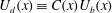
 $$\begin{eqnarray}\displaystyle & \displaystyle \frac{U_{b}(x)-\overline{u}(x,r)}{U_{b}(x)}\equiv C(x)\text{e}^{-(r^{2}/2\unicode[STIX]{x1D6FF}^{2})}, & \displaystyle\end{eqnarray}$$
where
 $x$
is the streamwise direction,
$x$
is the streamwise direction,
 $r$
is the radial direction from the wake centre,
$r$
is the radial direction from the wake centre,
 $\overline{u}(x,r)$
is the velocity (hereafter, by velocity, we imply the mean streamwise velocity, unless otherwise stated) of the wake flow,
$\overline{u}(x,r)$
is the velocity (hereafter, by velocity, we imply the mean streamwise velocity, unless otherwise stated) of the wake flow,
 $U_{b}(x)$
is the velocity of the base flow,
$U_{b}(x)$
is the velocity of the base flow,
 $C(x)$
is a function determining the maximum velocity deficit at each
$C(x)$
is a function determining the maximum velocity deficit at each
 $x$
-position and
$x$
-position and
 $\unicode[STIX]{x1D6FF}(x)$
is the wake width.
$\unicode[STIX]{x1D6FF}(x)$
is the wake width.
Here, we assume that the axisymmetric wake retains its Gaussian shape under non-zero pressure gradients. This assumption will be verified later in this paper (§ 3). It is noteworthy to mention that it has already been shown that for a turbulent planar wake, this assumption is valid (Liu et al. Reference Liu, Thomas and Nelson2002; Rogers Reference Rogers2002; Shamsoddin & Porté-Agel Reference Shamsoddin and Porté-Agel2017b ).
The imposed pressure gradient is manifested in the above formulation in the function
 $U_{b}(x)$
. For an accelerating base flow (
$U_{b}(x)$
. For an accelerating base flow (
 $\text{d}U_{b}/\text{d}x>0$
), we have the so-called favourable pressure gradient (FPG), and for a decelerating base flow (
$\text{d}U_{b}/\text{d}x>0$
), we have the so-called favourable pressure gradient (FPG), and for a decelerating base flow (
 $\text{d}U_{b}/\text{d}x<0$
), we have the so-called adverse pressure gradient (APG). Obviously, for the zero-pressure-gradient (ZPG) case,
$\text{d}U_{b}/\text{d}x<0$
), we have the so-called adverse pressure gradient (APG). Obviously, for the zero-pressure-gradient (ZPG) case,
 $U_{b}(x)=U_{b0}=\text{const}$
.
$U_{b}(x)=U_{b0}=\text{const}$
.
Our objective in this section is to solve the following problem: for a given ZPG wake (for which we know the wake width evolution), how is the mean velocity field of the wake (i.e.
 $C(x)$
and
$C(x)$
and
 $\unicode[STIX]{x1D6FF}(x)$
) changed after imposing an arbitrary pressure gradient?
$\unicode[STIX]{x1D6FF}(x)$
) changed after imposing an arbitrary pressure gradient?
2.2 Model derivation
The mean conservation of momentum equation in the
 $x$
-direction for a turbulent axisymmetric wake can be written as
$x$
-direction for a turbulent axisymmetric wake can be written as
 $$\begin{eqnarray}\displaystyle & \displaystyle \frac{\unicode[STIX]{x2202}\overline{u}(U_{b}-\overline{u})}{\unicode[STIX]{x2202}x}+\frac{\unicode[STIX]{x2202}\bar{v}(U_{b}-\overline{u})}{\unicode[STIX]{x2202}y}+\frac{\unicode[STIX]{x2202}\bar{w}(U_{b}-\overline{u})}{\unicode[STIX]{x2202}z}=-\frac{\text{d}U_{b}}{\text{d}x}(U_{b}-\overline{u})+\frac{\unicode[STIX]{x2202}\overline{u^{\prime }v^{\prime }}}{\unicode[STIX]{x2202}y}+\frac{\unicode[STIX]{x2202}\overline{u^{\prime }w^{\prime }}}{\unicode[STIX]{x2202}z}, & \displaystyle\end{eqnarray}$$
where
 $u$
,
$u$
,
 $v$
and
$v$
and
 $w$
are the streamwise (
$w$
are the streamwise (
 $x$
), lateral (
$x$
), lateral (
 $y$
) and vertical (
$y$
) and vertical (
 $z$
) components of the velocity, the overbar indicates a mean quantity and the prime shows the fluctuation quantities (e.g.
$z$
) components of the velocity, the overbar indicates a mean quantity and the prime shows the fluctuation quantities (e.g.
 $u^{\prime }=u-\overline{u}$
). In deriving this equation, the continuity equation is used, the viscous and
$u^{\prime }=u-\overline{u}$
). In deriving this equation, the continuity equation is used, the viscous and
 $\unicode[STIX]{x2202}\overline{{u^{\prime }}^{2}}/\unicode[STIX]{x2202}x$
terms are neglected, and the mean pressure gradient term,
$\unicode[STIX]{x2202}\overline{{u^{\prime }}^{2}}/\unicode[STIX]{x2202}x$
terms are neglected, and the mean pressure gradient term,
 $-(1/\unicode[STIX]{x1D70C})\unicode[STIX]{x2202}\overline{p}/\unicode[STIX]{x2202}x$
, is replaced by
$-(1/\unicode[STIX]{x1D70C})\unicode[STIX]{x2202}\overline{p}/\unicode[STIX]{x2202}x$
, is replaced by
 $U_{b}(\text{d}U_{b}/\text{d}x)$
. For intermediate steps, through which this equation is obtained, the interested reader is referred to Shamsoddin & Porté-Agel (Reference Shamsoddin and Porté-Agel2017b
).
$U_{b}(\text{d}U_{b}/\text{d}x)$
. For intermediate steps, through which this equation is obtained, the interested reader is referred to Shamsoddin & Porté-Agel (Reference Shamsoddin and Porté-Agel2017b
).
After integrating in the
 $x$
-normal plane, we obtain the integral form of the
$x$
-normal plane, we obtain the integral form of the
 $x$
-momentum equation,
$x$
-momentum equation,
 $$\begin{eqnarray}\displaystyle & \displaystyle \frac{\text{d}}{\text{d}x}\int _{0}^{\infty }\overline{u}(U_{b}-\overline{u})(2\unicode[STIX]{x03C0}r\,\text{d}r)+\int _{0}^{\infty }\frac{\text{d}U_{b}}{\text{d}x}(U_{b}-\overline{u})(2\unicode[STIX]{x03C0}r\,\text{d}r)=0. & \displaystyle\end{eqnarray}$$
It should be noted that, as
 $(U_{b}-\overline{u})$
,
$(U_{b}-\overline{u})$
,
 $\overline{u^{\prime }v^{\prime }}$
and
$\overline{u^{\prime }v^{\prime }}$
and
 $\overline{u^{\prime }w^{\prime }}$
all vanish far from the wake centre (in a given
$\overline{u^{\prime }w^{\prime }}$
all vanish far from the wake centre (in a given
 $x$
-normal plane), the integrals of the last two terms on both sides of (2.2) are zero. Here, we assume that the strain that causes the pressure gradient is also axisymmetric, and therefore the wake retains its axisymmetry after imposing the pressure gradient (for the case of a planar strain, see § 2.4). Thus, we can directly substitute (2.1) into (2.3) and use
$x$
-normal plane), the integrals of the last two terms on both sides of (2.2) are zero. Here, we assume that the strain that causes the pressure gradient is also axisymmetric, and therefore the wake retains its axisymmetry after imposing the pressure gradient (for the case of a planar strain, see § 2.4). Thus, we can directly substitute (2.1) into (2.3) and use
 $\int _{0}^{\infty }\exp [-r^{2}/(2\unicode[STIX]{x1D6FF}^{2})](2\unicode[STIX]{x03C0}r\,\text{d}r)=2\unicode[STIX]{x03C0}\unicode[STIX]{x1D6FF}^{2}$
to obtain
$\int _{0}^{\infty }\exp [-r^{2}/(2\unicode[STIX]{x1D6FF}^{2})](2\unicode[STIX]{x03C0}r\,\text{d}r)=2\unicode[STIX]{x03C0}\unicode[STIX]{x1D6FF}^{2}$
to obtain
 $$\begin{eqnarray}\displaystyle & \displaystyle \frac{\text{d}}{\text{d}x}\left[2\unicode[STIX]{x03C0}U_{b}^{2}(x)\unicode[STIX]{x1D6FF}^{2}(x)\left(C(x)-\frac{C^{2}(x)}{2}\right)\right]+\unicode[STIX]{x03C0}\frac{\text{d}U_{b}^{2}}{\text{d}x}\unicode[STIX]{x1D6FF}^{2}(x)C(x)=0. & \displaystyle\end{eqnarray}$$
As can be seen, we are left with a nonlinear ordinary differential equation (ODE). We first show the solution of the equation for the ZPG case, because it proves to be helpful later. In fact, in the ZPG case, (2.4) reduces to an algebraic equation (the second term vanishes), whose solution has already been obtained by Bastankhah & Porté-Agel (Reference Bastankhah and Porté-Agel2014),
 $$\begin{eqnarray}\displaystyle & \displaystyle C_{0}(x)=1-\sqrt{1-\frac{C_{D}}{8\left({\displaystyle \frac{\unicode[STIX]{x1D6FF}_{0}(x)}{D}}\right)^{2}}}\quad (x\geqslant x_{i}), & \displaystyle\end{eqnarray}$$
where the subscript
 $0$
indicates a quantity in the ZPG case,
$0$
indicates a quantity in the ZPG case,
 $D$
is the diameter of the wake-generating object and
$D$
is the diameter of the wake-generating object and
 $C_{D}$
is the drag coefficient of the object (or in the case of a power-generating device, the thrust coefficient). The condition
$C_{D}$
is the drag coefficient of the object (or in the case of a power-generating device, the thrust coefficient). The condition
 $(x\geqslant x_{i})$
is only to make sure that the expression under the square root always remains non-negative.
$(x\geqslant x_{i})$
is only to make sure that the expression under the square root always remains non-negative.
Now, we focus on the ODE of (2.4). In this ODE, we have one equation and two unknowns (
 $C$
and
$C$
and
 $\unicode[STIX]{x1D6FF}$
). Therefore, we need another equation to close the problem. For this purpose, following Shamsoddin & Porté-Agel (Reference Shamsoddin and Porté-Agel2017b
), we use the invariance of the ratio
$\unicode[STIX]{x1D6FF}$
). Therefore, we need another equation to close the problem. For this purpose, following Shamsoddin & Porté-Agel (Reference Shamsoddin and Porté-Agel2017b
), we use the invariance of the ratio
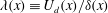 $\unicode[STIX]{x1D706}(x)\equiv U_{d}(x)/\unicode[STIX]{x1D6FF}(x)$
under pressure gradient changes, where
$\unicode[STIX]{x1D706}(x)\equiv U_{d}(x)/\unicode[STIX]{x1D6FF}(x)$
under pressure gradient changes, where
 $U_{d}(x)\equiv C(x)U_{b}(x)$
is the maximum velocity deficit at a given streamwise position. This invariance has been shown experimentally (Liu et al.
Reference Liu, Thomas and Nelson2002; Thomas & Liu Reference Thomas and Liu2004) and has been used to develop a model for the case of planar wakes by Shamsoddin & Porté-Agel (Reference Shamsoddin and Porté-Agel2017b
). For the case of axisymmetric wakes, we will reaffirm the validity of this assumption based on LES data in § 3. Hence, because
$U_{d}(x)\equiv C(x)U_{b}(x)$
is the maximum velocity deficit at a given streamwise position. This invariance has been shown experimentally (Liu et al.
Reference Liu, Thomas and Nelson2002; Thomas & Liu Reference Thomas and Liu2004) and has been used to develop a model for the case of planar wakes by Shamsoddin & Porté-Agel (Reference Shamsoddin and Porté-Agel2017b
). For the case of axisymmetric wakes, we will reaffirm the validity of this assumption based on LES data in § 3. Hence, because
 $\unicode[STIX]{x1D706}$
is insensitive to pressure gradient and thus
$\unicode[STIX]{x1D706}$
is insensitive to pressure gradient and thus
 $U_{b}$
, we have
$U_{b}$
, we have
 $$\begin{eqnarray}\displaystyle & \displaystyle \unicode[STIX]{x1D706}(x)=\unicode[STIX]{x1D706}_{0}(x)=\frac{U_{b0}C_{0}(x)}{\unicode[STIX]{x1D6FF}_{0}(x)}. & \displaystyle\end{eqnarray}$$
Consequently,
 $\unicode[STIX]{x1D6FF}$
can be expressed as
$\unicode[STIX]{x1D6FF}$
can be expressed as
 $$\begin{eqnarray}\displaystyle & \displaystyle \unicode[STIX]{x1D6FF}(x)=\frac{U_{b}(x)}{\unicode[STIX]{x1D706}_{0}(x)}C(x). & \displaystyle\end{eqnarray}$$
Now, substituting (2.7) into (2.4), the final ODE for
 $C(x)$
is obtained,
$C(x)$
is obtained,
 $$\begin{eqnarray}\displaystyle & \displaystyle \frac{\text{d}C(x)}{\text{d}x}={\displaystyle \frac{-1}{\left({\displaystyle \frac{U_{b}^{4}}{\unicode[STIX]{x1D706}_{0}^{2}}}\right)\left(3C^{2}-2C^{3}\right)}}\left[\frac{1}{4}\frac{\text{d}U_{b}^{4}}{\text{d}x}\frac{C^{3}}{\unicode[STIX]{x1D706}_{0}^{2}}+\left(C^{3}-\frac{C^{4}}{2}\right)\frac{\text{d}}{\text{d}x}\left({\displaystyle \frac{U_{b}^{4}}{\unicode[STIX]{x1D706}_{0}^{2}}}\right)\right], & \displaystyle\end{eqnarray}$$
with the boundary condition
 $$\begin{eqnarray}\displaystyle & \displaystyle C(x_{i})=C_{0}(x_{i}). & \displaystyle\end{eqnarray}$$
Equation (2.8) is a nonlinear ODE in the explicit form of
 $\text{d}C(x)/\text{d}x=f(U_{b},\unicode[STIX]{x1D706}_{0},C(x))$
. This ODE can be solved easily and rapidly with common commercial ODE solvers. Thus, with (2.8) and (2.9), our objective, which was the solution of the problem defined in § 2.1, is accomplished.
$\text{d}C(x)/\text{d}x=f(U_{b},\unicode[STIX]{x1D706}_{0},C(x))$
. This ODE can be solved easily and rapidly with common commercial ODE solvers. Thus, with (2.8) and (2.9), our objective, which was the solution of the problem defined in § 2.1, is accomplished.
2.3 Asymptotic solution of the problem
Since
 $\overline{u}\rightarrow U_{b}$
far downstream of the wake-generating object, we have
$\overline{u}\rightarrow U_{b}$
far downstream of the wake-generating object, we have
 $C^{2}(x)\ll C(x)$
for sufficiently large
$C^{2}(x)\ll C(x)$
for sufficiently large
 $x$
(at least for the FPG and ZPG cases) (Shamsoddin & Porté-Agel Reference Shamsoddin and Porté-Agel2017b
). Therefore, neglect of the term involving
$x$
(at least for the FPG and ZPG cases) (Shamsoddin & Porté-Agel Reference Shamsoddin and Porté-Agel2017b
). Therefore, neglect of the term involving
 $C^{2}(x)$
in (2.4) leads to the following linear ODE:
$C^{2}(x)$
in (2.4) leads to the following linear ODE:
 $$\begin{eqnarray}\displaystyle & \displaystyle \frac{\text{d}}{\text{d}x}\left[2\unicode[STIX]{x03C0}U_{b}^{2}(x)\unicode[STIX]{x1D6FF}^{2}(x)\widetilde{C}(x)\right]+\unicode[STIX]{x03C0}\frac{\text{d}U_{b}^{2}}{\text{d}x}\unicode[STIX]{x1D6FF}^{2}(x)\widetilde{C}(x)=0, & \displaystyle\end{eqnarray}$$
where
 $\widetilde{C}$
is the asymptotic solution of
$\widetilde{C}$
is the asymptotic solution of
 $C$
. The above equation is exactly equivalent to the following:
$C$
. The above equation is exactly equivalent to the following:
 $$\begin{eqnarray}\displaystyle & \displaystyle 2\unicode[STIX]{x03C0}\frac{1}{U_{b}}\frac{\text{d}}{\text{d}x}\left[\unicode[STIX]{x1D6FF}^{2}(x)\widetilde{C}(x)U_{b}^{3}\right]=0. & \displaystyle\end{eqnarray}$$
Using the readily obtainable asymptotic ZPG solution for
 $\widetilde{C}_{0}$
from (2.4) (i.e.
$\widetilde{C}_{0}$
from (2.4) (i.e.
 $\widetilde{C}_{0}=D^{2}C_{D}/(16\unicode[STIX]{x1D6FF}_{0}^{2})$
) to find the correct constant of integration, the solution to (2.11) can be found as
$\widetilde{C}_{0}=D^{2}C_{D}/(16\unicode[STIX]{x1D6FF}_{0}^{2})$
) to find the correct constant of integration, the solution to (2.11) can be found as
 $$\begin{eqnarray}\displaystyle & \displaystyle \widetilde{C}(x)=\frac{1}{16}\frac{C_{D}}{\left({\displaystyle \frac{\unicode[STIX]{x1D6FF}(x)}{D}}\right)^{2}}\left(\frac{U_{b0}}{U_{b}(x)}\right)^{3}, & \displaystyle\end{eqnarray}$$
which by employing (2.6)–(2.7) can be further simplified to
 $$\begin{eqnarray}\displaystyle & \displaystyle \widetilde{C}(x)=\widetilde{C}_{0}\left(\frac{U_{b0}}{U_{b}(x)}\right)^{5/3}. & \displaystyle\end{eqnarray}$$
It is noteworthy that for the planar case the exponent of
 $(U_{b0}/U_{b})$
was found to be 2 (Shamsoddin & Porté-Agel Reference Shamsoddin and Porté-Agel2017b
), whereas for the axisymmetric case this exponent is
$(U_{b0}/U_{b})$
was found to be 2 (Shamsoddin & Porté-Agel Reference Shamsoddin and Porté-Agel2017b
), whereas for the axisymmetric case this exponent is
 $5/3$
. Furthermore,
$5/3$
. Furthermore,
 $\widetilde{C}_{0}(x)$
can be shown to be the second-order Taylor expansion of the full solution of
$\widetilde{C}_{0}(x)$
can be shown to be the second-order Taylor expansion of the full solution of
 $C_{0}(x)$
, i.e. (2.5), in terms of
$C_{0}(x)$
, i.e. (2.5), in terms of
 $\unicode[STIX]{x1D6FF}_{0}^{-1}$
.
$\unicode[STIX]{x1D6FF}_{0}^{-1}$
.
2.4 Axisymmetric wakes and planar strain
In the above derivations, we had assumed an axisymmetric strain and, consequently, that the wake retains its axisymmetry (e.g. when a wake passes through a circular nozzle/diffuser). This assumption provides a perfect analogy to the case of a planar wake under a planar strain (e.g. Liu et al. Reference Liu, Thomas and Nelson2002; Thomas & Liu Reference Thomas and Liu2004; Shamsoddin & Porté-Agel Reference Shamsoddin and Porté-Agel2017b ). In this subsection, we are interested in studying the case of an axisymmetric wake that undergoes an imposed pressure gradient that is a result of a planar strain (e.g. when passing through a planar nozzle/diffuser). This case is interesting because of its practical use, in particular, for the case of wind turbine wakes flowing over topography: in this case the topography generates a planar strain on the axisymmetric wake of a wind turbine rotor.
Without losing generality, we consider the planar strain to be in the
 $z$
-direction. In this case (unlike the axisymmetric strain case), the wake widths in the
$z$
-direction. In this case (unlike the axisymmetric strain case), the wake widths in the
 $y$
- and
$y$
- and
 $z$
-directions are not necessarily equal. Therefore, following Bastankhah & Porté-Agel (Reference Bastankhah and Porté-Agel2016), we assume that the velocity deficit profile of the wake has the following general shape:
$z$
-directions are not necessarily equal. Therefore, following Bastankhah & Porté-Agel (Reference Bastankhah and Porté-Agel2016), we assume that the velocity deficit profile of the wake has the following general shape:
 $$\begin{eqnarray}\displaystyle & \displaystyle \frac{U_{b}(x)-\overline{u}(x,y,z)}{U_{b}(x)}\equiv C(x)\exp \left[-\!\left({\displaystyle \frac{y^{2}}{2\unicode[STIX]{x1D6FF}_{y}^{2}}}+{\displaystyle \frac{z^{2}}{2\unicode[STIX]{x1D6FF}_{z}^{2}}}\right)\right], & \displaystyle\end{eqnarray}$$
where
 $\unicode[STIX]{x1D6FF}_{y}$
and
$\unicode[STIX]{x1D6FF}_{y}$
and
 $\unicode[STIX]{x1D6FF}_{z}$
are the wake widths in the
$\unicode[STIX]{x1D6FF}_{z}$
are the wake widths in the
 $y$
- and
$y$
- and
 $z$
-directions. In the case of
$z$
-directions. In the case of
 $\unicode[STIX]{x1D6FF}_{y}=\unicode[STIX]{x1D6FF}_{z}$
, the above equation reduces to (2.1) (as in Vermeulen, Builtjes & Dekker Reference Vermeulen, Builtjes, Dekker and Lammerts van Bueren1979; Jensen Reference Jensen1983; Bastankhah & Porté-Agel Reference Bastankhah and Porté-Agel2014). We have
$\unicode[STIX]{x1D6FF}_{y}=\unicode[STIX]{x1D6FF}_{z}$
, the above equation reduces to (2.1) (as in Vermeulen, Builtjes & Dekker Reference Vermeulen, Builtjes, Dekker and Lammerts van Bueren1979; Jensen Reference Jensen1983; Bastankhah & Porté-Agel Reference Bastankhah and Porté-Agel2014). We have
 $\int _{-\infty }^{\infty }\int _{-\infty }^{\infty }\exp [-(y^{2}/(2\unicode[STIX]{x1D6FF}_{y}^{2})+z^{2}/(2\unicode[STIX]{x1D6FF}_{z}^{2}))]\,\text{d}y\,\text{d}z=2\unicode[STIX]{x03C0}\unicode[STIX]{x1D6FF}_{y}\unicode[STIX]{x1D6FF}_{z}$
, and this paves the way to define an equivalent wake width
$\int _{-\infty }^{\infty }\int _{-\infty }^{\infty }\exp [-(y^{2}/(2\unicode[STIX]{x1D6FF}_{y}^{2})+z^{2}/(2\unicode[STIX]{x1D6FF}_{z}^{2}))]\,\text{d}y\,\text{d}z=2\unicode[STIX]{x03C0}\unicode[STIX]{x1D6FF}_{y}\unicode[STIX]{x1D6FF}_{z}$
, and this paves the way to define an equivalent wake width
 $\unicode[STIX]{x1D6FF}_{eq}$
as the geometric mean of
$\unicode[STIX]{x1D6FF}_{eq}$
as the geometric mean of
 $\unicode[STIX]{x1D6FF}_{y}$
and
$\unicode[STIX]{x1D6FF}_{y}$
and
 $\unicode[STIX]{x1D6FF}_{z}$
,
$\unicode[STIX]{x1D6FF}_{z}$
,
 $$\begin{eqnarray}\displaystyle & \displaystyle \unicode[STIX]{x1D6FF}_{eq}=\sqrt{\unicode[STIX]{x1D6FF}_{y}\unicode[STIX]{x1D6FF}_{z}}. & \displaystyle\end{eqnarray}$$
Now, if we substitute (2.14) into (2.3), and follow the same procedure as in §§ 2.2 and 2.3, we obtain exactly the same equations, with the only difference being that
 $\unicode[STIX]{x1D6FF}_{eq}$
replaces
$\unicode[STIX]{x1D6FF}_{eq}$
replaces
 $\unicode[STIX]{x1D6FF}$
in all of those equations.
$\unicode[STIX]{x1D6FF}$
in all of those equations.
In fact, in the case of planar strain, we solve our problem for
 $C(x)$
and
$C(x)$
and
 $\unicode[STIX]{x1D6FF}_{eq}(x)$
. In order to further obtain
$\unicode[STIX]{x1D6FF}_{eq}(x)$
. In order to further obtain
 $\unicode[STIX]{x1D6FF}_{y}$
and
$\unicode[STIX]{x1D6FF}_{y}$
and
 $\unicode[STIX]{x1D6FF}_{z}$
individually, we require more information about the geometry and history of the flow and strain, which is beyond the scope of the framework of the current model. However, being able to predict
$\unicode[STIX]{x1D6FF}_{z}$
individually, we require more information about the geometry and history of the flow and strain, which is beyond the scope of the framework of the current model. However, being able to predict
 $C(x)$
and
$C(x)$
and
 $\unicode[STIX]{x1D6FF}_{eq}$
still enables us to obtain a great deal of information about the flow which can be useful in many practical applications.
$\unicode[STIX]{x1D6FF}_{eq}$
still enables us to obtain a great deal of information about the flow which can be useful in many practical applications.
3 Validation of the model
3.1 The numerical experiment
To validate the model, we compare its results with results from the LES of axisymmetric wakes in three specific FPG, ZPG and APG cases. The numerical experiments are performed in an ideal spanwise-periodic channel with rectangular cross-section. To create the desired non-zero pressure gradient, the walls of the channel are curved so that its cross-sectional area varies in the streamwise direction. The wake itself is generated with an actuator disk of diameter
 $D$
and drag (or thrust) coefficient
$D$
and drag (or thrust) coefficient
 $C_{D}=0.8$
. As can be seen in figure 1, three different geometries of the channel wall are used respectively for the FPG, ZPG and APG cases: (i) convex walls, which create a contraction and consequently flow acceleration (
$C_{D}=0.8$
. As can be seen in figure 1, three different geometries of the channel wall are used respectively for the FPG, ZPG and APG cases: (i) convex walls, which create a contraction and consequently flow acceleration (
 $\text{d}U_{b}/\text{d}x>0$
) up to the channel throat, (ii) straight walls, which create neither acceleration nor deceleration (
$\text{d}U_{b}/\text{d}x>0$
) up to the channel throat, (ii) straight walls, which create neither acceleration nor deceleration (
 $\text{d}U_{b}/\text{d}x=0$
) along the channel, and (iii) concave walls, which create an expansion and consequently flow deceleration (
$\text{d}U_{b}/\text{d}x=0$
) along the channel, and (iii) concave walls, which create an expansion and consequently flow deceleration (
 $\text{d}U_{b}/\text{d}x<0$
) up to the channel throat. The upper and lower walls are symmetric with respect to the centre plane of the channel, and the surface equation of the lower wall has the following general cosine form:
$\text{d}U_{b}/\text{d}x<0$
) up to the channel throat. The upper and lower walls are symmetric with respect to the centre plane of the channel, and the surface equation of the lower wall has the following general cosine form:
 $$\begin{eqnarray}\displaystyle Z_{s}(x)=\left\{\begin{array}{@{}ll@{}}\displaystyle \frac{1}{2}h\left[1+\cos \left[\frac{\unicode[STIX]{x03C0}}{2L_{1}}(x-x_{th})\right]\right], & -2L_{1}\leqslant x-x_{th}<0,\\[11.0pt] \displaystyle \frac{1}{2}h\left[1+\cos \left[\frac{\unicode[STIX]{x03C0}}{2L_{2}}(x-x_{th})\right]\right], & 0\leqslant x-x_{th}<2L_{2},\\[11.0pt] 0, & \text{otherwise},\end{array}\right. & & \displaystyle\end{eqnarray}$$
where
 $Z_{s}$
is the height of the wall with respect to the straight wall of the ZPG case, the origin of
$Z_{s}$
is the height of the wall with respect to the straight wall of the ZPG case, the origin of
 $x$
(as shown in figure 1) is the position of the wake-generating disk,
$x$
(as shown in figure 1) is the position of the wake-generating disk,
 $x_{th}=17D$
is the position of the channel throat,
$x_{th}=17D$
is the position of the channel throat,
 $h$
is the maximum height of the wall (occurring at the throat), which has values of
$h$
is the maximum height of the wall (occurring at the throat), which has values of
 $1.25D$
, 0 and
$1.25D$
, 0 and
 $-1.25D$
for the FPG, ZPG and APG cases respectively, and
$-1.25D$
for the FPG, ZPG and APG cases respectively, and
 $L_{1}=6D$
and
$L_{1}=6D$
and
 $L_{2}=5D$
are the half-lengths of the cosine functions for the sections upstream and downstream of the throat respectively. In each case, the region in which we are interested for our study is the region downstream of the disk up until the throat of the channel. This region is shown by the shaded area in figure 1.
$L_{2}=5D$
are the half-lengths of the cosine functions for the sections upstream and downstream of the throat respectively. In each case, the region in which we are interested for our study is the region downstream of the disk up until the throat of the channel. This region is shown by the shaded area in figure 1.

Figure 1. The domain of the simulations.
For the sake of conciseness and without affecting the purpose of the paper, we do not include the details of the LES framework here, to avoid repetition of what is already available in the literature. The governing equations (the momentum and continuity equations), general numerics and subgrid-scale model (the Lagrangian scale-dependent dynamic model) are described in Porté-Agel, Meneveau & Parlange (Reference Porté-Agel, Meneveau and Parlange2000) and Stoll & Porté-Agel (Reference Stoll and Porté-Agel2006). To model the wake-generating disk, we use the standard actuator disk model (Wu & Porté-Agel Reference Wu and Porté-Agel2011). To resolve the curved wall of the channel, a coordinate transformation technique is employed, whose details can be found in Shamsoddin & Porté-Agel (Reference Shamsoddin and Porté-Agel2017a
) (with the slight difference that in that study the domain comprised the half-channel). The boundary conditions in the horizontal directions are mathematically periodic. For the upper and lower channel walls, the instantaneous surface shear stress is calculated using the Monin–Obukhov similarity theory (which for the neutral case of this study simply reduces to the log law). To overcome the streamwise periodicity and to have a prescribed inflow to the domain, a buffer zone technique is used to feed an inflow field that is generated offline by performing a precursory simulation in a periodic straight channel (Shamsoddin & Porté-Agel Reference Shamsoddin and Porté-Agel2017a
). It should be noted that the turbulence intensity of the incoming flow at the centre of the channel (defined as the standard deviation of the streamwise velocity divided by
 $U_{b0}$
) is 0.03 for all cases.
$U_{b0}$
) is 0.03 for all cases.

Figure 2. Contours of the normalized velocity deficit in the FPG, ZPG and APG cases.

Figure 3. (a) Evolution of
 $\unicode[STIX]{x1D706}(x)$
as a function of streamwise distance and (b) base flow velocity
$\unicode[STIX]{x1D706}(x)$
as a function of streamwise distance and (b) base flow velocity
 $U_{b}(x)$
for the FPG (red), ZPG (black) and APG (green) cases.
$U_{b}(x)$
for the FPG (red), ZPG (black) and APG (green) cases.
The streamwise (
 $x$
), spanwise (
$x$
), spanwise (
 $y$
) and vertical (
$y$
) and vertical (
 $z$
) lengths of the computational domain are
$z$
) lengths of the computational domain are
 $52.5D$
,
$52.5D$
,
 $8.75D$
and
$8.75D$
and
 $10D$
respectively. The numbers of grid points in the
$10D$
respectively. The numbers of grid points in the
 $x$
-,
$x$
-,
 $y$
- and
$y$
- and
 $z$
-directions are 210, 60 and 122. Regarding the accuracy and validations of the framework, it should be noted that the validation of the actuator disk model was carried out in Wu & Porté-Agel (Reference Wu and Porté-Agel2011) and the validation of the coordinate transformation technique was carried out in Wan, Porté-Agel & Stoll (Reference Wan, Porté-Agel and Stoll2007). On top of these, the combined application of the actuator disk and coordinate transformation methods was validated in Shamsoddin & Porté-Agel (Reference Shamsoddin and Porté-Agel2017a
). The chosen resolution of the grid is well within the range that has been previously shown to result in grid-independent results for the cases of application of the coordinate transformation (see Wan et al.
Reference Wan, Porté-Agel and Stoll2007, § 3) and flow through actuator disks (see Wu & Porté-Agel Reference Wu and Porté-Agel2011, § 4; Wu & Porté-Agel Reference Wu and Porté-Agel2013, § 4.1), and the case of the combined application of the coordinate transformation and actuator disks (Shamsoddin & Porté-Agel Reference Shamsoddin and Porté-Agel2017a
).
$z$
-directions are 210, 60 and 122. Regarding the accuracy and validations of the framework, it should be noted that the validation of the actuator disk model was carried out in Wu & Porté-Agel (Reference Wu and Porté-Agel2011) and the validation of the coordinate transformation technique was carried out in Wan, Porté-Agel & Stoll (Reference Wan, Porté-Agel and Stoll2007). On top of these, the combined application of the actuator disk and coordinate transformation methods was validated in Shamsoddin & Porté-Agel (Reference Shamsoddin and Porté-Agel2017a
). The chosen resolution of the grid is well within the range that has been previously shown to result in grid-independent results for the cases of application of the coordinate transformation (see Wan et al.
Reference Wan, Porté-Agel and Stoll2007, § 3) and flow through actuator disks (see Wu & Porté-Agel Reference Wu and Porté-Agel2011, § 4; Wu & Porté-Agel Reference Wu and Porté-Agel2013, § 4.1), and the case of the combined application of the coordinate transformation and actuator disks (Shamsoddin & Porté-Agel Reference Shamsoddin and Porté-Agel2017a
).
3.2 Results and comparison
For each case, we perform two simulations: one without the presence of the disk, which serves as the base flow field, and one with the presence of the disk. To isolate the turbine wake, and in accordance with § 2.1, we define the velocity deficit as follows:
 $$\begin{eqnarray}\displaystyle & \displaystyle \overline{u}_{def}(x,y,z)=\overline{u}_{nw}(x,y,z)-\overline{u}_{w}(x,y,z), & \displaystyle\end{eqnarray}$$
where the subscripts
 $w$
and
$w$
and
 $nw$
indicate wake and no-wake cases respectively. In other words, to obtain the velocity deficit at a given point, we subtract the velocity of that point in the wake case from the velocity of the same point in the no-wake case. Figure 2 shows the contours of
$nw$
indicate wake and no-wake cases respectively. In other words, to obtain the velocity deficit at a given point, we subtract the velocity of that point in the wake case from the velocity of the same point in the no-wake case. Figure 2 shows the contours of
 $\overline{u}_{def}$
in all three cases. The larger width and slower recovery of the APG wake compared with the FPG one is clear in this figure. Before applying the developed model of § 2, we need to extract
$\overline{u}_{def}$
in all three cases. The larger width and slower recovery of the APG wake compared with the FPG one is clear in this figure. Before applying the developed model of § 2, we need to extract
 $U_{b}(x)=\overline{u}_{nw}(x,0,0)$
, which is an input to the model, and also to verify the assumption of (2.6). Figure 3 shows these two pieces of information. As can be seen,
$U_{b}(x)=\overline{u}_{nw}(x,0,0)$
, which is an input to the model, and also to verify the assumption of (2.6). Figure 3 shows these two pieces of information. As can be seen,
 $\unicode[STIX]{x1D706}(x)=U_{d}(x)/\unicode[STIX]{x1D6FF}(x)$
is almost independent of pressure gradient for these three cases. It is also noteworthy that the blockage ratio of the turbine in the channel is 0.009, which can safely be considered as negligible (Segalini & Inghels Reference Segalini and Inghels2014).
$\unicode[STIX]{x1D706}(x)=U_{d}(x)/\unicode[STIX]{x1D6FF}(x)$
is almost independent of pressure gradient for these three cases. It is also noteworthy that the blockage ratio of the turbine in the channel is 0.009, which can safely be considered as negligible (Segalini & Inghels Reference Segalini and Inghels2014).
Now we are ready to implement our proposed model in the aforementioned cases, to see how it predicts the effect of pressure gradient on the wake. Figure 4 shows the comparison of the results of the LES and the model for the streamwise evolution of
 $C(x)$
and
$C(x)$
and
 $\unicode[STIX]{x1D6FF}_{eq}$
. It can be observed that the model predictions agree well with the LES results. In the figure, in addition to the full solution of the ODE (2.8), the asymptotic solutions, resulting from (2.13), are also shown. It should be noted that all ODEs in this paper are solved with the ‘ode45’ routine of MATLAB, which uses an explicit Runge–Kutta (4,5) algorithm, namely the Dormand–Prince method. The black curve in figure 4(b), i.e.
$\unicode[STIX]{x1D6FF}_{eq}$
. It can be observed that the model predictions agree well with the LES results. In the figure, in addition to the full solution of the ODE (2.8), the asymptotic solutions, resulting from (2.13), are also shown. It should be noted that all ODEs in this paper are solved with the ‘ode45’ routine of MATLAB, which uses an explicit Runge–Kutta (4,5) algorithm, namely the Dormand–Prince method. The black curve in figure 4(b), i.e.
 $\unicode[STIX]{x1D6FF}_{0}(x)$
, is the input of the model, together with the
$\unicode[STIX]{x1D6FF}_{0}(x)$
, is the input of the model, together with the
 $U_{b}(x)$
, which is shown in figure 3(b). Thus, the model results shown here are independently reproducible by the interested reader simply by using the information provided in this paper. Moreover, figure 5 shows a comparison of the normalized velocity deficit profiles in the
$U_{b}(x)$
, which is shown in figure 3(b). Thus, the model results shown here are independently reproducible by the interested reader simply by using the information provided in this paper. Moreover, figure 5 shows a comparison of the normalized velocity deficit profiles in the
 $z$
- and
$z$
- and
 $y$
-directions obtained from the LES and the model for both the FPG and the APG cases. It can be observed that the model can reproduce the profiles with a good accuracy.
$y$
-directions obtained from the LES and the model for both the FPG and the APG cases. It can be observed that the model can reproduce the profiles with a good accuracy.

Figure 4. Normalized maximum velocity deficit (a) and wake width (b) as a function of the streamwise distance for the ZPG (black), FPG (red) and APG (green) cases. The circles indicate LES results, the solid lines are the full solution obtained from (2.8) and the dashed lines are the asymptotic solution of (2.13).

Figure 5. Normalized velocity deficit profiles at different streamwise positions. The circles show LES results and the red lines show the model predictions.
4 Concluding remarks
We have developed an analytical model that enables us to predict the effect of an imposed pressure gradient on the evolution of turbulent axisymmetric wakes. In particular, the model predicts how the evolution of the maximum velocity deficit and width of the wake is altered with respect to the ZPG case by the imposed pressure gradient. The model uses cross-stream integration of the basic mean momentum conservation equation, the self-similarity of the wake and the assumption that the ratio of the maximum velocity deficit to the wake width is invariant under pressure gradient changes. The validity of this assumption has been shown experimentally for planar wakes (Liu et al. Reference Liu, Thomas and Nelson2002) and we have reaffirmed it here for axisymmetric wakes with our LES. An asymptotic solution of the problem is also provided. The problem is considered for both an axisymmetric strain and a planar one. The inputs to the model are the imposed pressure gradient and the wake width in the ZPG case. For the purposes of validation of the model, a set of numerical experiments, using LES, were performed. After comparing the maximum velocity deficit and wake width predicted by the model with those of the LES, a good agreement was observed.
As mentioned in the introduction, one pertinent practical situation where turbulent axisymmetric wakes under pressure gradient conditions emerge in the real world is the case of wind turbine wakes over topography. However, it is important to note that for such cases, in addition to the pressure gradient effects, there is also the effect of streamline curvature. One particular value of the present work is that it isolates the effect of pressure gradient, as it considers a wake whose centreline is straight (no streamline curvature). In other words, we have decoupled the effect of pressure gradient from that of streamline curvature. That being said, the effect of streamline curvature also has to be taken into account for a proper understanding of the problem of wakes over topography. This issue will be addressed in our future research.
Acknowledgements
This research was supported by EOS (Energie Ouest Suisse) Holding, the Swiss Federal Office of Energy (Grant SI/501337-01), the Swiss National Science Foundation (grant 200021_172538) and the Swiss Innovation and Technology Committee (CTI) within the context of the Swiss Competence Center for Energy Research ‘FURIES: Future Swiss Electrical Infrastructure’. Computing resources were provided by the Swiss National Supercomputing Centre (CSCS) under Project ID s706.


