


1 Introduction
In the usual Taylor–Couette set-up (without radial and axial flows), the rotation of an inner cylinder concentric with a fixed outer cylinder drives the transition from the stable azimuthal (Couette) flow to the appearance of centrifugal instabilities in the form of axisymmetric (Taylor) vortices (Taylor Reference Taylor1923). Because Taylor–Couette flow has been an important problem in the development of stability analysis since its early days, the amplitude, or Stuart–Landau, equation pertaining to these toroidal vortices, inferred from a weakly nonlinear approach, has been known since Davey, DiPrima & Stuart (Reference Davey, DiPrima and Stuart1968). The agreement of this theory with experimental results is due to the supercritical nature of the transition to Taylor vortices: the first nonlinear term (third order in amplitude) in the small parameter expansion stabilizes the marginal mode of the instability by saturating its amplitude. This explains the agreement between the thresholds obtained experimentally and by linear stability analysis. Since the first nonlinear term saturates the amplitude of the vortices, the agreement also extends to the velocity and pressure fields slightly above the critical conditions.
The addition of an axial annular Poiseuille flow to the Taylor–Couette set-up modifies this first transition. First, the axial flow has been found to usually stabilize the flow, delaying the onset of vortices, as reported in Kaye & Elgar (Reference Kaye and Elgar1958), Chandrasekhar (Reference Chandrasekhar1960), DiPrima (Reference DiPrima1960), Donnelly & Fultz (Reference Donnelly and Fultz1960), Snyder (Reference Snyder1962), Schwarz, Springlett & Donnelly (Reference Schwarz, Springlett and Donnelly1964), Chung & Astill (Reference Chung and Astill1977), Hasoon & Martin (Reference Hasoon and Martin1977), Gravas & Martin (Reference Gravas and Martin1978), Sorour & Coney (Reference Sorour and Coney1979), Ng & Turner (Reference Ng and Turner1982), Babcock, Ahlers & Cannell (Reference Babcock, Ahlers and Cannell1991), Recktenwald, Lücke & Müller (Reference Recktenwald, Lücke and Müller1993) and Johnson & Lueptow (Reference Johnson and Lueptow1997). Then, above a specific threshold of the axial flow, depending on the ratio between the radii of the inner and outer cylinders
 $\unicode[STIX]{x1D702}=r_{in}/r_{out}$
, the linearly selected instability takes the form of helical vortex pairs, and the number of starts, i.e. the number of threads, of the helical structure increases with the axial flow, as reported in Donnelly & Fultz (Reference Donnelly and Fultz1960), Snyder (Reference Snyder1962), Schwarz et al. (Reference Schwarz, Springlett and Donnelly1964), Chung & Astill (Reference Chung and Astill1977), Takeuchi & Jankowski (Reference Takeuchi and Jankowski1981), Ng & Turner (Reference Ng and Turner1982), Bühler (Reference Bühler1984, Reference Bühler1990), Lueptow, Docter & Min (Reference Lueptow, Docter and Min1992), Min & Lueptow (Reference Min and Lueptow1994a
), Kolyshkin & Vaillancourt (Reference Kolyshkin and Vaillancourt1997), Wereley & Lueptow (Reference Wereley and Lueptow1999) and Martinand, Serre & Lueptow (Reference Martinand, Serre and Lueptow2009).
$\unicode[STIX]{x1D702}=r_{in}/r_{out}$
, the linearly selected instability takes the form of helical vortex pairs, and the number of starts, i.e. the number of threads, of the helical structure increases with the axial flow, as reported in Donnelly & Fultz (Reference Donnelly and Fultz1960), Snyder (Reference Snyder1962), Schwarz et al. (Reference Schwarz, Springlett and Donnelly1964), Chung & Astill (Reference Chung and Astill1977), Takeuchi & Jankowski (Reference Takeuchi and Jankowski1981), Ng & Turner (Reference Ng and Turner1982), Bühler (Reference Bühler1984, Reference Bühler1990), Lueptow, Docter & Min (Reference Lueptow, Docter and Min1992), Min & Lueptow (Reference Min and Lueptow1994a
), Kolyshkin & Vaillancourt (Reference Kolyshkin and Vaillancourt1997), Wereley & Lueptow (Reference Wereley and Lueptow1999) and Martinand, Serre & Lueptow (Reference Martinand, Serre and Lueptow2009).
Since the Taylor–Couette–Poiseuille set-up is an open flow with a mean axial flux, the instabilities appearing in the flow should be considered in the context of convective/absolute instabilities as introduced in fluid mechanics by Huerre & Monkewitz (Reference Huerre and Monkewitz1985). This leads to differences in the Green’s functions, i.e. the impulse responses, of the linear stability problem that distinguish between convective and absolute instabilities. The former grow and spread spatially, but are washed out of the domain by the axial flow. On the other hand the spatial spreading of the latter is sufficient to overcome the advection by the mean flow, so they eventually propagate upstream and invade the entire domain. Differentiating between convective and absolute instabilities enhances the analytical description of the instability, since the absolute modes developing in this system are toroidal for all axial Reynolds numbers and have a longer wavelength than their convective counterparts (Martinand et al. Reference Martinand, Serre and Lueptow2009). In experiments, the presence of intentional or random noise at the inlet of the annular domain propagates downstream once the critical rotation rate of convective instabilities is exceeded. Increasing the rotation rate beyond the threshold of absolute instabilities might eventually lead to a competition between convective modes triggered by the noise at the inlet and intrinsic, spontaneous, absolute modes rising from within the domain (see Babcock et al. Reference Babcock, Ahlers and Cannell1991). Though the outcome of this competition is complex, we will focus here only on the dynamics of the evolution of the convective instabilities.
Another consequence of the open nature of Taylor–Couette–Poiseuille flow – axial variations of the instabilities beyond their axial periodicity, such as variations related to the inlet and outlet conditions – would be expected to impact their dynamics. Therefore, the weakly nonlinear approach should ideally be expanded from amplitude to envelope equations in order to capture slow axial variations of the instabilities seen as wavepackets. However, as a first step, we focus here on the nonlinear evolution of the toroidal and helical vortices. The approach for the nonlinear framework will be restricted to amplitude equations assuming an infinite axial extent of the flow and homogeneity or periodicity along this direction.
The addition of a radial flow to the Taylor–Couette-Poiseuille set-up is related to and motivated by the use of centrifugal instabilities to improve filtration in devices utilizing the aforementioned Taylor–Couette–Poiseuille set-up, together with a permeable inner cylinder (see Hallström & Lopez-Leiva Reference Hallström and Lopez-Leiva1978; Margaritis & Wilke Reference Margaritis and Wilke1978; Kroner & Nissinen Reference Kroner and Nissinen1988; Ohashi et al. Reference Ohashi, Tashiro, Kushiya, Matsumoto, Yoshida, Endo, Horio, Osawa and Sakai1988; Beaudoin & Jaffrin Reference Beaudoin and Jaffrin1989; Belfort et al. Reference Belfort, Mikulasek, Pimbley and Chung1993a ,Reference Belfort, Pimbley, Greiner and Chung b ; Lueptow & Hajiloo Reference Lueptow and Hajiloo1995; Schwille, Mitra & Lueptow Reference Schwille, Mitra and Lueptow2002; Wereley, Akonur & Lueptow Reference Wereley, Akonur and Lueptow2002, for the practical applications such as blood and water filtration). The main problem in operating filtration devices is the buildup of a concentration boundary layer (for solutions) or a cake layer (for suspensions) of materials rejected by the permeable membrane. Owing to osmotic pressure or clogging, this degrades the performance of the filtration device. By the mixing they induce, the vortices driven by the centrifugal instabilities can alleviate these processes of accumulation. Moreover, as the rotation rate of the inner cylinder triggering the vortices is independent of the filtration process itself, this self-cleaning can be obtained on demand, thus reducing the energy costs. A related application of this rotating configuration is to mix reactive fluids, a set-up known as a vortex flow reactor (see Syed & Fruh Reference Syed and Fruh2003; Aljishi et al. Reference Aljishi, Ruo, Park, Nasser, Kim and Joo2013, and references therein, for instance), which often relies on empirical models for mixing (Giordano et al. Reference Giordano, Giordano, Prazeres and Cooney2000). Optimization and further developments of both applications require a thorough understanding of the transport and mixing properties of the flows that occur.
The linear stability analysis used here provides a tool to address these practical issues. First, this approach yields the critical conditions beyond which the vortices will appear as functions of the geometry and operating conditions. Thus, this approach leads to geometrical characteristics of the vortices such as their toroidal or helical nature, their sectional aspect ratio (how circular is their cross-section?), their location in the gap and how they fill the gap width. This approach also details the temporal characteristics of the vortices, their phase speed and group velocity. Moreover, the weakly nonlinear analysis provides further quantitative informations, because it leads to the strength of the vortices as a function of the rotation rate. The complete velocity and pressure fields upon which transport of a solution or suspension can be addressed are thus obtained without requiring direct numerical simulations or experiments, which are costly considering the large number of physical mechanisms and related parameters involved in such a process. Although most practical applications so far have a small gap (large
 $\unicode[STIX]{x1D702}$
) and a radial inflow, the potential of wide gaps and/or radial outflow have not been considered.
$\unicode[STIX]{x1D702}$
) and a radial inflow, the potential of wide gaps and/or radial outflow have not been considered.
It should be emphasized here that filtration devices and related experimental set-ups involve the presence of a radial flow only at a permeable inner cylinder, whereas the present study focuses on the simpler situation of imposing non-zero radial throughflow at both cylinders:
 $U_{in}$
at the inner cylinder of radius
$U_{in}$
at the inner cylinder of radius
 $r_{in}$
, and
$r_{in}$
, and
 $U_{out}$
at the outer cylinder of radius
$U_{out}$
at the outer cylinder of radius
 $r_{out}$
. Moreover, this radial flow is set to satisfy the conservation of the total radial flux, i.e.
$r_{out}$
. Moreover, this radial flow is set to satisfy the conservation of the total radial flux, i.e.
 $U_{in}r_{in}=U_{out}r_{out}$
. As a consequence, the mean, possibly zero, axial flux is unchanging along the axial direction, substantially simplifying the stability analysis.
$U_{in}r_{in}=U_{out}r_{out}$
. As a consequence, the mean, possibly zero, axial flux is unchanging along the axial direction, substantially simplifying the stability analysis.
More specifically, this work extends existing results on the weakly nonlinear analysis of Taylor–Couette–Poiseuille flow published by Recktenwald et al. (Reference Recktenwald, Lücke and Müller1993) to situations where a radial flow is present, requiring a higher order weakly nonlinear analysis. We also address the dynamics of these instabilities as the radius ratio
 $\unicode[STIX]{x1D702}$
is decreased, departing from the relatively narrow annular gap,
$\unicode[STIX]{x1D702}$
is decreased, departing from the relatively narrow annular gap,
 $\unicode[STIX]{x1D702}>0.5$
, used in previous linear stability analyses for convective modes (see Johnson & Lueptow Reference Johnson and Lueptow1997; Kolyshkin & Vaillancourt Reference Kolyshkin and Vaillancourt1997; Martinand et al.
Reference Martinand, Serre and Lueptow2009). The previous studies have shown that the addition of either inward or outward radial flux stabilizes the flow, except for moderate outward radial flows, which are slightly destabilizing. The radial flow also modifies the consecutive (as the axial Reynolds number is increased) transitions from toroidal vortices to helical vortices with increasing numbers of starts (Martinand et al.
Reference Martinand, Serre and Lueptow2009). Moreover, past numerical results pertaining to a Taylor–Couette flow with a radial flux but without a mean axial flow exhibited a departure from the analytical findings in terms of linear critical conditions: instabilities were observed in Serre, Sprague & Lueptow (Reference Serre, Sprague and Lueptow2008) below the expected critical value for the first transition, as reproduced in figure 1, which shows the ratio of critical rotation rate to critical rotation rate without radial flow, as a function of the radial Reynolds number based on the radial flow:
$\unicode[STIX]{x1D702}>0.5$
, used in previous linear stability analyses for convective modes (see Johnson & Lueptow Reference Johnson and Lueptow1997; Kolyshkin & Vaillancourt Reference Kolyshkin and Vaillancourt1997; Martinand et al.
Reference Martinand, Serre and Lueptow2009). The previous studies have shown that the addition of either inward or outward radial flux stabilizes the flow, except for moderate outward radial flows, which are slightly destabilizing. The radial flow also modifies the consecutive (as the axial Reynolds number is increased) transitions from toroidal vortices to helical vortices with increasing numbers of starts (Martinand et al.
Reference Martinand, Serre and Lueptow2009). Moreover, past numerical results pertaining to a Taylor–Couette flow with a radial flux but without a mean axial flow exhibited a departure from the analytical findings in terms of linear critical conditions: instabilities were observed in Serre, Sprague & Lueptow (Reference Serre, Sprague and Lueptow2008) below the expected critical value for the first transition, as reproduced in figure 1, which shows the ratio of critical rotation rate to critical rotation rate without radial flow, as a function of the radial Reynolds number based on the radial flow:
 $\unicode[STIX]{x1D6FC}=U_{in}r_{in}/\unicode[STIX]{x1D708}$
, where
$\unicode[STIX]{x1D6FC}=U_{in}r_{in}/\unicode[STIX]{x1D708}$
, where
 $\unicode[STIX]{x1D708}$
is the dynamic viscosity of the fluid. This departure is evident for radial inflow at
$\unicode[STIX]{x1D708}$
is the dynamic viscosity of the fluid. This departure is evident for radial inflow at
 $\unicode[STIX]{x1D6FC}=-22$
. This result suggests the possibility that in the presence of radial flow the first transition in a Taylor–Couette–Poiseuille flow could become subcritical.
$\unicode[STIX]{x1D6FC}=-22$
. This result suggests the possibility that in the presence of radial flow the first transition in a Taylor–Couette–Poiseuille flow could become subcritical.

Figure 1. Bifurcation diagram of a Taylor–Couette cell with superimposed radial flow, in terms of the ratio of critical rotation rate to critical rotation rate without radial flow as a function of the non-dimensional radial flow, observed from numerical simulations at
 $\unicode[STIX]{x1D702}=0.85$
(Serre et al.
Reference Serre, Sprague and Lueptow2008). ‘Subcritical flow’ is used here in the sense of stable laminar flow. Reproduced from Serre et al. (Reference Serre, Sprague and Lueptow2008), with permission of AIP Publishing.
$\unicode[STIX]{x1D702}=0.85$
(Serre et al.
Reference Serre, Sprague and Lueptow2008). ‘Subcritical flow’ is used here in the sense of stable laminar flow. Reproduced from Serre et al. (Reference Serre, Sprague and Lueptow2008), with permission of AIP Publishing.
The paper is organized as follows: § 2 is dedicated to the analytical approach of the linear critical conditions and the fourth-order weakly nonlinear expansion together with its related fifth-order amplitude equation, while § 3 briefly describes the method used for direct numerical simulations. Section 4 provides physical context for the problem by summarizing the dependence of the base flow on the radius ratio and the radial and axial flows. Section 5 presents the features of the linear dynamics of the instabilities, including some specific regimes associated with strong radial outflow. Section 6 compares analytical and numerical results to ascertain the capacity of the weakly nonlinear expansion to quantitatively capture the super- or subcritical nature of the transition and the velocity fields of the instabilities. Section 7 focuses on the domain of validity of the weakly nonlinear analysis, in terms of physical parameters, and concludes on the fundamental aspects and remaining open questions, together with practical considerations with respect to the use of the present results to further model filtration devices.
2 Linear and weakly nonlinear analyses of the convective instabilities
An annular cavity between two concentric cylinders of inner and outer radii
 $r_{in}$
and
$r_{in}$
and
 $r_{out}$
is considered, with the inner cylinder rotating at angular velocity
$r_{out}$
is considered, with the inner cylinder rotating at angular velocity
 $\unicode[STIX]{x1D6FA}$
and the outer cylinder stationary. This cavity is filled with a Newtonian fluid having kinematic viscosity
$\unicode[STIX]{x1D6FA}$
and the outer cylinder stationary. This cavity is filled with a Newtonian fluid having kinematic viscosity
 $\unicode[STIX]{x1D708}$
and density
$\unicode[STIX]{x1D708}$
and density
 $\unicode[STIX]{x1D70C}$
. Departing from the traditional Taylor–Couette set-up, an imposed pressure gradient along the length of the annulus drives an axial flow, and a uniform wall-normal radial velocity is prescribed at the inner and outer permeable cylinders as
$\unicode[STIX]{x1D70C}$
. Departing from the traditional Taylor–Couette set-up, an imposed pressure gradient along the length of the annulus drives an axial flow, and a uniform wall-normal radial velocity is prescribed at the inner and outer permeable cylinders as
 $U_{in}$
and
$U_{in}$
and
 $U_{out}$
, respectively, such that
$U_{out}$
, respectively, such that
 $U_{in}r_{in}=U_{out}r_{out}$
. While it may be relevant to include a non-zero tangential velocity at the permeable surface due to momentum transfer from the fluid region to the fluid within the porous material in some cases (see Beavers & Joseph Reference Beavers and Joseph1967, for instance), zero tangential velocity is assumed in this study. This no-slip assumption is reasonable when a permeable surface is made of small discrete holes, such that the permeability is zero in the tangential directions, and the percentage area of the pores on the permeable surface is small. In this case, the fluid flow is mostly normal to the surface, and the tangential velocity in the pores may be neglected.
$U_{in}r_{in}=U_{out}r_{out}$
. While it may be relevant to include a non-zero tangential velocity at the permeable surface due to momentum transfer from the fluid region to the fluid within the porous material in some cases (see Beavers & Joseph Reference Beavers and Joseph1967, for instance), zero tangential velocity is assumed in this study. This no-slip assumption is reasonable when a permeable surface is made of small discrete holes, such that the permeability is zero in the tangential directions, and the percentage area of the pores on the permeable surface is small. In this case, the fluid flow is mostly normal to the surface, and the tangential velocity in the pores may be neglected.
Using cylindrical coordinates
 $(r,\unicode[STIX]{x1D703},z)$
, the radial, azimuthal and axial components of the velocity field
$(r,\unicode[STIX]{x1D703},z)$
, the radial, azimuthal and axial components of the velocity field
 $\boldsymbol{V}=(U,V,W)^{t}$
and the pressure-over-density field
$\boldsymbol{V}=(U,V,W)^{t}$
and the pressure-over-density field
 $Q=P/\unicode[STIX]{x1D70C}$
satisfy the continuity and the three-dimensional incompressible Navier–Stokes equations. Velocities are made non-dimensional by
$Q=P/\unicode[STIX]{x1D70C}$
satisfy the continuity and the three-dimensional incompressible Navier–Stokes equations. Velocities are made non-dimensional by
 $\unicode[STIX]{x1D6FA}r_{in}$
, lengths by the gap between the cylinders
$\unicode[STIX]{x1D6FA}r_{in}$
, lengths by the gap between the cylinders
 $d=r_{out}-r_{in}$
, times by
$d=r_{out}-r_{in}$
, times by
 $d^{2}/\unicode[STIX]{x1D708}$
and pressures over density by
$d^{2}/\unicode[STIX]{x1D708}$
and pressures over density by
 $\unicode[STIX]{x1D6FA}r_{in}\unicode[STIX]{x1D708}/d$
, leading to a definition of the Taylor (or rotating Reynolds) number as
$\unicode[STIX]{x1D6FA}r_{in}\unicode[STIX]{x1D708}/d$
, leading to a definition of the Taylor (or rotating Reynolds) number as
 $Ta=\unicode[STIX]{x1D6FA}r_{in}d/\unicode[STIX]{x1D708}$
. Apart from the prescribed wall-normal velocity, surfaces are no-slip, imposing zero relative tangential velocity on the cylinders. The non-dimensional master equations then read
$Ta=\unicode[STIX]{x1D6FA}r_{in}d/\unicode[STIX]{x1D708}$
. Apart from the prescribed wall-normal velocity, surfaces are no-slip, imposing zero relative tangential velocity on the cylinders. The non-dimensional master equations then read
 $$\begin{eqnarray}\left.\begin{array}{@{}c@{}}\displaystyle \frac{\unicode[STIX]{x2202}\boldsymbol{V}}{\unicode[STIX]{x2202}t}+Ta\,\boldsymbol{V}\boldsymbol{\cdot }\unicode[STIX]{x1D735}\boldsymbol{V}+\unicode[STIX]{x1D735}Q-\unicode[STIX]{x1D6FB}^{2}\boldsymbol{V}=\mathbf{0}\\ \unicode[STIX]{x1D735}\boldsymbol{\cdot }\boldsymbol{V}=0\end{array}\right\}\end{eqnarray}$$
together with the boundary conditions on the non-dimensional inner and outer radii,
 $r_{in}=\unicode[STIX]{x1D702}/(1-\unicode[STIX]{x1D702})$
and
$r_{in}=\unicode[STIX]{x1D702}/(1-\unicode[STIX]{x1D702})$
and
 $r_{out}=1/(1-\unicode[STIX]{x1D702})$
(with
$r_{out}=1/(1-\unicode[STIX]{x1D702})$
(with
 $\unicode[STIX]{x1D702}=r_{in}/r_{out}$
):
$\unicode[STIX]{x1D702}=r_{in}/r_{out}$
):
 $$\begin{eqnarray}\left.\begin{array}{@{}c@{}}\displaystyle U(r_{in/out},\unicode[STIX]{x1D703},z)=\frac{\unicode[STIX]{x1D6FC}}{Ta\,r_{in/out}}\\ V(r_{in},\unicode[STIX]{x1D703},z)=1\quad \text{and}\quad V(r_{out},\unicode[STIX]{x1D703},z)=0\\ W(r_{in/out},\unicode[STIX]{x1D703},z)=0,\end{array}\right\}\end{eqnarray}$$
where the radial Reynolds number
 $\unicode[STIX]{x1D6FC}$
is introduced. Moreover, the mean non-dimensional axial velocity
$\unicode[STIX]{x1D6FC}$
is introduced. Moreover, the mean non-dimensional axial velocity
 $\overline{W}$
is imposed and related to an axial Reynolds number
$\overline{W}$
is imposed and related to an axial Reynolds number
 $\unicode[STIX]{x1D6FD}$
by
$\unicode[STIX]{x1D6FD}$
by
 $$\begin{eqnarray}\overline{W}=\frac{1}{\unicode[STIX]{x03C0}(r_{out}^{2}-r_{in}^{2})}\int _{r=r_{in}}^{r_{out}}\int _{\unicode[STIX]{x1D703}=0}^{2\unicode[STIX]{x03C0}}W(r,\unicode[STIX]{x1D703},z)r\,\text{d}\unicode[STIX]{x1D703}\,\text{d}r=Ta^{-1}\unicode[STIX]{x1D6FD}.\end{eqnarray}$$
When based on the dimensional quantities, the radial and axial Reynolds numbers are then defined by
 $\unicode[STIX]{x1D6FC}=U_{in}r_{in}/\unicode[STIX]{x1D708}$
(
$\unicode[STIX]{x1D6FC}=U_{in}r_{in}/\unicode[STIX]{x1D708}$
(
 $=U_{out}r_{out}/\unicode[STIX]{x1D708}$
) and
$=U_{out}r_{out}/\unicode[STIX]{x1D708}$
) and
 $\unicode[STIX]{x1D6FD}=\overline{W}d/\unicode[STIX]{x1D708}$
. To begin, the stationary laminar flow and its linear stability analysis are introduced. Then, the weakly nonlinear analysis is considered.
$\unicode[STIX]{x1D6FD}=\overline{W}d/\unicode[STIX]{x1D708}$
. To begin, the stationary laminar flow and its linear stability analysis are introduced. Then, the weakly nonlinear analysis is considered.
2.1 Base state
A stationary azimuthally invariant solution of equations (2.1) together with boundary conditions (2.2) and mean axial flow (2.3) is first sought as
 $$\begin{eqnarray}\boldsymbol{X}_{0}=(U_{0}(r),V_{0}(r),W_{0}(r),Q_{0}(r,z))^{t},\end{eqnarray}$$
where the velocity field is also invariant along the axial direction. Inserting ansatz (2.4) into (2.1)–(2.2) recasts the latter into
 $$\begin{eqnarray}\left.\begin{array}{@{}c@{}}\displaystyle Ta\,\boldsymbol{V}_{0}\boldsymbol{\cdot }\unicode[STIX]{x1D735}\boldsymbol{V}_{0}+\unicode[STIX]{x1D735}Q_{0}-\unicode[STIX]{x1D6FB}^{2}\boldsymbol{V}_{0}=\mathbf{0}\\ \displaystyle \unicode[STIX]{x1D735}\boldsymbol{\cdot }\boldsymbol{V}_{0}=0,\end{array}\right\}\end{eqnarray}$$
with boundary conditions
 $$\begin{eqnarray}\left.\begin{array}{@{}c@{}}\displaystyle U_{0}(r_{in/out},\unicode[STIX]{x1D703},z)=\frac{\unicode[STIX]{x1D6FC}}{Ta\,r_{in/out}}\\ \displaystyle V_{0}(r_{in},\unicode[STIX]{x1D703},z)=1\quad \text{and}\quad V_{0}(r_{out},\unicode[STIX]{x1D703},z)=0\\ \displaystyle W_{0}(r_{in/out},\unicode[STIX]{x1D703},z)=0.\end{array}\right\}\end{eqnarray}$$
These equations lead to previously obtained expressions for this laminar solution (Johnson & Lueptow Reference Johnson and Lueptow1997; Kolyshkin & Vaillancourt Reference Kolyshkin and Vaillancourt1997; Martinand et al.
Reference Martinand, Serre and Lueptow2009) included in appendix A, in slightly different form due to the present non-dimensionalization scheme. These laminar solutions are to be used as the base flow in the linear stability analysis. It should be noted that the radial flow
 $U_{0}$
is solely dependent upon the radial flux across the outer and inner cylinders, while the azimuthal and axial flows
$U_{0}$
is solely dependent upon the radial flux across the outer and inner cylinders, while the azimuthal and axial flows
 $V_{0}$
and
$V_{0}$
and
 $W_{0}$
, which are driven by the rotation of the inner cylinder and the axial pressure drop, respectively, are coupled to the radial flux.
$W_{0}$
, which are driven by the rotation of the inner cylinder and the axial pressure drop, respectively, are coupled to the radial flux.
2.2 Linear convective instabilities
Expanding the flow into the sum of the preceding base flow (2.4) and a small perturbation
 $\boldsymbol{X}_{1}=(U_{1},V_{1},W_{1},Q_{1})^{t}$
, injecting it into (2.1)–(2.2) and keeping the first-order terms in
$\boldsymbol{X}_{1}=(U_{1},V_{1},W_{1},Q_{1})^{t}$
, injecting it into (2.1)–(2.2) and keeping the first-order terms in
 $\boldsymbol{X}_{1}$
leads to the following system of equations:
$\boldsymbol{X}_{1}$
leads to the following system of equations:
 $$\begin{eqnarray}\left.\begin{array}{@{}c@{}}\displaystyle \frac{\unicode[STIX]{x2202}\boldsymbol{V}_{1}}{\unicode[STIX]{x2202}t}+Ta\,\boldsymbol{V}_{0}\boldsymbol{\cdot }\unicode[STIX]{x1D735}\boldsymbol{V}_{1}+Ta\,\boldsymbol{V}_{1}\boldsymbol{\cdot }\unicode[STIX]{x1D735}\boldsymbol{V}_{0}+\unicode[STIX]{x1D735}Q_{1}-\unicode[STIX]{x1D6FB}^{2}\boldsymbol{V}_{1}=\mathbf{0}\\ \displaystyle \unicode[STIX]{x1D735}\boldsymbol{\cdot }\boldsymbol{V}_{1}=0,\end{array}\right\}\end{eqnarray}$$
which, together with boundary conditions, can be written in a condensed form as
 $$\begin{eqnarray}\left.\begin{array}{@{}c@{}}\displaystyle {\mathcal{L}}\boldsymbol{X}_{1}=\mathbf{0}\\ \displaystyle \boldsymbol{V}_{1}(r_{in/out})=\mathbf{0}.\end{array}\right\}\end{eqnarray}$$
Owing to the time-,
 $z$
- and
$z$
- and
 $\unicode[STIX]{x1D703}$
-invariances of problem (2.7), perturbations
$\unicode[STIX]{x1D703}$
-invariances of problem (2.7), perturbations
 $\boldsymbol{X}_{1}$
are sought as a Fourier mode in time, and in the axial and azimuthal directions:
$\boldsymbol{X}_{1}$
are sought as a Fourier mode in time, and in the axial and azimuthal directions:
 $$\begin{eqnarray}\boldsymbol{X}_{1}=A_{1}\boldsymbol{x}_{1}(r)\exp (\text{i}\unicode[STIX]{x1D713})+\text{c.c.},\end{eqnarray}$$
where
 $\boldsymbol{x}_{1}=(u_{1}(r),v_{1}(r),w_{1}(r),q_{1}(r))^{t}$
are the shape functions,
$\boldsymbol{x}_{1}=(u_{1}(r),v_{1}(r),w_{1}(r),q_{1}(r))^{t}$
are the shape functions,
 $\unicode[STIX]{x1D713}=kz+n\unicode[STIX]{x1D703}-\unicode[STIX]{x1D714}t$
is the spatiotemporal phase, with
$\unicode[STIX]{x1D713}=kz+n\unicode[STIX]{x1D703}-\unicode[STIX]{x1D714}t$
is the spatiotemporal phase, with
 $\unicode[STIX]{x1D714}$
complex,
$\unicode[STIX]{x1D714}$
complex,
 $k$
real (unlike absolute instabilities) and
$k$
real (unlike absolute instabilities) and
 $n$
an integer, and
$n$
an integer, and
 $A_{1}$
is an amplitude that is arbitrary at this point of the linear stability analysis. The imaginary part of
$A_{1}$
is an amplitude that is arbitrary at this point of the linear stability analysis. The imaginary part of
 $\unicode[STIX]{x1D714}$
is then the growth rate of the perturbation. Throughout the paper, upper-case
$\unicode[STIX]{x1D714}$
is then the growth rate of the perturbation. Throughout the paper, upper-case
 $\boldsymbol{V}(r,\unicode[STIX]{x1D703},z;t)=(U,V,W)^{t}$
and
$\boldsymbol{V}(r,\unicode[STIX]{x1D703},z;t)=(U,V,W)^{t}$
and
 $\boldsymbol{X}(r,\unicode[STIX]{x1D703},z;t)=(U,V,W,Q)^{t}$
denote the velocity and velocity–pressure fields as functions of
$\boldsymbol{X}(r,\unicode[STIX]{x1D703},z;t)=(U,V,W,Q)^{t}$
denote the velocity and velocity–pressure fields as functions of
 $r$
,
$r$
,
 $\unicode[STIX]{x1D703}$
,
$\unicode[STIX]{x1D703}$
,
 $z$
and
$z$
and
 $t$
, while lower-case
$t$
, while lower-case
 $\boldsymbol{v}(r)=(u,v,w)^{t}$
and
$\boldsymbol{v}(r)=(u,v,w)^{t}$
and
 $\boldsymbol{x}(r)=(u,v,w,q)^{t}$
refer to the radial shape functions of these different fields emerging after they have been expanded as Fourier modes in
$\boldsymbol{x}(r)=(u,v,w,q)^{t}$
refer to the radial shape functions of these different fields emerging after they have been expanded as Fourier modes in
 $z$
,
$z$
,
 $\unicode[STIX]{x1D703}$
and
$\unicode[STIX]{x1D703}$
and
 $t$
. Inserting ansatzes (2.4), (2.9) into (2.8) yields the eigensystem of differential equations
$t$
. Inserting ansatzes (2.4), (2.9) into (2.8) yields the eigensystem of differential equations
 $$\begin{eqnarray}\left.\begin{array}{@{}c@{}}\displaystyle {\mathcal{A}}_{1}\boldsymbol{x}_{1}-\unicode[STIX]{x1D714}{\mathcal{B}}\boldsymbol{x}_{1}=\mathbf{0}\\ \displaystyle \boldsymbol{v}_{1}(r_{in/out})=\mathbf{0},\end{array}\right\}\end{eqnarray}$$
together with its complex conjugate satisfied by
 $\overline{\boldsymbol{x}}_{1}$
. The eigenvector
$\overline{\boldsymbol{x}}_{1}$
. The eigenvector
 $\boldsymbol{x}_{1}(r;Ta,\unicode[STIX]{x1D702},\unicode[STIX]{x1D6FC},\unicode[STIX]{x1D6FD})$
associated with the eigenvalue
$\boldsymbol{x}_{1}(r;Ta,\unicode[STIX]{x1D702},\unicode[STIX]{x1D6FC},\unicode[STIX]{x1D6FD})$
associated with the eigenvalue
 $\unicode[STIX]{x1D714}$
having the largest imaginary part is the most unstable (or least stable) solution, which is the only one considered in the following analysis. Operators
$\unicode[STIX]{x1D714}$
having the largest imaginary part is the most unstable (or least stable) solution, which is the only one considered in the following analysis. Operators
 ${\mathcal{A}}_{1}$
and
${\mathcal{A}}_{1}$
and
 ${\mathcal{B}}$
given in appendix B are similar to operators
${\mathcal{B}}$
given in appendix B are similar to operators
 ${\mathcal{A}}$
and
${\mathcal{A}}$
and
 ${\mathcal{B}}$
in Martinand et al. (Reference Martinand, Serre and Lueptow2009), in slightly different form owing to the present non-dimensionalization scheme.
${\mathcal{B}}$
in Martinand et al. (Reference Martinand, Serre and Lueptow2009), in slightly different form owing to the present non-dimensionalization scheme.
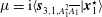
The numerical solution of the stability problem is as explained in Martinand et al. (Reference Martinand, Serre and Lueptow2009). Eigensolutions
 $(\boldsymbol{x}_{1},\unicode[STIX]{x1D714})$
of (2.10) at arbitrary
$(\boldsymbol{x}_{1},\unicode[STIX]{x1D714})$
of (2.10) at arbitrary
 $Ta$
are found using a spectral method where the radial shape functions are expanded over Chebyshev polynomials,
$Ta$
are found using a spectral method where the radial shape functions are expanded over Chebyshev polynomials,
 $N=24$
of which were found to be sufficient to ensure the convergence of the results. The solvability conditions of the systems of differential equations obtained by differentiating (2.10) with respect to
$N=24$
of which were found to be sufficient to ensure the convergence of the results. The solvability conditions of the systems of differential equations obtained by differentiating (2.10) with respect to
 $k$
,
$k$
,
 $n$
and
$n$
and
 $Ta$
lead to the several partial derivatives of the frequency (
$Ta$
lead to the several partial derivatives of the frequency (
 $\unicode[STIX]{x2202}_{k}\unicode[STIX]{x1D714}$
,
$\unicode[STIX]{x2202}_{k}\unicode[STIX]{x1D714}$
,
 $\unicode[STIX]{x2202}_{n}\unicode[STIX]{x1D714}$
,
$\unicode[STIX]{x2202}_{n}\unicode[STIX]{x1D714}$
,
 $\unicode[STIX]{x2202}_{k}^{2}\unicode[STIX]{x1D714}$
,
$\unicode[STIX]{x2202}_{k}^{2}\unicode[STIX]{x1D714}$
,
 $\unicode[STIX]{x2202}_{n}^{2}\unicode[STIX]{x1D714}$
,
$\unicode[STIX]{x2202}_{n}^{2}\unicode[STIX]{x1D714}$
,
 $\unicode[STIX]{x2202}_{k}\unicode[STIX]{x2202}_{n}\unicode[STIX]{x1D714}$
,
$\unicode[STIX]{x2202}_{k}\unicode[STIX]{x2202}_{n}\unicode[STIX]{x1D714}$
,
 $\unicode[STIX]{x2202}_{Ta}\unicode[STIX]{x1D714}$
and
$\unicode[STIX]{x2202}_{Ta}\unicode[STIX]{x1D714}$
and
 $\unicode[STIX]{x2202}_{Ta}^{2}\unicode[STIX]{x1D714}$
) and of the eigenvector (
$\unicode[STIX]{x2202}_{Ta}^{2}\unicode[STIX]{x1D714}$
) and of the eigenvector (
 $\unicode[STIX]{x2202}_{k}\boldsymbol{x}_{1}$
,
$\unicode[STIX]{x2202}_{k}\boldsymbol{x}_{1}$
,
 $\unicode[STIX]{x2202}_{n}\boldsymbol{x}_{1}$
,
$\unicode[STIX]{x2202}_{n}\boldsymbol{x}_{1}$
,
 $\unicode[STIX]{x2202}_{Ta}\boldsymbol{x}_{1}$
and
$\unicode[STIX]{x2202}_{Ta}\boldsymbol{x}_{1}$
and
 $\unicode[STIX]{x2202}_{Ta}^{2}\boldsymbol{x}_{1}$
) required by the linear and nonlinear analyses. The critical conditions
$\unicode[STIX]{x2202}_{Ta}^{2}\boldsymbol{x}_{1}$
) required by the linear and nonlinear analyses. The critical conditions
 $(k^{crit},n^{crit},Ta^{crit})$
of the most unstable mode
$(k^{crit},n^{crit},Ta^{crit})$
of the most unstable mode
 $(\boldsymbol{x}_{1}^{crit},\unicode[STIX]{x1D714}^{crit})$
are then found using a Newton–Raphson method so that
$(\boldsymbol{x}_{1}^{crit},\unicode[STIX]{x1D714}^{crit})$
are then found using a Newton–Raphson method so that
 $\text{Im}(\unicode[STIX]{x1D714})$
is minimized as a function of
$\text{Im}(\unicode[STIX]{x1D714})$
is minimized as a function of
 $k$
real and
$k$
real and
 $n$
integer and vanishes as a function of
$n$
integer and vanishes as a function of
 $Ta$
. The radial shape function is arbitrarily normalized by
$Ta$
. The radial shape function is arbitrarily normalized by
 $$\begin{eqnarray}\langle {\mathcal{B}}\boldsymbol{x}_{1}|\boldsymbol{x}_{1}^{\star }\rangle =1,\end{eqnarray}$$
where
 $\boldsymbol{x}_{1}^{\star }$
is the adjoint solution of eigenproblem (2.10) and
$\boldsymbol{x}_{1}^{\star }$
is the adjoint solution of eigenproblem (2.10) and
 $\langle \cdot |\cdot \rangle$
a semi-inner product purpose-built for the numerical discretization used. For complete spatial fields
$\langle \cdot |\cdot \rangle$
a semi-inner product purpose-built for the numerical discretization used. For complete spatial fields
 $\boldsymbol{X}(r,\unicode[STIX]{x1D703},z)$
, expanded as Fourier modes in
$\boldsymbol{X}(r,\unicode[STIX]{x1D703},z)$
, expanded as Fourier modes in
 $z$
and
$z$
and
 $\unicode[STIX]{x1D703}$
, this semi-inner product is generalized to
$\unicode[STIX]{x1D703}$
, this semi-inner product is generalized to
 $$\begin{eqnarray}\langle \boldsymbol{X}|\boldsymbol{X}^{\prime \star }\rangle =\unicode[STIX]{x1D6FF}_{k\,k^{\prime }}\unicode[STIX]{x1D6FF}_{n\,n^{\prime }}\langle \boldsymbol{x}|\boldsymbol{x}^{\prime \,\star }\rangle ,\end{eqnarray}$$
where
 $\unicode[STIX]{x1D6FF}$
is the Kronecker delta, while
$\unicode[STIX]{x1D6FF}$
is the Kronecker delta, while
 $k$
and
$k$
and
 $k^{\prime }$
, and
$k^{\prime }$
, and
 $n$
and
$n$
and
 $n^{\prime }$
are the axial and azimuthal wavenumbers of
$n^{\prime }$
are the axial and azimuthal wavenumbers of
 $\boldsymbol{X}$
and
$\boldsymbol{X}$
and
 $\boldsymbol{X}^{\prime }$
, respectively.
$\boldsymbol{X}^{\prime }$
, respectively.
2.3 Weakly nonlinear analysis
Building on the linear stability analysis, the weakly nonlinear behaviour of the convective instabilities is now considered. First, this analysis leads to the amplitude modulating the linear instability (2.9), as the solution of an amplitude equation. In addition, this analysis also leads to a hierarchy of corrections to the linear instability. The complex amplitude equation and the corrections are obtained in a classical fashion, detailed in appendix C, the results of which are summarized below. Assuming the existence of a critical Taylor number
 $Ta^{crit}$
above which the flow becomes linearly unstable leads to the expansion of
$Ta^{crit}$
above which the flow becomes linearly unstable leads to the expansion of
 $Ta$
about this critical condition as
$Ta$
about this critical condition as
 $$\begin{eqnarray}\unicode[STIX]{x0394}Ta=Ta-Ta^{crit}=\unicode[STIX]{x1D716}^{2}Ta_{2},\end{eqnarray}$$
assuming
 $\unicode[STIX]{x1D716}$
is small, and the physical fields
$\unicode[STIX]{x1D716}$
is small, and the physical fields
 $\boldsymbol{X}=(\boldsymbol{V},Q)^{t}=(U,V,W,Q)^{t}$
as
$\boldsymbol{X}=(\boldsymbol{V},Q)^{t}=(U,V,W,Q)^{t}$
as
 $$\begin{eqnarray}\boldsymbol{X}=\boldsymbol{X}_{0}+\unicode[STIX]{x1D716}\boldsymbol{X}_{1}+\unicode[STIX]{x1D716}^{2}\boldsymbol{X}_{2}+\unicode[STIX]{x1D716}^{3}\boldsymbol{X}_{3}+\cdots \,.\end{eqnarray}$$
A hierarchy of slow temporal variables related to the physical ones,
 $t_{i}=\unicode[STIX]{x1D716}^{i}t$
, are introduced, replacing the time derivative
$t_{i}=\unicode[STIX]{x1D716}^{i}t$
, are introduced, replacing the time derivative
 $\unicode[STIX]{x2202}/\unicode[STIX]{x2202}t$
by the expansion
$\unicode[STIX]{x2202}/\unicode[STIX]{x2202}t$
by the expansion
 $$\begin{eqnarray}\frac{\unicode[STIX]{x2202}}{\unicode[STIX]{x2202}t}+\unicode[STIX]{x1D716}\frac{\unicode[STIX]{x2202}}{\unicode[STIX]{x2202}t_{1}}+\unicode[STIX]{x1D716}^{2}\frac{\unicode[STIX]{x2202}}{\unicode[STIX]{x2202}t_{2}}+\unicode[STIX]{x1D716}^{3}\frac{\unicode[STIX]{x2202}}{\unicode[STIX]{x2202}t_{3}}+\cdots \,.\end{eqnarray}$$
Expansions (2.13)–(2.15) are then inserted in (2.1)–(2.2), leading to a hierarchy of systems of partial differential equations, the resolutions of which are detailed in appendix C. System (2.5)–(2.6) with
 $Ta=Ta^{crit}$
is recovered at the zeroth order
$Ta=Ta^{crit}$
is recovered at the zeroth order
 $(\unicode[STIX]{x1D716}^{0})$
. The zeroth-order term in expansion (2.14) thus identifies with the base flow at critical conditions
$(\unicode[STIX]{x1D716}^{0})$
. The zeroth-order term in expansion (2.14) thus identifies with the base flow at critical conditions
 $\boldsymbol{X}_{0}^{crit}$
. The stability problem (2.8) with
$\boldsymbol{X}_{0}^{crit}$
. The stability problem (2.8) with
 $Ta=Ta^{crit}$
is recovered at the first order
$Ta=Ta^{crit}$
is recovered at the first order
 $(\unicode[STIX]{x1D716}^{1})$
, satisfied by the critical mode
$(\unicode[STIX]{x1D716}^{1})$
, satisfied by the critical mode
 $\boldsymbol{x}_{1}^{crit}\exp (\text{i}\unicode[STIX]{x1D713}^{crit})$
, with
$\boldsymbol{x}_{1}^{crit}\exp (\text{i}\unicode[STIX]{x1D713}^{crit})$
, with
 $\unicode[STIX]{x1D713}^{crit}=k^{crit}z+n^{crit}\unicode[STIX]{x1D703}-\unicode[STIX]{x1D714}^{crit}t$
, up to an arbitrary slowly varying small amplitude
$\unicode[STIX]{x1D713}^{crit}=k^{crit}z+n^{crit}\unicode[STIX]{x1D703}-\unicode[STIX]{x1D714}^{crit}t$
, up to an arbitrary slowly varying small amplitude
 $A=\unicode[STIX]{x1D716}A_{1}(t_{1},t_{2},t_{3},\ldots )$
:
$A=\unicode[STIX]{x1D716}A_{1}(t_{1},t_{2},t_{3},\ldots )$
:
 $$\begin{eqnarray}\unicode[STIX]{x1D716}\boldsymbol{X}_{1}=A\boldsymbol{x}_{1}^{crit}\exp (\text{i}\unicode[STIX]{x1D713}^{crit})+\text{c.c}.\end{eqnarray}$$
A first level of approximation of the perturbation
 $\boldsymbol{X}$
is obtained by truncating expansion (2.14) at the second order
$\boldsymbol{X}$
is obtained by truncating expansion (2.14) at the second order
 $(\unicode[STIX]{x1D716}^{2})$
. In addition to (2.16), it leads to a second-order correction to the instability:
$(\unicode[STIX]{x1D716}^{2})$
. In addition to (2.16), it leads to a second-order correction to the instability:
 $$\begin{eqnarray}\unicode[STIX]{x1D716}^{2}\boldsymbol{X}_{2}=\unicode[STIX]{x0394}Ta\boldsymbol{x}_{2,0,Ta_{2}}+A\overline{A}\boldsymbol{x}_{2,0,A_{1}\overline{A_{1}}}+[A^{2}\boldsymbol{x}_{2,2,A_{1}^{2}}\exp (2\text{i}\unicode[STIX]{x1D713}^{crit})+\text{c.c.}],\end{eqnarray}$$
where the radial shape functions
 $\boldsymbol{x}_{2,0,Ta_{2}}$
,
$\boldsymbol{x}_{2,0,Ta_{2}}$
,
 $\boldsymbol{x}_{2,0,A_{1}\overline{A_{1}}}$
and
$\boldsymbol{x}_{2,0,A_{1}\overline{A_{1}}}$
and
 $\boldsymbol{x}_{2,2,A_{1}^{2}}$
are obtained from the solution of system (C 16). Moreover, the solvability conditions of the second- and third-order problems yield a third-order amplitude equation satisfied by
$\boldsymbol{x}_{2,2,A_{1}^{2}}$
are obtained from the solution of system (C 16). Moreover, the solvability conditions of the second- and third-order problems yield a third-order amplitude equation satisfied by
 $A$
of the form
$A$
of the form
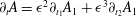 $\unicode[STIX]{x2202}_{t}A=\unicode[STIX]{x1D716}^{2}\unicode[STIX]{x2202}_{t_{1}}A_{1}+\unicode[STIX]{x1D716}^{3}\unicode[STIX]{x2202}_{t_{2}}A_{1}$
, and by combining equations (C 14), (C 29):
$\unicode[STIX]{x2202}_{t}A=\unicode[STIX]{x1D716}^{2}\unicode[STIX]{x2202}_{t_{1}}A_{1}+\unicode[STIX]{x1D716}^{3}\unicode[STIX]{x2202}_{t_{2}}A_{1}$
, and by combining equations (C 14), (C 29):
 $$\begin{eqnarray}\frac{\unicode[STIX]{x2202}A}{\unicode[STIX]{x2202}t}=-\text{i}\left.\frac{\unicode[STIX]{x2202}\unicode[STIX]{x1D714}}{\unicode[STIX]{x2202}Ta}\right|^{crit}\unicode[STIX]{x0394}Ta\,A+\unicode[STIX]{x1D707}A^{2}\overline{A},\end{eqnarray}$$
with the coefficient
 $\unicode[STIX]{x1D707}=\text{i}\langle \boldsymbol{s}_{3,1,A_{1}^{2}\overline{A_{1}}}|\boldsymbol{x}_{1}^{\star }\rangle$
computed from expression (C 23).
$\unicode[STIX]{x1D707}=\text{i}\langle \boldsymbol{s}_{3,1,A_{1}^{2}\overline{A_{1}}}|\boldsymbol{x}_{1}^{\star }\rangle$
computed from expression (C 23).
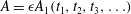
In the following, extension of the expansion (2.14) up to the fourth order and the related amplitude equation up to the fifth order in
 $\unicode[STIX]{x1D716}$
is necessary to obtain an accurate approximation of the instability and to address subcritical transitions. In addition to (2.16), (2.17), it leads to the third- and fourth-order corrections in (2.14):
$\unicode[STIX]{x1D716}$
is necessary to obtain an accurate approximation of the instability and to address subcritical transitions. In addition to (2.16), (2.17), it leads to the third- and fourth-order corrections in (2.14):
 $$\begin{eqnarray}\unicode[STIX]{x1D716}^{3}\boldsymbol{X}_{3}=\unicode[STIX]{x0394}TaA\boldsymbol{x}_{3,1,Ta_{2}\,A_{1}}\exp (\text{i}\unicode[STIX]{x1D713}^{crit})+A^{2}\overline{A}\boldsymbol{x}_{3,1,A_{1}^{2}\overline{A_{1}}}\exp (\text{i}\unicode[STIX]{x1D713}^{crit})+A^{3}\boldsymbol{x}_{3,3,A_{1}^{3}}\exp (3\text{i}\unicode[STIX]{x1D713}^{crit})+\text{c.c.},\end{eqnarray}$$
where the radial shape functions
 $\boldsymbol{x}_{3,1,Ta_{2}\,A_{1}}$
,
$\boldsymbol{x}_{3,1,Ta_{2}\,A_{1}}$
,
 $\boldsymbol{x}_{3,1,A_{1}^{2}\overline{A_{1}}}$
and
$\boldsymbol{x}_{3,1,A_{1}^{2}\overline{A_{1}}}$
and
 $\boldsymbol{x}_{3,3,A_{1}^{3}}$
are obtained from the solution of system (C 33), and
$\boldsymbol{x}_{3,3,A_{1}^{3}}$
are obtained from the solution of system (C 33), and
 $$\begin{eqnarray}\displaystyle \unicode[STIX]{x1D716}^{4}\boldsymbol{X}_{4} & = & \displaystyle \unicode[STIX]{x0394}Ta^{2}\boldsymbol{x}_{4,0,Ta_{2}^{2}}+\unicode[STIX]{x0394}TaA\overline{A}\boldsymbol{x}_{4,0,Ta_{2}\,A_{1}\overline{A_{1}}}+\unicode[STIX]{x0394}Ta[A^{2}\boldsymbol{x}_{4,2,Ta_{2}\,A_{1}^{2}}\exp (2\text{i}\unicode[STIX]{x1D713}^{crit})+\text{c.c.}]\nonumber\\ \displaystyle & & \displaystyle +\,A^{2}\overline{A}^{2}\boldsymbol{x}_{4,0,A_{1}^{2}\overline{A_{1}}^{2}}+[A^{3}\overline{A}\boldsymbol{x}_{4,2,A_{1}^{3}\overline{A_{1}}}\exp (2\text{i}\unicode[STIX]{x1D713}^{crit})+\text{c.c.}]\nonumber\\ \displaystyle & & \displaystyle +\,[A^{4}\boldsymbol{x}_{4,4,A_{1}^{4}}\exp (4\text{i}\unicode[STIX]{x1D713}^{crit})+\text{c.c.}],\end{eqnarray}$$
where the radial shape functions
 $\boldsymbol{x}_{4,0,Ta_{2}^{2}}$
,
$\boldsymbol{x}_{4,0,Ta_{2}^{2}}$
,
 $\boldsymbol{x}_{4,0,Ta_{2}\,A_{1}\overline{A_{1}}}$
,
$\boldsymbol{x}_{4,0,Ta_{2}\,A_{1}\overline{A_{1}}}$
,
 $\boldsymbol{x}_{4,2,Ta_{2}\,A_{1}^{2}}$
,
$\boldsymbol{x}_{4,2,Ta_{2}\,A_{1}^{2}}$
,
 $\boldsymbol{x}_{4,0,A_{1}^{2}\overline{A_{1}}^{2}}$
,
$\boldsymbol{x}_{4,0,A_{1}^{2}\overline{A_{1}}^{2}}$
,
 $\boldsymbol{x}_{4,2,A_{1}^{3}\overline{A_{1}}}$
and
$\boldsymbol{x}_{4,2,A_{1}^{3}\overline{A_{1}}}$
and
 $\boldsymbol{x}_{4,4,A_{1}^{4}}$
are obtained from the solution of system (C 54). The addition of the solvability conditions of the fourth- and fifth-order systems yields a fifth-order amplitude equation satisfied by
$\boldsymbol{x}_{4,4,A_{1}^{4}}$
are obtained from the solution of system (C 54). The addition of the solvability conditions of the fourth- and fifth-order systems yields a fifth-order amplitude equation satisfied by
 $A$
of the form
$A$
of the form
 $\unicode[STIX]{x2202}_{t}A=\unicode[STIX]{x1D716}^{2}\unicode[STIX]{x2202}_{t_{1}}A_{1}+\unicode[STIX]{x1D716}^{3}\unicode[STIX]{x2202}_{t_{2}}A_{1}+\unicode[STIX]{x1D716}^{4}\unicode[STIX]{x2202}_{t_{3}}A_{1}+\unicode[STIX]{x1D716}^{5}\unicode[STIX]{x2202}_{t_{4}}A_{1}$
, and by combining (C 14), (C 29), (C 52) and (C 66),
$\unicode[STIX]{x2202}_{t}A=\unicode[STIX]{x1D716}^{2}\unicode[STIX]{x2202}_{t_{1}}A_{1}+\unicode[STIX]{x1D716}^{3}\unicode[STIX]{x2202}_{t_{2}}A_{1}+\unicode[STIX]{x1D716}^{4}\unicode[STIX]{x2202}_{t_{3}}A_{1}+\unicode[STIX]{x1D716}^{5}\unicode[STIX]{x2202}_{t_{4}}A_{1}$
, and by combining (C 14), (C 29), (C 52) and (C 66),
 $$\begin{eqnarray}\frac{\unicode[STIX]{x2202}A}{\unicode[STIX]{x2202}t}=-\text{i}\left(\left.\frac{\unicode[STIX]{x2202}\unicode[STIX]{x1D714}}{\unicode[STIX]{x2202}Ta}\right|^{crit}\unicode[STIX]{x0394}Ta+\frac{1}{2}\left.\frac{\unicode[STIX]{x2202}^{2}\unicode[STIX]{x1D714}}{\unicode[STIX]{x2202}Ta^{2}}\right|^{crit}\unicode[STIX]{x0394}Ta^{2}\right)A+(\unicode[STIX]{x1D707}+\unicode[STIX]{x1D708}\unicode[STIX]{x0394}Ta)A^{2}\overline{A}+\unicode[STIX]{x1D712}A^{3}\overline{A}^{2},\end{eqnarray}$$
with the coefficients
 $\unicode[STIX]{x1D707}=\text{i}\langle \boldsymbol{s}_{3,1,A_{1}^{2}\overline{A_{1}}}|\boldsymbol{x}_{1}^{\star }\rangle$
,
$\unicode[STIX]{x1D707}=\text{i}\langle \boldsymbol{s}_{3,1,A_{1}^{2}\overline{A_{1}}}|\boldsymbol{x}_{1}^{\star }\rangle$
,
 $\unicode[STIX]{x1D708}=\text{i}\langle \boldsymbol{s}_{5,1,Ta_{2}\,A_{1}^{2}\overline{A_{1}}}|\boldsymbol{x}_{1}^{\star }\rangle$
and
$\unicode[STIX]{x1D708}=\text{i}\langle \boldsymbol{s}_{5,1,Ta_{2}\,A_{1}^{2}\overline{A_{1}}}|\boldsymbol{x}_{1}^{\star }\rangle$
and
 $\unicode[STIX]{x1D712}=\text{i}\langle \boldsymbol{s}_{5,1,A_{1}^{3}\overline{A_{1}}^{2}}|\boldsymbol{x}_{1}^{\star }\rangle$
computed from expressions (C 23), (C 60) and (C 62), respectively. To limit the amount of calculation, expansion (2.14) has not been continued to higher order, though using the fifth-order amplitude equation together with the fourth-order truncation of (2.14) is somewhat arbitrary.
$\unicode[STIX]{x1D712}=\text{i}\langle \boldsymbol{s}_{5,1,A_{1}^{3}\overline{A_{1}}^{2}}|\boldsymbol{x}_{1}^{\star }\rangle$
computed from expressions (C 23), (C 60) and (C 62), respectively. To limit the amount of calculation, expansion (2.14) has not been continued to higher order, though using the fifth-order amplitude equation together with the fourth-order truncation of (2.14) is somewhat arbitrary.
The discussion on the weakly nonlinear analysis in § 6 below is based on replacing the amplitude
 $A$
by
$A$
by
 $$\begin{eqnarray}A=|A|\exp (\unicode[STIX]{x1D70E}_{nonlin}t-\text{i}\unicode[STIX]{x1D6FF}\unicode[STIX]{x1D714}_{nonlin}t),\end{eqnarray}$$
where
 $|A|$
is the modulus of the amplitude,
$|A|$
is the modulus of the amplitude,
 $\unicode[STIX]{x1D6FF}\unicode[STIX]{x1D714}_{nonlin}$
is a correction to the real frequency at marginal conditions
$\unicode[STIX]{x1D6FF}\unicode[STIX]{x1D714}_{nonlin}$
is a correction to the real frequency at marginal conditions
 $\unicode[STIX]{x1D714}^{crit}$
, and
$\unicode[STIX]{x1D714}^{crit}$
, and
 $\unicode[STIX]{x1D70E}_{nonlin}$
is a temporal nonlinear growth rate. Inserting ansatz (2.22) in the third- or fifth-order amplitude equations ((2.18) or (2.21), respectively) yields the expressions for
$\unicode[STIX]{x1D70E}_{nonlin}$
is a temporal nonlinear growth rate. Inserting ansatz (2.22) in the third- or fifth-order amplitude equations ((2.18) or (2.21), respectively) yields the expressions for
 $\unicode[STIX]{x1D6FF}\unicode[STIX]{x1D714}_{nonlin}$
and
$\unicode[STIX]{x1D6FF}\unicode[STIX]{x1D714}_{nonlin}$
and
 $\unicode[STIX]{x1D70E}_{nonlin}$
, combining the effect of the departure from the critical conditions,
$\unicode[STIX]{x1D70E}_{nonlin}$
, combining the effect of the departure from the critical conditions,
 $\unicode[STIX]{x0394}Ta=Ta-Ta^{crit}$
, with the nonlinearities due to the finite amplitude
$\unicode[STIX]{x0394}Ta=Ta-Ta^{crit}$
, with the nonlinearities due to the finite amplitude
 $|A|$
of the instability. More specifically, from the third-order amplitude equation (2.18) one obtains the nonlinear growth rate
$|A|$
of the instability. More specifically, from the third-order amplitude equation (2.18) one obtains the nonlinear growth rate
 $$\begin{eqnarray}\unicode[STIX]{x1D70E}_{nonlin,3}=\text{Im}\left(\left.\frac{\unicode[STIX]{x2202}\unicode[STIX]{x1D714}}{\unicode[STIX]{x2202}Ta}\right|^{crit}\right)\unicode[STIX]{x0394}Ta+\text{Re}(\unicode[STIX]{x1D707})|A|^{2},\end{eqnarray}$$
a linear form of
 $(|A|^{2},\unicode[STIX]{x0394}Ta)$
. From the fifth-order amplitude equation (2.21), one obtains
$(|A|^{2},\unicode[STIX]{x0394}Ta)$
. From the fifth-order amplitude equation (2.21), one obtains
 $$\begin{eqnarray}\displaystyle \unicode[STIX]{x1D70E}_{nonlin,5} & = & \displaystyle \text{Im}\left(\left.\frac{\unicode[STIX]{x2202}\unicode[STIX]{x1D714}}{\unicode[STIX]{x2202}Ta}\right|^{crit}\unicode[STIX]{x0394}Ta+\frac{1}{2}\left.\frac{\unicode[STIX]{x2202}^{2}\unicode[STIX]{x1D714}}{\unicode[STIX]{x2202}Ta^{2}}\right|^{crit}\unicode[STIX]{x0394}Ta^{2}\right)\nonumber\\ \displaystyle & & \displaystyle +\,\text{Re}(\unicode[STIX]{x1D707}+\unicode[STIX]{x1D708}\unicode[STIX]{x0394}Ta)|A|^{2}+\text{Re}(\unicode[STIX]{x1D712})|A|^{4},\end{eqnarray}$$
a quadratic form of
 $(|A|^{2},\unicode[STIX]{x0394}Ta)$
. Finding the modulus of the amplitude
$(|A|^{2},\unicode[STIX]{x0394}Ta)$
. Finding the modulus of the amplitude
 $|A|(\unicode[STIX]{x0394}Ta)$
cancelling the growth rates (2.23) or (2.24) yields the saturation level of the instabilities and their domain of existence in terms of
$|A|(\unicode[STIX]{x0394}Ta)$
cancelling the growth rates (2.23) or (2.24) yields the saturation level of the instabilities and their domain of existence in terms of
 $\unicode[STIX]{x0394}Ta$
.
$\unicode[STIX]{x0394}Ta$
.
3 Direct numerical simulations
Direct numerical simulations of (2.1), (2.2) are performed using a parallel multidomain pseudospectral method based on Chebyshev polynomials in radial and axial directions and Fourier modes in the azimuthal direction. Time integration is accomplished with a second-order backward implicit Euler scheme for the linear terms and a second-order explicit Adams–Bashforth scheme for the nonlinear terms. An improved projection algorithm is employed for velocity–pressure coupling (see Raspo et al. Reference Raspo, Hughes, Serre, Randriamampianina and Bontoux2002, for details). The continuity between the subdomains of the velocity and pressure fields is enforced using an influence matrix technique described in Fontaine, Poncet & Serre (Reference Fontaine, Poncet and Serre2014). Previous validation in Czarny et al. (Reference Czarny, Serre, Bontoux and Lueptow2002, Reference Czarny, Serre, Bontoux and Lueptow2003) and Serre et al. (Reference Serre, Sprague and Lueptow2008) has shown the mono-domain version of the code to be in close agreement with theory (Recktenwald et al. Reference Recktenwald, Lücke and Müller1993; Min & Lueptow Reference Min and Lueptow1994b ; Johnson & Lueptow Reference Johnson and Lueptow1997; Martinand et al. Reference Martinand, Serre and Lueptow2009) and measurements (Sobolik et al. Reference Sobolik, Izrar, Lusseyran and Skali2000). The multidomain version of the code has been verified with respect to a manufactured solution (Fontaine et al. Reference Fontaine, Poncet and Serre2014).
The present numerical simulations are performed for large aspect ratios up to
 $L/d=100$
, where
$L/d=100$
, where
 $L$
is the axial length of the domain. The calculations use up to
$L$
is the axial length of the domain. The calculations use up to
 $10$
axial subdomains in order to address configurations with large aspect ratio. The meridional mesh grid is defined by the Gauss–Lobatto collocation points, with
$10$
axial subdomains in order to address configurations with large aspect ratio. The meridional mesh grid is defined by the Gauss–Lobatto collocation points, with
 $n_{r}=21$
–
$n_{r}=21$
–
 $31$
points in the radial direction and
$31$
points in the radial direction and
 $n_{z}=21$
–
$n_{z}=21$
–
 $101$
points in each subdomain in the axial direction. For three-dimensional non-axisymmetric simulations,
$101$
points in each subdomain in the axial direction. For three-dimensional non-axisymmetric simulations,
 $n_{\unicode[STIX]{x1D703}}=12$
–
$n_{\unicode[STIX]{x1D703}}=12$
–
 $48$
equally spaced mesh points are used in the azimuthal direction. Though not shown here, these resolutions were checked to ensure numerical convergence of the solutions.
$48$
equally spaced mesh points are used in the azimuthal direction. Though not shown here, these resolutions were checked to ensure numerical convergence of the solutions.
Boundary conditions (2.2) are used at the inner and outer cylinders. Without axial flow (
 $\unicode[STIX]{x1D6FD}=0$
), free-slip boundary conditions together with impermeability are used at the axial ends of the annulus. These boundary conditions are complicated by the axial flow entering and exiting the flow domain (
$\unicode[STIX]{x1D6FD}=0$
), free-slip boundary conditions together with impermeability are used at the axial ends of the annulus. These boundary conditions are complicated by the axial flow entering and exiting the flow domain (
 $\unicode[STIX]{x1D6FD}\neq 0$
). The velocity profile expressed in § 2.1, encompassing the azimuthal, axial and radial laminar flows, is then imposed at the inlet. A buffer region of length
$\unicode[STIX]{x1D6FD}\neq 0$
). The velocity profile expressed in § 2.1, encompassing the azimuthal, axial and radial laminar flows, is then imposed at the inlet. A buffer region of length
 $0.1L$
, extending upstream from the exit of the domain, is used to exponentially damp the perturbations and recover the analytic base flow at the outlet.
$0.1L$
, extending upstream from the exit of the domain, is used to exponentially damp the perturbations and recover the analytic base flow at the outlet.
4 Laminar base flow
While the effect of the axial and azimuthal driving of the fluid on the base flow is straightforward, because
 $\unicode[STIX]{x1D6FD}$
and
$\unicode[STIX]{x1D6FD}$
and
 $Ta$
only appear through a multiplicative constant in the axial velocity in expressions (A 1)–(A 4), the interplay between the radial flow (
$Ta$
only appear through a multiplicative constant in the axial velocity in expressions (A 1)–(A 4), the interplay between the radial flow (
 $\unicode[STIX]{x1D6FC}$
) and the radius ratio (
$\unicode[STIX]{x1D6FC}$
) and the radius ratio (
 $\unicode[STIX]{x1D702}$
) is less clear because
$\unicode[STIX]{x1D702}$
) is less clear because
 $\unicode[STIX]{x1D6FC}$
appears in exponents of
$\unicode[STIX]{x1D6FC}$
appears in exponents of
 $r$
in the radial dependence of the azimuthal and axial velocity components. Figure 2 depicts the combined effects of
$r$
in the radial dependence of the azimuthal and axial velocity components. Figure 2 depicts the combined effects of
 $\unicode[STIX]{x1D702}$
and
$\unicode[STIX]{x1D702}$
and
 $\unicode[STIX]{x1D6FC}$
on the base flow. Each column includes three radius ratios
$\unicode[STIX]{x1D6FC}$
on the base flow. Each column includes three radius ratios
 $\unicode[STIX]{x1D702}=0.85$
,
$\unicode[STIX]{x1D702}=0.85$
,
 $0.55$
and
$0.55$
and
 $0.25$
, from top to bottom. The left column shows radial inflow (
$0.25$
, from top to bottom. The left column shows radial inflow (
 $\unicode[STIX]{x1D6FC}<0$
); the middle column shows no radial flow (
$\unicode[STIX]{x1D6FC}<0$
); the middle column shows no radial flow (
 $\unicode[STIX]{x1D6FC}=0$
); the right column shows radial outflow (
$\unicode[STIX]{x1D6FC}=0$
); the right column shows radial outflow (
 $\unicode[STIX]{x1D6FC}>0$
). Note that the horizontal vectors are a combination of the radial and azimuthal flows, depicted for
$\unicode[STIX]{x1D6FC}>0$
). Note that the horizontal vectors are a combination of the radial and azimuthal flows, depicted for
 $Ta=30$
, which is significantly below the typical critical thresholds for unstable flow that will be obtained in the next section. The azimuthal flow is therefore weaker compared to the radial flow than what it would be close to critical conditions. Figure 2 only addresses variations in
$Ta=30$
, which is significantly below the typical critical thresholds for unstable flow that will be obtained in the next section. The azimuthal flow is therefore weaker compared to the radial flow than what it would be close to critical conditions. Figure 2 only addresses variations in
 $\unicode[STIX]{x1D702}$
and
$\unicode[STIX]{x1D702}$
and
 $\unicode[STIX]{x1D6FC}$
. As is evident from the expression for
$\unicode[STIX]{x1D6FC}$
. As is evident from the expression for
 $W_{0}$
in (A 1)–(A 4), increasing (decreasing) the axial Reynolds number
$W_{0}$
in (A 1)–(A 4), increasing (decreasing) the axial Reynolds number
 $\unicode[STIX]{x1D6FD}$
will only increase (decrease) the magnitude of the axial velocity profile without modifying its radial shape.
$\unicode[STIX]{x1D6FD}$
will only increase (decrease) the magnitude of the axial velocity profile without modifying its radial shape.

Figure 2. Combined effects of
 $\unicode[STIX]{x1D702}$
and
$\unicode[STIX]{x1D702}$
and
 $\unicode[STIX]{x1D6FC}$
on the non-dimensional base flows for
$\unicode[STIX]{x1D6FC}$
on the non-dimensional base flows for
 $\unicode[STIX]{x1D6FD}=20$
and
$\unicode[STIX]{x1D6FD}=20$
and
 $Ta=30$
with (a)
$Ta=30$
with (a)
 $\unicode[STIX]{x1D702}=0.85$
and
$\unicode[STIX]{x1D702}=0.85$
and
 $\unicode[STIX]{x1D6FC}=-10$
, (b)
$\unicode[STIX]{x1D6FC}=-10$
, (b)
 $\unicode[STIX]{x1D702}=0.85$
and
$\unicode[STIX]{x1D702}=0.85$
and
 $\unicode[STIX]{x1D6FC}=0$
, (c)
$\unicode[STIX]{x1D6FC}=0$
, (c)
 $\unicode[STIX]{x1D702}=0.85$
and
$\unicode[STIX]{x1D702}=0.85$
and
 $\unicode[STIX]{x1D6FC}=10$
, (d)
$\unicode[STIX]{x1D6FC}=10$
, (d)
 $\unicode[STIX]{x1D702}=0.55$
and
$\unicode[STIX]{x1D702}=0.55$
and
 $\unicode[STIX]{x1D6FC}=-10$
, (e)
$\unicode[STIX]{x1D6FC}=-10$
, (e)
 $\unicode[STIX]{x1D702}=0.55$
and
$\unicode[STIX]{x1D702}=0.55$
and
 $\unicode[STIX]{x1D6FC}=0$
, (f)
$\unicode[STIX]{x1D6FC}=0$
, (f)
 $\unicode[STIX]{x1D702}=0.55$
and
$\unicode[STIX]{x1D702}=0.55$
and
 $\unicode[STIX]{x1D6FC}=10$
, (g)
$\unicode[STIX]{x1D6FC}=10$
, (g)
 $\unicode[STIX]{x1D702}=0.25$
and
$\unicode[STIX]{x1D702}=0.25$
and
 $\unicode[STIX]{x1D6FC}=-10$
, (h)
$\unicode[STIX]{x1D6FC}=-10$
, (h)
 $\unicode[STIX]{x1D702}=0.25$
and
$\unicode[STIX]{x1D702}=0.25$
and
 $\unicode[STIX]{x1D6FC}=0$
, (i)
$\unicode[STIX]{x1D6FC}=0$
, (i)
 $\unicode[STIX]{x1D702}=0.25$
and
$\unicode[STIX]{x1D702}=0.25$
and
 $\unicode[STIX]{x1D6FC}=10$
. Vertical vectors (blue online) depict
$\unicode[STIX]{x1D6FC}=10$
. Vertical vectors (blue online) depict
 $W_{0}$
; horizontal vectors (red online) depict
$W_{0}$
; horizontal vectors (red online) depict
 $(U_{0},V_{0})$
.
$(U_{0},V_{0})$
.
Some points about the base flow are evident from figure 2. First, since the radial Reynolds number
 $\unicode[STIX]{x1D6FC}$
, based on the conserved radial flux, is a constant throughout the entire domain, the radial velocities at the outer and inner cylinders are linked by
$\unicode[STIX]{x1D6FC}$
, based on the conserved radial flux, is a constant throughout the entire domain, the radial velocities at the outer and inner cylinders are linked by
 $U_{out}=\unicode[STIX]{x1D702}U_{in}$
. At fixed
$U_{out}=\unicode[STIX]{x1D702}U_{in}$
. At fixed
 $\unicode[STIX]{x1D6FC}$
(each column in figure 2), the radial flow becomes dramatically large as
$\unicode[STIX]{x1D6FC}$
(each column in figure 2), the radial flow becomes dramatically large as
 $\unicode[STIX]{x1D702}$
decreases because the radial flux must be maintained at the small circumference of the inner cylinder (figure 2
g,i). The radial flow clearly shifts, in the direction of this radial flow, the radial locations with the smallest radial gradient of azimuthal momentum and the maximum in the axial velocity profile, and this shift is amplified by decreasing
$\unicode[STIX]{x1D702}$
decreases because the radial flux must be maintained at the small circumference of the inner cylinder (figure 2
g,i). The radial flow clearly shifts, in the direction of this radial flow, the radial locations with the smallest radial gradient of azimuthal momentum and the maximum in the axial velocity profile, and this shift is amplified by decreasing
 $\unicode[STIX]{x1D702}$
.
$\unicode[STIX]{x1D702}$
.
Expressions (A 1) also help to explain figure 2 with respect to the radial variation of the azimuthal velocity
 $V_{0}(r)$
. As
$V_{0}(r)$
. As
 $\unicode[STIX]{x1D702}\rightarrow 1$
, both
$\unicode[STIX]{x1D702}\rightarrow 1$
, both
 $r_{in}$
and
$r_{in}$
and
 $r_{out}$
tend to infinity. Thus, in the expression for
$r_{out}$
tend to infinity. Thus, in the expression for
 $V_{0}(r)$
of (A 1), the last term proportional
$V_{0}(r)$
of (A 1), the last term proportional
 $r^{\unicode[STIX]{x1D6FC}+1}$
dominates if
$r^{\unicode[STIX]{x1D6FC}+1}$
dominates if
 $\unicode[STIX]{x1D6FC}>-2$
; otherwise the first term proportional to
$\unicode[STIX]{x1D6FC}>-2$
; otherwise the first term proportional to
 $1/r$
dominates. Consequently, the azimuthal velocity profile
$1/r$
dominates. Consequently, the azimuthal velocity profile
 $V_{0}(r)$
evolves quasilinearly between
$V_{0}(r)$
evolves quasilinearly between
 $1$
and
$1$
and
 $0$
at
$0$
at
 $r_{in}$
and
$r_{in}$
and
 $r_{out}$
, respectively, for the case of a narrow gap in figure 2(a–c). On the other hand, as
$r_{out}$
, respectively, for the case of a narrow gap in figure 2(a–c). On the other hand, as
 $\unicode[STIX]{x1D702}\rightarrow 0$
,
$\unicode[STIX]{x1D702}\rightarrow 0$
,
 $r_{in}\rightarrow 0$
. In the expression for
$r_{in}\rightarrow 0$
. In the expression for
 $V_{0}$
of (A 1), the last term proportional
$V_{0}$
of (A 1), the last term proportional
 $r^{\unicode[STIX]{x1D6FC}+1}$
then dominates if
$r^{\unicode[STIX]{x1D6FC}+1}$
then dominates if
 $\unicode[STIX]{x1D6FC}<-2$
. The combination of both a small
$\unicode[STIX]{x1D6FC}<-2$
. The combination of both a small
 $\unicode[STIX]{x1D702}$
and a negative
$\unicode[STIX]{x1D702}$
and a negative
 $\unicode[STIX]{x1D6FC}$
leads to an azimuthal velocity profile
$\unicode[STIX]{x1D6FC}$
leads to an azimuthal velocity profile
 $V_{0}(r)$
exhibiting a very strong curvature, i.e. a large
$V_{0}(r)$
exhibiting a very strong curvature, i.e. a large
 $|\unicode[STIX]{x2202}_{r}^{2}V_{0}|$
, which is particularly evident in figure 2(g), where
$|\unicode[STIX]{x2202}_{r}^{2}V_{0}|$
, which is particularly evident in figure 2(g), where
 $V_{0}(r)$
scales like
$V_{0}(r)$
scales like
 $r^{-9}$
as
$r^{-9}$
as
 $r\rightarrow r_{in}$
. Moreover, this azimuthal flow is always unstable by Rayleigh’s circulation criterion in the inviscid limit, i.e.
$r\rightarrow r_{in}$
. Moreover, this azimuthal flow is always unstable by Rayleigh’s circulation criterion in the inviscid limit, i.e.
 $rV_{0}(r)$
is always a decreasing function of
$rV_{0}(r)$
is always a decreasing function of
 $r$
. Consequently, pursuing a linear stability analysis of this base flow is legitimate.
$r$
. Consequently, pursuing a linear stability analysis of this base flow is legitimate.
5 Linear convective instabilities
The linear stability analysis yields the linear critical conditions
 $(Ta^{crit},k^{crit},n^{crit})$
, the eigenvector
$(Ta^{crit},k^{crit},n^{crit})$
, the eigenvector
 $\boldsymbol{x}_{1}^{crit}$
, and the related velocity and pressure fields of the linear marginal mode, up to an arbitrary multiplicative constant. To further quantitatively describe the vortices, the azimuthal and axial wavenumbers
$\boldsymbol{x}_{1}^{crit}$
, and the related velocity and pressure fields of the linear marginal mode, up to an arbitrary multiplicative constant. To further quantitatively describe the vortices, the azimuthal and axial wavenumbers
 $n^{crit}$
and
$n^{crit}$
and
 $k^{crit}$
are combined in the form of the effective wavelength of the vortices at critical conditions,
$k^{crit}$
are combined in the form of the effective wavelength of the vortices at critical conditions,
 $\unicode[STIX]{x1D706}^{crit}=2\unicode[STIX]{x03C0}(k^{crit\,2}+n^{crit\,2}/r_{centre}^{2})^{-1/2}$
, where
$\unicode[STIX]{x1D706}^{crit}=2\unicode[STIX]{x03C0}(k^{crit\,2}+n^{crit\,2}/r_{centre}^{2})^{-1/2}$
, where
 $r_{centre}$
is the radius (
$r_{centre}$
is the radius (
 $r_{in}$
and
$r_{in}$
and
 $r_{out}$
excepted) where the axial velocity
$r_{out}$
excepted) where the axial velocity
 $w_{1}^{crit}(r)$
vanishes, which corresponds to the radius of the centre of the vortices. This effective wavelength reflects the size of a vortex pair in the sense that it quantifies its spatial extent along the axial direction in the case of toroidal vortices or along the direction perpendicular to its thread(s) in the case of helical vortices. The size of the vortices is also characterized by their radial extent, essentially the degree to which they fill the gap width, which is accessed from the radial shape function of the instability, i.e. the eigenvectors
$w_{1}^{crit}(r)$
vanishes, which corresponds to the radius of the centre of the vortices. This effective wavelength reflects the size of a vortex pair in the sense that it quantifies its spatial extent along the axial direction in the case of toroidal vortices or along the direction perpendicular to its thread(s) in the case of helical vortices. The size of the vortices is also characterized by their radial extent, essentially the degree to which they fill the gap width, which is accessed from the radial shape function of the instability, i.e. the eigenvectors
 $\boldsymbol{x}_{1}^{crit}(r)$
. Positive and negative
$\boldsymbol{x}_{1}^{crit}(r)$
. Positive and negative
 $n^{crit}$
correspond to different structures of helical vortices. To further characterize these helical vortices, we adopt the vocabulary used to describe the thread of a screw, relating a pair of counter-rotating vortices to a crest and trough of a screw. First, a thread is characterized by its handedness, which is here defined with the convention that the axial base flow is upward and the azimuthal base flow anticlockwise when seen from above. The streamlines of the base flow (A 1)–(A 4) and flows in figure 2 are therefore right-handed. For
$n^{crit}$
correspond to different structures of helical vortices. To further characterize these helical vortices, we adopt the vocabulary used to describe the thread of a screw, relating a pair of counter-rotating vortices to a crest and trough of a screw. First, a thread is characterized by its handedness, which is here defined with the convention that the axial base flow is upward and the azimuthal base flow anticlockwise when seen from above. The streamlines of the base flow (A 1)–(A 4) and flows in figure 2 are therefore right-handed. For
 $n^{crit}>0$
, the helical vortices are left-handed, so that the thread crosses the streamlines of the base flow, and for
$n^{crit}>0$
, the helical vortices are left-handed, so that the thread crosses the streamlines of the base flow, and for
 $n^{crit}<0$
, the helical vortices are right-handed. A thread is also characterized by the number of starts, in this case the number of independent crests looping around the axis, which corresponds here to
$n^{crit}<0$
, the helical vortices are right-handed. A thread is also characterized by the number of starts, in this case the number of independent crests looping around the axis, which corresponds here to
 $|n^{crit}|$
.
$|n^{crit}|$
.
The spatial dependence of the radial velocity field of the critical instability
 $u_{1}^{crit}\exp (\text{i}k^{crit}z+\text{i}n^{crit}\unicode[STIX]{x1D703})$
(i.e. the radial velocity without the radial base flow
$u_{1}^{crit}\exp (\text{i}k^{crit}z+\text{i}n^{crit}\unicode[STIX]{x1D703})$
(i.e. the radial velocity without the radial base flow
 $U_{0}$
) is illustrated in figure 3 for the same values for
$U_{0}$
) is illustrated in figure 3 for the same values for
 $\unicode[STIX]{x1D702}$
,
$\unicode[STIX]{x1D702}$
,
 $\unicode[STIX]{x1D6FC}$
and
$\unicode[STIX]{x1D6FC}$
and
 $\unicode[STIX]{x1D6FD}$
shown in figure 2. Those modes are analytically obtained at the critical Taylor numbers
$\unicode[STIX]{x1D6FD}$
shown in figure 2. Those modes are analytically obtained at the critical Taylor numbers
 $Ta^{crit}$
, indicated in figure 3, and they should be observed for Taylor numbers just above these critical values. The two different colours for isosurfaces of radial velocity correspond directly to inflow and outflow regions between vortices if the radial base flow is ignored. The axial base flow is upward and, seen from above, the inner cylinder is rotating anticlockwise. For radial outflow (right column in figure 3), the instability is helical under these conditions, with
$Ta^{crit}$
, indicated in figure 3, and they should be observed for Taylor numbers just above these critical values. The two different colours for isosurfaces of radial velocity correspond directly to inflow and outflow regions between vortices if the radial base flow is ignored. The axial base flow is upward and, seen from above, the inner cylinder is rotating anticlockwise. For radial outflow (right column in figure 3), the instability is helical under these conditions, with
 $n^{crit}=1$
in all cases. The vortices fill the entire gap width. When there is no radial flow (middle column in figure 3), the instability is helical only in the case of the narrowest gap (figure 3
b), while the vortices in the wider gaps (figure 3
e,h) are toroidal. The helical and toroidal nature of the vortices does not change in the presence of the radial inflow (left column in figure 3), but the size of the vortices changes substantially for the cases of a wide gap, most evidently in figure 3(g), but also to some extent in figure 3(d). While in most situations the radial extent of the vortices, whether toroidal or helical, coincides with the radial width of the annular gap, the vortices in these two cases are smaller in both the radial and axial directions, and centred near the inner cylinder when a radial inflow is combined with a wide gap. This effect is all the more important because, at fixed
$n^{crit}=1$
in all cases. The vortices fill the entire gap width. When there is no radial flow (middle column in figure 3), the instability is helical only in the case of the narrowest gap (figure 3
b), while the vortices in the wider gaps (figure 3
e,h) are toroidal. The helical and toroidal nature of the vortices does not change in the presence of the radial inflow (left column in figure 3), but the size of the vortices changes substantially for the cases of a wide gap, most evidently in figure 3(g), but also to some extent in figure 3(d). While in most situations the radial extent of the vortices, whether toroidal or helical, coincides with the radial width of the annular gap, the vortices in these two cases are smaller in both the radial and axial directions, and centred near the inner cylinder when a radial inflow is combined with a wide gap. This effect is all the more important because, at fixed
 $\unicode[STIX]{x1D6FC}$
, the radial velocity of the base flow at the inner cylinder increases with the width of the gap, as shown in figure 2. This crowding of the vortex stack may be accounted for by two mechanisms, though these mechanisms are only speculative. The first mechanism is based on the suction at the inner cylinder aspiring the fluid out of the annulus, thereby advecting the vortices towards the inner cylinder and reducing their size. The other mechanism results from the radial gradient of the azimuthal shear of the base flow being strongly localized near the inner cylinder, as shown in figure 2(d,g). The instability could then be strongly sustained in this inner region while the outer region remains stable due to dominant viscous effects. This crowding of the vortex stack is not observed in the presence of a radial outflow as in figure 3(i). Figure 3 also shows that the critical conditions vary greatly with
$\unicode[STIX]{x1D6FC}$
, the radial velocity of the base flow at the inner cylinder increases with the width of the gap, as shown in figure 2. This crowding of the vortex stack may be accounted for by two mechanisms, though these mechanisms are only speculative. The first mechanism is based on the suction at the inner cylinder aspiring the fluid out of the annulus, thereby advecting the vortices towards the inner cylinder and reducing their size. The other mechanism results from the radial gradient of the azimuthal shear of the base flow being strongly localized near the inner cylinder, as shown in figure 2(d,g). The instability could then be strongly sustained in this inner region while the outer region remains stable due to dominant viscous effects. This crowding of the vortex stack is not observed in the presence of a radial outflow as in figure 3(i). Figure 3 also shows that the critical conditions vary greatly with
 $\unicode[STIX]{x1D702}$
and
$\unicode[STIX]{x1D702}$
and
 $\unicode[STIX]{x1D6FC}$
. For example,
$\unicode[STIX]{x1D6FC}$
. For example,
 $Ta^{crit}=79.4$
for
$Ta^{crit}=79.4$
for
 $\unicode[STIX]{x1D702}=0.55$
and
$\unicode[STIX]{x1D702}=0.55$
and
 $\unicode[STIX]{x1D6FC}=0$
, while
$\unicode[STIX]{x1D6FC}=0$
, while
 $Ta^{crit}=726.5$
for
$Ta^{crit}=726.5$
for
 $\unicode[STIX]{x1D702}=0.25$
and
$\unicode[STIX]{x1D702}=0.25$
and
 $\unicode[STIX]{x1D6FC}=-10$
. This suggests that the linear stability analysis is also an appropriate approach for performing a parametric study of these dramatic variations.
$\unicode[STIX]{x1D6FC}=-10$
. This suggests that the linear stability analysis is also an appropriate approach for performing a parametric study of these dramatic variations.

Figure 3. Linear modes of instabilities for
 $\unicode[STIX]{x1D6FD}=20$
and (a)
$\unicode[STIX]{x1D6FD}=20$
and (a)
 $\unicode[STIX]{x1D702}=0.85$
and
$\unicode[STIX]{x1D702}=0.85$
and
 $\unicode[STIX]{x1D6FC}=-10$
, (b)
$\unicode[STIX]{x1D6FC}=-10$
, (b)
 $\unicode[STIX]{x1D702}=0.85$
and
$\unicode[STIX]{x1D702}=0.85$
and
 $\unicode[STIX]{x1D6FC}=0$
, (c)
$\unicode[STIX]{x1D6FC}=0$
, (c)
 $\unicode[STIX]{x1D702}=0.85$
and
$\unicode[STIX]{x1D702}=0.85$
and
 $\unicode[STIX]{x1D6FC}=10$
, (d)
$\unicode[STIX]{x1D6FC}=10$
, (d)
 $\unicode[STIX]{x1D702}=0.55$
and
$\unicode[STIX]{x1D702}=0.55$
and
 $\unicode[STIX]{x1D6FC}=-10$
, (e)
$\unicode[STIX]{x1D6FC}=-10$
, (e)
 $\unicode[STIX]{x1D702}=0.55$
and
$\unicode[STIX]{x1D702}=0.55$
and
 $\unicode[STIX]{x1D6FC}=0$
, (f)
$\unicode[STIX]{x1D6FC}=0$
, (f)
 $\unicode[STIX]{x1D702}=0.55$
and
$\unicode[STIX]{x1D702}=0.55$
and
 $\unicode[STIX]{x1D6FC}=10$
, (g)
$\unicode[STIX]{x1D6FC}=10$
, (g)
 $\unicode[STIX]{x1D702}=0.25$
and
$\unicode[STIX]{x1D702}=0.25$
and
 $\unicode[STIX]{x1D6FC}=-10$
, (h)
$\unicode[STIX]{x1D6FC}=-10$
, (h)
 $\unicode[STIX]{x1D702}=0.25$
and
$\unicode[STIX]{x1D702}=0.25$
and
 $\unicode[STIX]{x1D6FC}=0$
, (i)
$\unicode[STIX]{x1D6FC}=0$
, (i)
 $\unicode[STIX]{x1D702}=0.25$
and
$\unicode[STIX]{x1D702}=0.25$
and
 $\unicode[STIX]{x1D6FC}=10$
. Isosurfaces of the radial velocity of the instability
$\unicode[STIX]{x1D6FC}=10$
. Isosurfaces of the radial velocity of the instability
 $U_{1}$
are shown at
$U_{1}$
are shown at
 $0.2$
(dark grey, red online) and
$0.2$
(dark grey, red online) and
 $-0.2$
(light grey, green online) of the maximum value. For all helical vortices,
$-0.2$
(light grey, green online) of the maximum value. For all helical vortices,
 $n^{crit}=1$
.
$n^{crit}=1$
.

Figure 4. Linear stability results for the most unstable convective mode as a function of the radial and axial Reynolds numbers
 $\unicode[STIX]{x1D6FC}$
and
$\unicode[STIX]{x1D6FC}$
and
 $\unicode[STIX]{x1D6FD}$
, at radius ratio
$\unicode[STIX]{x1D6FD}$
, at radius ratio
 $\unicode[STIX]{x1D702}=0.85$
(a,b),
$\unicode[STIX]{x1D702}=0.85$
(a,b),
 $\unicode[STIX]{x1D702}=0.55$
(c,d) and
$\unicode[STIX]{x1D702}=0.55$
(c,d) and
 $\unicode[STIX]{x1D702}=0.25$
(e,f). The colour scale corresponds to the critical azimuthal wavenumber
$\unicode[STIX]{x1D702}=0.25$
(e,f). The colour scale corresponds to the critical azimuthal wavenumber
 $n^{crit}$
. (a,c,e) Critical Taylor number
$n^{crit}$
. (a,c,e) Critical Taylor number
 $Ta^{crit}$
. (b,d,f) Effective wavelength of the vortices
$Ta^{crit}$
. (b,d,f) Effective wavelength of the vortices
 $\unicode[STIX]{x1D706}^{crit}=2\unicode[STIX]{x03C0}(k^{crit\,2}+n^{crit\,2}/r_{centre}^{2})^{-1/2}$
. The white circles correspond to the cases shown in figure 3. The black squares in (a) and (b) correspond to the cases shown in the insets below those panels. The white dotted lines show the intersections between this parameter range and the ones in figure 5 (
$\unicode[STIX]{x1D706}^{crit}=2\unicode[STIX]{x03C0}(k^{crit\,2}+n^{crit\,2}/r_{centre}^{2})^{-1/2}$
. The white circles correspond to the cases shown in figure 3. The black squares in (a) and (b) correspond to the cases shown in the insets below those panels. The white dotted lines show the intersections between this parameter range and the ones in figure 5 (
 $\unicode[STIX]{x1D6FD}=10$
). Note the range of
$\unicode[STIX]{x1D6FD}=10$
). Note the range of
 $\unicode[STIX]{x1D6FC}$
is limited to
$\unicode[STIX]{x1D6FC}$
is limited to
 $[-15,30]$
in plots (e,f) because the very large
$[-15,30]$
in plots (e,f) because the very large
 $Ta^{crit}$
obtained for large inflows would dwarf the rest of the plot.
$Ta^{crit}$
obtained for large inflows would dwarf the rest of the plot.
5.1 Parametric study
Results depicted in figure 4 expand upon previously published linear stability results, which were limited to
 $\unicode[STIX]{x1D702}=0.85$
,
$\unicode[STIX]{x1D702}=0.85$
,
 $-20\leqslant \unicode[STIX]{x1D6FC}\leqslant 20$
and
$-20\leqslant \unicode[STIX]{x1D6FC}\leqslant 20$
and
 $0\leqslant \unicode[STIX]{x1D6FD}\leqslant 50$
in Martinand et al. (Reference Martinand, Serre and Lueptow2009). In addition to extending the ranges of
$0\leqslant \unicode[STIX]{x1D6FD}\leqslant 50$
in Martinand et al. (Reference Martinand, Serre and Lueptow2009). In addition to extending the ranges of
 $\unicode[STIX]{x1D6FC}$
and
$\unicode[STIX]{x1D6FC}$
and
 $\unicode[STIX]{x1D6FD}$
, the main point is here to consider the influence of the radius ratio
$\unicode[STIX]{x1D6FD}$
, the main point is here to consider the influence of the radius ratio
 $\unicode[STIX]{x1D702}$
on the convective instabilities and to stress how, along with the radial flow, it strongly modifies these instabilities. Figure 4 shows the results of the linear stability analysis over the range
$\unicode[STIX]{x1D702}$
on the convective instabilities and to stress how, along with the radial flow, it strongly modifies these instabilities. Figure 4 shows the results of the linear stability analysis over the range
 $-30\leqslant \unicode[STIX]{x1D6FC}\leqslant 30$
and
$-30\leqslant \unicode[STIX]{x1D6FC}\leqslant 30$
and
 $0\leqslant \unicode[STIX]{x1D6FD}\leqslant 100$
for
$0\leqslant \unicode[STIX]{x1D6FD}\leqslant 100$
for
 $\unicode[STIX]{x1D702}=0.85$
(a,b),
$\unicode[STIX]{x1D702}=0.85$
(a,b),
 $0.55$
(c,d) and
$0.55$
(c,d) and
 $0.25$
(e,f). Figure 4(a,c,e) displays the critical Taylor number
$0.25$
(e,f). Figure 4(a,c,e) displays the critical Taylor number
 $Ta^{crit}$
for the instability of the laminar base flow. The critical azimuthal wavenumber
$Ta^{crit}$
for the instability of the laminar base flow. The critical azimuthal wavenumber
 $n^{crit}$
is indicated by the colour scale. The radial and axial Reynolds numbers
$n^{crit}$
is indicated by the colour scale. The radial and axial Reynolds numbers
 $\unicode[STIX]{x1D6FC}$
and
$\unicode[STIX]{x1D6FC}$
and
 $\unicode[STIX]{x1D6FD}$
strongly impact the critical conditions inferred from the linear stability analysis, depending on the radius ratio
$\unicode[STIX]{x1D6FD}$
strongly impact the critical conditions inferred from the linear stability analysis, depending on the radius ratio
 $\unicode[STIX]{x1D702}$
. Previous results at
$\unicode[STIX]{x1D702}$
. Previous results at
 $\unicode[STIX]{x1D702}=0.85$
(Martinand et al.
Reference Martinand, Serre and Lueptow2009), recovered and extended in figure 4(a), indicate that as the axial flow increases, the appearance of the centrifugal instabilities is postponed and the toroidal vortices (
$\unicode[STIX]{x1D702}=0.85$
(Martinand et al.
Reference Martinand, Serre and Lueptow2009), recovered and extended in figure 4(a), indicate that as the axial flow increases, the appearance of the centrifugal instabilities is postponed and the toroidal vortices (
 $n^{crit}=0$
) are superseded by helical vortices (
$n^{crit}=0$
) are superseded by helical vortices (
 $n^{crit}\neq 0$
). Moreover, the azimuthal wavenumber
$n^{crit}\neq 0$
). Moreover, the azimuthal wavenumber
 $n^{crit}$
, i.e. the number of starts of the helical vortices, increases with the axial flow. These helical vortices are always left-handed, as indicated by the positive values for
$n^{crit}$
, i.e. the number of starts of the helical vortices, increases with the axial flow. These helical vortices are always left-handed, as indicated by the positive values for
 $n^{crit}$
, consistent with previous results (see Snyder Reference Snyder1965; Chung & Astill Reference Chung and Astill1977; Ng & Turner Reference Ng and Turner1982; Lueptow et al.
Reference Lueptow, Docter and Min1992). Figure 4 confirms these findings for small gaps but demonstrates that the stabilizing effect of the axial flow is not as strong as
$n^{crit}$
, consistent with previous results (see Snyder Reference Snyder1965; Chung & Astill Reference Chung and Astill1977; Ng & Turner Reference Ng and Turner1982; Lueptow et al.
Reference Lueptow, Docter and Min1992). Figure 4 confirms these findings for small gaps but demonstrates that the stabilizing effect of the axial flow is not as strong as
 $\unicode[STIX]{x1D702}$
decreases. Figure 4(c,e) actually shows a very limited influence of
$\unicode[STIX]{x1D702}$
decreases. Figure 4(c,e) actually shows a very limited influence of
 $\unicode[STIX]{x1D6FD}$
on
$\unicode[STIX]{x1D6FD}$
on
 $Ta^{crit}$
. Moreover, figure 4(a,c,e) shows that in the presence of a radial outflow, an increasing axial flow eventually becomes destabilizing.
$Ta^{crit}$
. Moreover, figure 4(a,c,e) shows that in the presence of a radial outflow, an increasing axial flow eventually becomes destabilizing.
Figure 4(b,d,f) depicts the evolution of the effective wavelength of the vortices at critical conditions
 $\unicode[STIX]{x1D706}^{crit}$
. As would be expected for standard Taylor–Couette flow, in the absence of radial and axial flows, the axial wavenumber
$\unicode[STIX]{x1D706}^{crit}$
. As would be expected for standard Taylor–Couette flow, in the absence of radial and axial flows, the axial wavenumber
 $k^{crit}$
of the toroidal vortices is close to
$k^{crit}$
of the toroidal vortices is close to
 $\unicode[STIX]{x03C0}$
, so
$\unicode[STIX]{x03C0}$
, so
 $\unicode[STIX]{x1D706}^{crit}$
is close to
$\unicode[STIX]{x1D706}^{crit}$
is close to
 $2$
, corresponding to the axial extent of a vortex coinciding with the width of the annular gap, i.e. a stack of nearly circular counter-rotating vortices. For narrow gaps, as shown in figure 4(b), the effective wavelength of the vortices remains in a similar range, decreasing towards
$2$
, corresponding to the axial extent of a vortex coinciding with the width of the annular gap, i.e. a stack of nearly circular counter-rotating vortices. For narrow gaps, as shown in figure 4(b), the effective wavelength of the vortices remains in a similar range, decreasing towards
 $1.5$
, as the axial flow increases. The increase of
$1.5$
, as the axial flow increases. The increase of
 $n^{crit}$
, up to
$n^{crit}$
, up to
 $n^{crit}=21$
in figure 4(b), is offset by a decrease of
$n^{crit}=21$
in figure 4(b), is offset by a decrease of
 $k^{crit}$
. This last point reveals that it is mostly the inclination of the vortices with respect the axial direction that changes as
$k^{crit}$
. This last point reveals that it is mostly the inclination of the vortices with respect the axial direction that changes as
 $n^{crit}$
increases, as shown in the two insets of figure 4. Besides the inclination of the helical vortices, these insets and figure 4(b) show that for a small gap combined with a radial outflow, the azimuthal wavenumber abruptly increases beyond
$n^{crit}$
increases, as shown in the two insets of figure 4. Besides the inclination of the helical vortices, these insets and figure 4(b) show that for a small gap combined with a radial outflow, the azimuthal wavenumber abruptly increases beyond
 $\unicode[STIX]{x1D6FD}\approx 60$
. For example, at
$\unicode[STIX]{x1D6FD}\approx 60$
. For example, at
 $\unicode[STIX]{x1D6FC}=30$
,
$\unicode[STIX]{x1D6FC}=30$
,
 $n^{crit}$
jumps from
$n^{crit}$
jumps from
 $2$
at
$2$
at
 $\unicode[STIX]{x1D6FD}=55$
in the left inset to
$\unicode[STIX]{x1D6FD}=55$
in the left inset to
 $16$
at
$16$
at
 $\unicode[STIX]{x1D6FD}=65$
in the right inset. These high-
$\unicode[STIX]{x1D6FD}=65$
in the right inset. These high-
 $n^{crit}$
modes do not occur for larger gaps within the range of radial Reynolds numbers that was considered in figure 4(c–f).
$n^{crit}$
modes do not occur for larger gaps within the range of radial Reynolds numbers that was considered in figure 4(c–f).
The sensitivity of the azimuthal wavenumber
 $n^{crit}$
to the axial flow also strongly depends on the radius ratio: as
$n^{crit}$
to the axial flow also strongly depends on the radius ratio: as
 $\unicode[STIX]{x1D702}$
decreases, so does
$\unicode[STIX]{x1D702}$
decreases, so does
 $n^{crit}$
. Noting the vortices are helical at high axial Reynolds number
$n^{crit}$
. Noting the vortices are helical at high axial Reynolds number
 $\unicode[STIX]{x1D6FD}$
, a straightforward explanation would be that there is a maximum number of vortices with a cross-sectional aspect ratio close to one that could pack azimuthally within the annular gap, i.e. a maximum azimuthal wavenumber
$\unicode[STIX]{x1D6FD}$
, a straightforward explanation would be that there is a maximum number of vortices with a cross-sectional aspect ratio close to one that could pack azimuthally within the annular gap, i.e. a maximum azimuthal wavenumber
 $n_{max}(\unicode[STIX]{x1D702})$
. The limiting case corresponds to vortices aligned with the axial direction, based purely on a geometrical argument, without questioning the physical relevance of vortices aligned in the axial direction. This geometrical criterion leads to
$n_{max}(\unicode[STIX]{x1D702})$
. The limiting case corresponds to vortices aligned with the axial direction, based purely on a geometrical argument, without questioning the physical relevance of vortices aligned in the axial direction. This geometrical criterion leads to
 $n_{max}=\unicode[STIX]{x03C0}(1+\unicode[STIX]{x1D702})/2(1-\unicode[STIX]{x1D702})$
. For
$n_{max}=\unicode[STIX]{x03C0}(1+\unicode[STIX]{x1D702})/2(1-\unicode[STIX]{x1D702})$
. For
 $\unicode[STIX]{x1D702}=0.85$
, 0.55 and 0.25,
$\unicode[STIX]{x1D702}=0.85$
, 0.55 and 0.25,
 $n_{max}(\unicode[STIX]{x1D702})\approx 20$
, 6 and 3, respectively, consistent with the situation as
$n_{max}(\unicode[STIX]{x1D702})\approx 20$
, 6 and 3, respectively, consistent with the situation as
 $\unicode[STIX]{x1D702}$
decreases in figure 4.
$\unicode[STIX]{x1D702}$
decreases in figure 4.
Focusing now on the effect of the radial flow, a radial in- or outflow has also been found to be stabilizing in narrow gaps, except for moderate outflows, which are slightly destabilizing (Min & Lueptow Reference Min and Lueptow1994b
; Johnson & Lueptow Reference Johnson and Lueptow1997; Serre et al.
Reference Serre, Sprague and Lueptow2008; Martinand et al.
Reference Martinand, Serre and Lueptow2009), as is evident in figure 1. Moreover, a radial inflow is generally more stabilizing than the equivalent outflow. It is clear from figure 4(c,e) that the impact of a radial flow on the stability is increasingly important as
 $\unicode[STIX]{x1D702}$
decreases, with a spectacular stabilization associated with a strong radial inflow. For example, without axial flow (
$\unicode[STIX]{x1D702}$
decreases, with a spectacular stabilization associated with a strong radial inflow. For example, without axial flow (
 $\unicode[STIX]{x1D6FD}=0$
),
$\unicode[STIX]{x1D6FD}=0$
),
 $Ta^{crit}=1137$
at
$Ta^{crit}=1137$
at
 $\unicode[STIX]{x1D6FC}=-30$
for
$\unicode[STIX]{x1D6FC}=-30$
for
 $\unicode[STIX]{x1D702}=0.55$
, compared to
$\unicode[STIX]{x1D702}=0.55$
, compared to
 $Ta^{crit}=69.5$
without radial flow; similarly,
$Ta^{crit}=69.5$
without radial flow; similarly,
 $Ta^{crit}=4109$
at
$Ta^{crit}=4109$
at
 $\unicode[STIX]{x1D6FC}=-30$
for
$\unicode[STIX]{x1D6FC}=-30$
for
 $\unicode[STIX]{x1D702}=0.25$
(not shown in figure 4
e), compared to
$\unicode[STIX]{x1D702}=0.25$
(not shown in figure 4
e), compared to
 $Ta^{crit}=78.8$
without radial flow. Moreover, a radial inflow tends to very substantially increase
$Ta^{crit}=78.8$
without radial flow. Moreover, a radial inflow tends to very substantially increase
 $k^{crit}$
and decrease
$k^{crit}$
and decrease
 $\unicode[STIX]{x1D706}^{crit}$
accordingly, this effect being further enhanced as
$\unicode[STIX]{x1D706}^{crit}$
accordingly, this effect being further enhanced as
 $\unicode[STIX]{x1D702}$
decreases, as shown in figure 4(d,f). For example, with no axial flow (
$\unicode[STIX]{x1D702}$
decreases, as shown in figure 4(d,f). For example, with no axial flow (
 $\unicode[STIX]{x1D6FD}=0$
),
$\unicode[STIX]{x1D6FD}=0$
),
 $\unicode[STIX]{x1D706}^{crit}=0.46$
at
$\unicode[STIX]{x1D706}^{crit}=0.46$
at
 $\unicode[STIX]{x1D6FC}=-30$
for
$\unicode[STIX]{x1D6FC}=-30$
for
 $\unicode[STIX]{x1D702}=0.55$
, compared to
$\unicode[STIX]{x1D702}=0.55$
, compared to
 $\unicode[STIX]{x1D706}^{crit}=1.99$
without radial flow;
$\unicode[STIX]{x1D706}^{crit}=1.99$
without radial flow;
 $\unicode[STIX]{x1D706}^{crit}=0.12$
at
$\unicode[STIX]{x1D706}^{crit}=0.12$
at
 $\unicode[STIX]{x1D6FC}=-30$
for
$\unicode[STIX]{x1D6FC}=-30$
for
 $\unicode[STIX]{x1D702}=0.25$
(not shown in figure 4
h), compared to
$\unicode[STIX]{x1D702}=0.25$
(not shown in figure 4
h), compared to
 $\unicode[STIX]{x1D706}^{crit}=1.94$
without radial flow. A similar trend is observed to a lesser extent in the presence of a radial outflow for
$\unicode[STIX]{x1D706}^{crit}=1.94$
without radial flow. A similar trend is observed to a lesser extent in the presence of a radial outflow for
 $\unicode[STIX]{x1D702}=0.55$
but not at
$\unicode[STIX]{x1D702}=0.55$
but not at
 $\unicode[STIX]{x1D702}=0.25$
, whose specific behaviour will be addressed later in § 5.2.
$\unicode[STIX]{x1D702}=0.25$
, whose specific behaviour will be addressed later in § 5.2.
Though not shown here, the phase speed
 $v_{\unicode[STIX]{x1D719}}^{crit}=\unicode[STIX]{x1D714}^{crit}/k^{crit}$
and the axial group velocity
$v_{\unicode[STIX]{x1D719}}^{crit}=\unicode[STIX]{x1D714}^{crit}/k^{crit}$
and the axial group velocity
 $v_{g}^{crit}=\unicode[STIX]{x2202}_{k}\unicode[STIX]{x1D714}^{crit}$
are comparable, when re-expressed dimensionally, to the mean axial velocity
$v_{g}^{crit}=\unicode[STIX]{x2202}_{k}\unicode[STIX]{x1D714}^{crit}$
are comparable, when re-expressed dimensionally, to the mean axial velocity
 $\overline{W}$
, as is already known to occur with no radial flow (Lueptow et al.
Reference Lueptow, Docter and Min1992; Recktenwald et al.
Reference Recktenwald, Lücke and Müller1993; Wereley & Lueptow Reference Wereley and Lueptow1999).
$\overline{W}$
, as is already known to occur with no radial flow (Lueptow et al.
Reference Lueptow, Docter and Min1992; Recktenwald et al.
Reference Recktenwald, Lücke and Müller1993; Wereley & Lueptow Reference Wereley and Lueptow1999).
5.2 Wide gaps and large helical vortices
It is clear from results in figure 4 that the interplay between the radial flow and the width of the gap is key to the nature of the instability. Cases with wide gaps (small
 $\unicode[STIX]{x1D702}$
) are seldom addressed in the literature, the main reason being the difficulty in building an experimental rig or performing a numerical simulation with both a large gap and an aspect ratio large enough to avoid end wall effects. Moreover, previous results (Martinand, Serre & Lueptow Reference Martinand, Serre and Lueptow2014) tend to show that the transition scenario with wide gaps is not as clearly defined as with narrow gaps, even for situations with no radial or axial flow. Thus, it seems appropriate to use extra care when varying the radius ratio in combination with a radial and/or axial flow. With this limitation in mind, figure 5 further details some of the features observed when a wide gap (small
$\unicode[STIX]{x1D702}$
) are seldom addressed in the literature, the main reason being the difficulty in building an experimental rig or performing a numerical simulation with both a large gap and an aspect ratio large enough to avoid end wall effects. Moreover, previous results (Martinand, Serre & Lueptow Reference Martinand, Serre and Lueptow2014) tend to show that the transition scenario with wide gaps is not as clearly defined as with narrow gaps, even for situations with no radial or axial flow. Thus, it seems appropriate to use extra care when varying the radius ratio in combination with a radial and/or axial flow. With this limitation in mind, figure 5 further details some of the features observed when a wide gap (small
 $\unicode[STIX]{x1D702}$
) is combined with a radial flow. First, a radial inflow (
$\unicode[STIX]{x1D702}$
) is combined with a radial flow. First, a radial inflow (
 $\unicode[STIX]{x1D6FC}<0$
) strongly stabilizes the flow, leading to higher critical Taylor number
$\unicode[STIX]{x1D6FC}<0$
) strongly stabilizes the flow, leading to higher critical Taylor number
 $Ta^{crit}$
, and reduces the effective wavelength
$Ta^{crit}$
, and reduces the effective wavelength
 $\unicode[STIX]{x1D706}^{crit}$
, related to the vortices shrinking and drawing near to the inner cylinder (as shown in figure 3(g) for
$\unicode[STIX]{x1D706}^{crit}$
, related to the vortices shrinking and drawing near to the inner cylinder (as shown in figure 3(g) for
 $\unicode[STIX]{x1D702}=0.25$
,
$\unicode[STIX]{x1D702}=0.25$
,
 $\unicode[STIX]{x1D6FC}=-10$
and
$\unicode[STIX]{x1D6FC}=-10$
and
 $\unicode[STIX]{x1D6FD}=20$
). This effect persists and is dramatically amplified as
$\unicode[STIX]{x1D6FD}=20$
). This effect persists and is dramatically amplified as
 $\unicode[STIX]{x1D702}$
is further decreased.
$\unicode[STIX]{x1D702}$
is further decreased.

Figure 5. Linear stability analysis for the most unstable convective mode as a function of the radial Reynolds number
 $\unicode[STIX]{x1D6FC}$
and radius ratio
$\unicode[STIX]{x1D6FC}$
and radius ratio
 $\unicode[STIX]{x1D702}$
, at axial Reynolds number
$\unicode[STIX]{x1D702}$
, at axial Reynolds number
 $\unicode[STIX]{x1D6FD}=10$
. (a) and (b) are as in figure 4. The white diamonds correspond to the three cases shown in plots (c), (d) and (e). The white dashed lines show the intersections between this parameter range and the ones in figure 4.
$\unicode[STIX]{x1D6FD}=10$
. (a) and (b) are as in figure 4. The white diamonds correspond to the three cases shown in plots (c), (d) and (e). The white dashed lines show the intersections between this parameter range and the ones in figure 4.
A different behaviour occurs in the presence of a radial outflow (
 $\unicode[STIX]{x1D6FC}>0$
) in a wide gap. For a fixed
$\unicode[STIX]{x1D6FC}>0$
) in a wide gap. For a fixed
 $\unicode[STIX]{x1D6FC}>0$
, an initial stabilization of the flow and vortex shrinking are first observed as
$\unicode[STIX]{x1D6FC}>0$
, an initial stabilization of the flow and vortex shrinking are first observed as
 $\unicode[STIX]{x1D702}$
decreases, accounted for by a mechanism similar to the one occurring for a radial inflow. But as the gap further widens (for
$\unicode[STIX]{x1D702}$
decreases, accounted for by a mechanism similar to the one occurring for a radial inflow. But as the gap further widens (for
 $\unicode[STIX]{x1D702}\leqslant 0.35$
at
$\unicode[STIX]{x1D702}\leqslant 0.35$
at
 $\unicode[STIX]{x1D6FC}=30$
in figure 5),
$\unicode[STIX]{x1D6FC}=30$
in figure 5),
 $Ta^{crit}$
then decreases with
$Ta^{crit}$
then decreases with
 $\unicode[STIX]{x1D702}$
and
$\unicode[STIX]{x1D702}$
and
 $\unicode[STIX]{x1D706}^{crit}$
surges to nearly
$\unicode[STIX]{x1D706}^{crit}$
surges to nearly
 $4$
, leading to ‘large helical vortices’, as shown in figure 5(d,e). They are ‘large’ in the sense that their axial and azimuthal extents are much larger than their radial extent, departing from the usual ‘round’ cross-section for vortices (figure 5
c). The signature of these large helical vortices is found in figure 4(e,f), in the form of a protruding plateau for
$4$
, leading to ‘large helical vortices’, as shown in figure 5(d,e). They are ‘large’ in the sense that their axial and azimuthal extents are much larger than their radial extent, departing from the usual ‘round’ cross-section for vortices (figure 5
c). The signature of these large helical vortices is found in figure 4(e,f), in the form of a protruding plateau for
 $\unicode[STIX]{x1D6FC}>0$
and
$\unicode[STIX]{x1D6FC}>0$
and
 $\unicode[STIX]{x1D6FD}<30$
, as well as near the right corners of figure 5(a,b). Their critical Taylor number
$\unicode[STIX]{x1D6FD}<30$
, as well as near the right corners of figure 5(a,b). Their critical Taylor number
 $Ta^{crit}$
is mostly independent of the radial and axial flows. These large helical vortices can be right-handed (
$Ta^{crit}$
is mostly independent of the radial and axial flows. These large helical vortices can be right-handed (
 $n^{crit}<0$
, figure 5
e) or left-handed (
$n^{crit}<0$
, figure 5
e) or left-handed (
 $n^{crit}>0$
, figure 5
d), and can occur even without axial flow (
$n^{crit}>0$
, figure 5
d), and can occur even without axial flow (
 $\unicode[STIX]{x1D6FD}=0$
in figure 4
e,f). The azimuthal wavenumber of these helical modes is only weakly affected by the limited axial flow. As the radial flow is further increased,
$\unicode[STIX]{x1D6FD}=0$
in figure 4
e,f). The azimuthal wavenumber of these helical modes is only weakly affected by the limited axial flow. As the radial flow is further increased,
 $n^{crit}=2$
modes are selected, with a slightly lowered
$n^{crit}=2$
modes are selected, with a slightly lowered
 $Ta^{crit}$
and an effective wavelength
$Ta^{crit}$
and an effective wavelength
 $\unicode[STIX]{x1D706}^{crit}$
halved to become close to
$\unicode[STIX]{x1D706}^{crit}$
halved to become close to
 $2$
, denoting that each large helical vortex in figure 5(d) actually splits into two smaller vortices with a similar inclination with respect to the axial direction. Though not shown here, the phase speed and group velocity are almost independent of the axial flow. Moreover, the frequency
$2$
, denoting that each large helical vortex in figure 5(d) actually splits into two smaller vortices with a similar inclination with respect to the axial direction. Though not shown here, the phase speed and group velocity are almost independent of the axial flow. Moreover, the frequency
 $\text{Re}(\unicode[STIX]{x1D714}^{crit})$
is always positive, so the left-handed helix in figure 5(d) propagates counterclockwise while the right-handed helix in figure 5(e) propagates clockwise. Though the mechanism driving these large helical vortices remains unclear at this point, all these characteristics strongly suggest that their dynamics differs from the helical vortices observed as the axial flow is increased. These modes of instability, observed when a wide gap is combined with a strong radial outflow, have not been previously reported to the best of our knowledge.
$\text{Re}(\unicode[STIX]{x1D714}^{crit})$
is always positive, so the left-handed helix in figure 5(d) propagates counterclockwise while the right-handed helix in figure 5(e) propagates clockwise. Though the mechanism driving these large helical vortices remains unclear at this point, all these characteristics strongly suggest that their dynamics differs from the helical vortices observed as the axial flow is increased. These modes of instability, observed when a wide gap is combined with a strong radial outflow, have not been previously reported to the best of our knowledge.
6 Weakly nonlinear analysis: saturated instabilities and subcritical transitions
We now address analytically and numerically the nonlinear behaviour of these instabilities. Second- and fourth-order analytical approximations of the instabilities are available by expansion (2.14) truncated to the second order (terms (2.16) and (2.17)) associated with amplitude equation (2.18), or to the fourth order (terms (2.16), (2.17), (2.19) and (2.20)) associated with amplitude equation (2.21). The respective degrees of accuracy of those approximations to reproduce the velocity field beyond critical conditions are assessed by comparison with corresponding direct numerical simulations. To do so, it should nonetheless be noted that a subcritical transition from the base flow to Taylor vortex flow is evident in figure 1 near
 $\unicode[STIX]{x1D6FC}\approx -20$
with no axial flow. The super- or subcritical nature of the transition is further examined in the context of an axial flow in addition to the radial flow, and its dependence on the radius ratio addressed. The fifth-order amplitude equation (2.21) is then used to obtain analytically new critical conditions
$\unicode[STIX]{x1D6FC}\approx -20$
with no axial flow. The super- or subcritical nature of the transition is further examined in the context of an axial flow in addition to the radial flow, and its dependence on the radius ratio addressed. The fifth-order amplitude equation (2.21) is then used to obtain analytically new critical conditions
 $Ta_{nonlin}^{crit}$
in the case of subcritical transitions and hysteresis. The analytical conditions, linear and nonlinear, are also compared with numerical results.
$Ta_{nonlin}^{crit}$
in the case of subcritical transitions and hysteresis. The analytical conditions, linear and nonlinear, are also compared with numerical results.
6.1 Super- and subcritical transitions
The systematic calculation of the coefficients of the amplitude equation (2.21) as functions of
 $(\unicode[STIX]{x1D702},\unicode[STIX]{x1D6FC},\unicode[STIX]{x1D6FD})$
reveals that the sign of the real part of
$(\unicode[STIX]{x1D702},\unicode[STIX]{x1D6FC},\unicode[STIX]{x1D6FD})$
reveals that the sign of the real part of
 $\unicode[STIX]{x1D707}$
, the coefficient of the second-order
$\unicode[STIX]{x1D707}$
, the coefficient of the second-order
 $|A|^{2}$
term in (2.24), is actually prone to change. Its sign determines the stabilizing (
$|A|^{2}$
term in (2.24), is actually prone to change. Its sign determines the stabilizing (
 $\text{Re}(\unicode[STIX]{x1D707})<0$
) or destabilizing (
$\text{Re}(\unicode[STIX]{x1D707})<0$
) or destabilizing (
 $\text{Re}(\unicode[STIX]{x1D707})>0$
) nature of the third-order
$\text{Re}(\unicode[STIX]{x1D707})>0$
) nature of the third-order
 $|A|^{3}$
term in the amplitude equation (2.21). It is therefore expected that, associated with a subcritical transition, the nonlinear behaviour of the instabilities could exhibit more complex features than a straightforward saturation, such as hysteresis in the critical Taylor number above which vortices are observed, as already observed numerically in figure 1.
$|A|^{3}$
term in the amplitude equation (2.21). It is therefore expected that, associated with a subcritical transition, the nonlinear behaviour of the instabilities could exhibit more complex features than a straightforward saturation, such as hysteresis in the critical Taylor number above which vortices are observed, as already observed numerically in figure 1.
Figure 6 shows results for the weakly nonlinear analysis in which the colour scale corresponds to the sign of
 $\text{Re}(\unicode[STIX]{x1D707})$
, which is negative (supercritical) for regions with a lighter shade of grey (yellow online) and positive (subcritical) for regions with darker shades of grey (orange and red online). In these last cases, moreover, the subcritical values of the Taylor number
$\text{Re}(\unicode[STIX]{x1D707})$
, which is negative (supercritical) for regions with a lighter shade of grey (yellow online) and positive (subcritical) for regions with darker shades of grey (orange and red online). In these last cases, moreover, the subcritical values of the Taylor number
 $Ta_{nonlin}^{crit}$
above which a finite amplitude can cancel the growth rate (2.24) have been computed and depicted as
$Ta_{nonlin}^{crit}$
above which a finite amplitude can cancel the growth rate (2.24) have been computed and depicted as
 $\unicode[STIX]{x0394}Ta_{nonlin}^{crit}=Ta_{nonlin}^{crit}-Ta^{crit}<0$
. This quantifies the threshold for the subcritical transition occurring for such conditions and the hysteresis of this transition. Figure 6(a) shows those results for
$\unicode[STIX]{x0394}Ta_{nonlin}^{crit}=Ta_{nonlin}^{crit}-Ta^{crit}<0$
. This quantifies the threshold for the subcritical transition occurring for such conditions and the hysteresis of this transition. Figure 6(a) shows those results for
 $\unicode[STIX]{x1D702}=0.75$
, as functions of
$\unicode[STIX]{x1D702}=0.75$
, as functions of
 $\unicode[STIX]{x1D6FC}$
and
$\unicode[STIX]{x1D6FC}$
and
 $\unicode[STIX]{x1D6FD}$
, and figure 6(b) shows those results for
$\unicode[STIX]{x1D6FD}$
, and figure 6(b) shows those results for
 $\unicode[STIX]{x1D6FD}=10$
, as functions of
$\unicode[STIX]{x1D6FD}=10$
, as functions of
 $\unicode[STIX]{x1D6FC}$
and
$\unicode[STIX]{x1D6FC}$
and
 $\unicode[STIX]{x1D702}$
. As a guideline related to the linear stability analysis, the solid curves denoting the changes in the critical azimuthal wavenumber are also shown. Figure 6 shows how the radial inflow or outflow can change the nature of the transition from supercritical to subcritical. This is most evident in figure 6(a), where a subcritical transition occurs for large radial inflow, consistent with previous numerical simulations in figure 1 (note that
$\unicode[STIX]{x1D702}$
. As a guideline related to the linear stability analysis, the solid curves denoting the changes in the critical azimuthal wavenumber are also shown. Figure 6 shows how the radial inflow or outflow can change the nature of the transition from supercritical to subcritical. This is most evident in figure 6(a), where a subcritical transition occurs for large radial inflow, consistent with previous numerical simulations in figure 1 (note that
 $\unicode[STIX]{x1D702}=0.85$
in figure 1). The change to a subcritical transition occurs for sufficiently large radial flows, and a radial inflow is more efficient in inducing this subcritical transition than a radial outflow. It is also evident that the hysteresis,
$\unicode[STIX]{x1D702}=0.85$
in figure 1). The change to a subcritical transition occurs for sufficiently large radial flows, and a radial inflow is more efficient in inducing this subcritical transition than a radial outflow. It is also evident that the hysteresis,
 $\unicode[STIX]{x0394}Ta_{nonlin}^{crit}=Ta_{nonlin}^{crit}-Ta^{crit}$
, becomes larger as the magnitude of the radial flow increases past where the transition becomes subcritical. To a moderate extent, increasing the axial flow
$\unicode[STIX]{x0394}Ta_{nonlin}^{crit}=Ta_{nonlin}^{crit}-Ta^{crit}$
, becomes larger as the magnitude of the radial flow increases past where the transition becomes subcritical. To a moderate extent, increasing the axial flow
 $\unicode[STIX]{x1D6FD}$
tends to postpone the subcritical transition for narrow gaps (figure 6
a). Decreasing the radius ratio
$\unicode[STIX]{x1D6FD}$
tends to postpone the subcritical transition for narrow gaps (figure 6
a). Decreasing the radius ratio
 $\unicode[STIX]{x1D702}$
substantially reduces the radial in- or outflow required to turn the first transition into a subcritical one, as shown in figure 6(b), because the supercritical (yellow) band centred on
$\unicode[STIX]{x1D702}$
substantially reduces the radial in- or outflow required to turn the first transition into a subcritical one, as shown in figure 6(b), because the supercritical (yellow) band centred on
 $\unicode[STIX]{x1D6FC}=0$
shrinks as
$\unicode[STIX]{x1D6FC}=0$
shrinks as
 $\unicode[STIX]{x1D702}$
decreases. Figure 6(b), however, shows that the transition returns to supercritical for large radial outflows combined with a wide gap, a configuration where the large helical vortices described in § 5.2 prevail. This case will be further addressed in § 7.1 below.
$\unicode[STIX]{x1D702}$
decreases. Figure 6(b), however, shows that the transition returns to supercritical for large radial outflows combined with a wide gap, a configuration where the large helical vortices described in § 5.2 prevail. This case will be further addressed in § 7.1 below.

Figure 6. Nonlinear stability analysis as a function of the radial and axial Reynolds numbers
 $\unicode[STIX]{x1D6FC}$
and
$\unicode[STIX]{x1D6FC}$
and
 $\unicode[STIX]{x1D6FD}$
for radius ratio
$\unicode[STIX]{x1D6FD}$
for radius ratio
 $\unicode[STIX]{x1D702}=0.75$
(a), as well as
$\unicode[STIX]{x1D702}=0.75$
(a), as well as
 $\unicode[STIX]{x1D6FC}$
and
$\unicode[STIX]{x1D6FC}$
and
 $\unicode[STIX]{x1D702}$
for
$\unicode[STIX]{x1D702}$
for
 $\unicode[STIX]{x1D6FD}=10$
(b). Conditions for supercritical transitions are depicted with a superimposed lighter shade of grey (yellow online), while conditions for subcritical transitions are depicted with superimposed darker shades of grey (orange and red online). In the case of subcritical transitions, the associated hysteresis is shown in terms of critical Taylor numbers
$\unicode[STIX]{x1D6FD}=10$
(b). Conditions for supercritical transitions are depicted with a superimposed lighter shade of grey (yellow online), while conditions for subcritical transitions are depicted with superimposed darker shades of grey (orange and red online). In the case of subcritical transitions, the associated hysteresis is shown in terms of critical Taylor numbers
 $\unicode[STIX]{x0394}Ta_{nonlin}^{crit}=Ta_{nonlin}^{crit}-Ta^{crit}$
. Dark regions (red online) denote values of parameters where the transition is subcritical but
$\unicode[STIX]{x0394}Ta_{nonlin}^{crit}=Ta_{nonlin}^{crit}-Ta^{crit}$
. Dark regions (red online) denote values of parameters where the transition is subcritical but
 $\unicode[STIX]{x0394}Ta_{nonlin}^{crit}$
could not be computed from the weakly nonlinear analysis. Solid black curves correspond changes in the azimuthal wavenumber
$\unicode[STIX]{x0394}Ta_{nonlin}^{crit}$
could not be computed from the weakly nonlinear analysis. Solid black curves correspond changes in the azimuthal wavenumber
 $n^{crit}$
.
$n^{crit}$
.
The effect of
 $\unicode[STIX]{x1D6FC}$
and
$\unicode[STIX]{x1D6FC}$
and
 $\unicode[STIX]{x1D6FD}$
on the nature of the transition is more difficult to assess for larger gaps due to difficulties encountered in the computations of the weakly nonlinear analysis. Regions depicted by dark grey (red online) surfaces denote parameter ranges for which
$\unicode[STIX]{x1D6FD}$
on the nature of the transition is more difficult to assess for larger gaps due to difficulties encountered in the computations of the weakly nonlinear analysis. Regions depicted by dark grey (red online) surfaces denote parameter ranges for which
 $\text{Re}(\unicode[STIX]{x1D707})>0$
but
$\text{Re}(\unicode[STIX]{x1D707})>0$
but
 $\unicode[STIX]{x0394}Ta_{nonlin}^{crit}$
could not be computed. This is a result of a quadratic form for the nonlinear growth rate
$\unicode[STIX]{x0394}Ta_{nonlin}^{crit}$
could not be computed. This is a result of a quadratic form for the nonlinear growth rate
 $\unicode[STIX]{x1D70E}_{nonlin,5}(|A|^{2},\unicode[STIX]{x0394}Ta)$
(2.24) obtained from the fifth-order weakly nonlinear analysis, which does not take the shape of the required hyperbolic paraboloid (i.e. saddle) and makes finding a root with finite
$\unicode[STIX]{x1D70E}_{nonlin,5}(|A|^{2},\unicode[STIX]{x0394}Ta)$
(2.24) obtained from the fifth-order weakly nonlinear analysis, which does not take the shape of the required hyperbolic paraboloid (i.e. saddle) and makes finding a root with finite
 $|A|^{2}$
and minimum
$|A|^{2}$
and minimum
 $\unicode[STIX]{x0394}Ta$
impossible. In those regions, qualitatively, a subcritical transition occurs, but the fifth-order amplitude equation (2.21) fails to quantitatively predict the hysteresis of the transition.
$\unicode[STIX]{x0394}Ta$
impossible. In those regions, qualitatively, a subcritical transition occurs, but the fifth-order amplitude equation (2.21) fails to quantitatively predict the hysteresis of the transition.
Figure 7 compares analytical and numerical results. The possible difference in the transitional Taylor number, shown in the numerical data, when the transition is approached by increasing or decreasing
 $Ta$
, demonstrates the existence of hysteresis in the transition, associated with the radial flow. More specifically, when the transition is approached by increasing
$Ta$
, demonstrates the existence of hysteresis in the transition, associated with the radial flow. More specifically, when the transition is approached by increasing
 $Ta$
, the numerical and linear analytical results match very well, as shown in figure 7(a). When the transition is approached by decreasing
$Ta$
, the numerical and linear analytical results match very well, as shown in figure 7(a). When the transition is approached by decreasing
 $Ta$
, the numerical and nonlinear analytical results match well for
$Ta$
, the numerical and nonlinear analytical results match well for
 $\unicode[STIX]{x1D6FC}$
in the supercritical region (
$\unicode[STIX]{x1D6FC}$
in the supercritical region (
 $\unicode[STIX]{x1D6FC}$
near
$\unicode[STIX]{x1D6FC}$
near
 $0$
), as shown in figure 7(b). In the subcritical region (large magnitudes of
$0$
), as shown in figure 7(b). In the subcritical region (large magnitudes of
 $\unicode[STIX]{x1D6FC}$
), the expected hysteresis is clearly observed in the numerical simulations. The quantitative agreement on
$\unicode[STIX]{x1D6FC}$
), the expected hysteresis is clearly observed in the numerical simulations. The quantitative agreement on
 $\unicode[STIX]{x0394}Ta_{nonlin}^{crit}$
, however, deteriorates with the magnitude of
$\unicode[STIX]{x0394}Ta_{nonlin}^{crit}$
, however, deteriorates with the magnitude of
 $\unicode[STIX]{x1D6FC}$
: for subcritical conditions, the numerical
$\unicode[STIX]{x1D6FC}$
: for subcritical conditions, the numerical
 $\unicode[STIX]{x0394}Ta_{nonlin}^{crit}$
is much more negative than the analytic
$\unicode[STIX]{x0394}Ta_{nonlin}^{crit}$
is much more negative than the analytic
 $\unicode[STIX]{x0394}Ta_{nonlin}^{crit}$
.
$\unicode[STIX]{x0394}Ta_{nonlin}^{crit}$
.

Figure 7. Comparisons between numerical (black symbols) and analytical (solid curves, blue online) critical Taylor numbers
 $Ta^{crit}$
, approached by increasing
$Ta^{crit}$
, approached by increasing
 $Ta$
in (a), and hysteresis
$Ta$
in (a), and hysteresis
 $\unicode[STIX]{x0394}Ta_{nonlin}^{crit}=Ta_{nonlin}^{crit}-Ta^{crit}$
where
$\unicode[STIX]{x0394}Ta_{nonlin}^{crit}=Ta_{nonlin}^{crit}-Ta^{crit}$
where
 $Ta_{nonlin}^{crit}$
is approached by decreasing
$Ta_{nonlin}^{crit}$
is approached by decreasing
 $Ta$
in (b), as functions of the radial Reynolds number
$Ta$
in (b), as functions of the radial Reynolds number
 $\unicode[STIX]{x1D6FC}$
, for axial Reynolds number
$\unicode[STIX]{x1D6FC}$
, for axial Reynolds number
 $\unicode[STIX]{x1D6FD}=0$
and radius ratio
$\unicode[STIX]{x1D6FD}=0$
and radius ratio
 $\unicode[STIX]{x1D702}=0.75$
.
$\unicode[STIX]{x1D702}=0.75$
.
6.2 Saturated instabilities
The weakly nonlinear analysis provides ‘analytical’ expressions for the vortical instabilities, including their level at saturation and nonlinear corrections, as functions of the Taylor number as it departs from the critical conditions
 $Ta^{crit}$
. Two levels of approximation are available for the instabilities. The lowest level is obtained by the second-order expansion (terms (2.16) and (2.17)), together with a modulus of the amplitude at saturation
$Ta^{crit}$
. Two levels of approximation are available for the instabilities. The lowest level is obtained by the second-order expansion (terms (2.16) and (2.17)), together with a modulus of the amplitude at saturation
 $|A|_{3}$
obtained by setting the nonlinear growth rate
$|A|_{3}$
obtained by setting the nonlinear growth rate
 $\unicode[STIX]{x1D70E}_{nonlin\,3}$
in (2.23) equal to zero and taking the real positive root, and the associated frequency correction
$\unicode[STIX]{x1D70E}_{nonlin\,3}$
in (2.23) equal to zero and taking the real positive root, and the associated frequency correction
 $\unicode[STIX]{x1D6FF}\unicode[STIX]{x1D714}_{nonlin}$
. To get a finite modulus of the amplitude,
$\unicode[STIX]{x1D6FF}\unicode[STIX]{x1D714}_{nonlin}$
. To get a finite modulus of the amplitude,
 $\text{Re}(\unicode[STIX]{x1D707})<0$
has to be assumed, and this level of approximation is limited to saturated states reached after a supercritical transition. The next approximation is obtained by the fourth-order expansion (terms (2.16), (2.17), (2.19) and (2.20)) and the modulus of the amplitude at saturation
$\text{Re}(\unicode[STIX]{x1D707})<0$
has to be assumed, and this level of approximation is limited to saturated states reached after a supercritical transition. The next approximation is obtained by the fourth-order expansion (terms (2.16), (2.17), (2.19) and (2.20)) and the modulus of the amplitude at saturation
 $|A|_{5}$
obtained by setting the nonlinear growth rate
$|A|_{5}$
obtained by setting the nonlinear growth rate
 $\unicode[STIX]{x1D70E}_{nonlin\,5}$
in (2.24) equal to zero and taking the real positive root, and the associated frequency correction
$\unicode[STIX]{x1D70E}_{nonlin\,5}$
in (2.24) equal to zero and taking the real positive root, and the associated frequency correction
 $\unicode[STIX]{x1D6FF}\unicode[STIX]{x1D714}_{nonlin}$
, with the possibility to consider subcritical transitions. Velocity fields based on these two levels of approximation can now be compared to direct numerical simulations to ascertain their respective accuracy. Such a comparison is shown in figure 8 for the radial and azimuthal velocities at midgap
$\unicode[STIX]{x1D6FF}\unicode[STIX]{x1D714}_{nonlin}$
, with the possibility to consider subcritical transitions. Velocity fields based on these two levels of approximation can now be compared to direct numerical simulations to ascertain their respective accuracy. Such a comparison is shown in figure 8 for the radial and azimuthal velocities at midgap
 $r_{mid}$
with the parameters
$r_{mid}$
with the parameters
 $\unicode[STIX]{x1D702}=0.75$
,
$\unicode[STIX]{x1D702}=0.75$
,
 $\unicode[STIX]{x1D6FC}=0$
and
$\unicode[STIX]{x1D6FC}=0$
and
 $\unicode[STIX]{x1D6FD}=0$
(and
$\unicode[STIX]{x1D6FD}=0$
(and
 $L/d=50$
for the numerical simulation), leading to
$L/d=50$
for the numerical simulation), leading to
 $Ta^{crit}=85.78$
. At
$Ta^{crit}=85.78$
. At
 $Ta=90\approx 1.05\,Ta^{crit}$
, both the second- and fourth-order approximations are nearly identical to the numerical results. At
$Ta=90\approx 1.05\,Ta^{crit}$
, both the second- and fourth-order approximations are nearly identical to the numerical results. At
 $Ta=120\approx 1.40\,Ta^{crit}$
, the second-order approximation fails to correctly capture the velocity field, particularly the azimuthal velocity
$Ta=120\approx 1.40\,Ta^{crit}$
, the second-order approximation fails to correctly capture the velocity field, particularly the azimuthal velocity
 $V$
, whereas the fourth-order approximation remains in very good agreement with the numerical simulation. Moreover, the match is also quite good in terms of the shape of the velocity profiles, which differ from sinusoidal as harmonics arise, as is particularly evident in the radial velocity
$V$
, whereas the fourth-order approximation remains in very good agreement with the numerical simulation. Moreover, the match is also quite good in terms of the shape of the velocity profiles, which differ from sinusoidal as harmonics arise, as is particularly evident in the radial velocity
 $U$
. At
$U$
. At
 $Ta=150\approx 1.75\,Ta^{crit}$
, the fourth-order approximation also struggles to recover the numerical velocity fields, particularly for the azimuthal velocity
$Ta=150\approx 1.75\,Ta^{crit}$
, the fourth-order approximation also struggles to recover the numerical velocity fields, particularly for the azimuthal velocity
 $V$
.
$V$
.

Figure 8. Comparison between the second-order solution (terms (2.16) and (2.17)) together with the amplitude
 $|A|_{3}$
(dashed curves, red online), the fourth-order solution (terms (2.16), (2.17), (2.19) and (2.20)) together with the amplitude
$|A|_{3}$
(dashed curves, red online), the fourth-order solution (terms (2.16), (2.17), (2.19) and (2.20)) together with the amplitude
 $|A|_{5}$
(dash-dotted curves, blue online), and direct numerical simulations (solid black curves) for
$|A|_{5}$
(dash-dotted curves, blue online), and direct numerical simulations (solid black curves) for
 $\unicode[STIX]{x1D702}=0.75$
,
$\unicode[STIX]{x1D702}=0.75$
,
 $\unicode[STIX]{x1D6FC}=0$
,
$\unicode[STIX]{x1D6FC}=0$
,
 $\unicode[STIX]{x1D6FD}=0$
and
$\unicode[STIX]{x1D6FD}=0$
and
 $L/d=50$
for simulations (only the upper half-domain is shown here, the bottom half-domain being symmetric about
$L/d=50$
for simulations (only the upper half-domain is shown here, the bottom half-domain being symmetric about
 $z=0$
). Both radial (leftmost sets of curves in (a–c)) and azimuthal (rightmost sets of curves) velocities at midgap
$z=0$
). Both radial (leftmost sets of curves in (a–c)) and azimuthal (rightmost sets of curves) velocities at midgap
 $r_{mid}$
are depicted. (a)
$r_{mid}$
are depicted. (a)
 $Ta=90\approx 1.05Ta^{crit}$
(all three curves overlie one another), (b)
$Ta=90\approx 1.05Ta^{crit}$
(all three curves overlie one another), (b)
 $Ta=120\approx 1.40Ta^{crit}$
(the fourth-order solution overlies the numerical simulation) and (c)
$Ta=120\approx 1.40Ta^{crit}$
(the fourth-order solution overlies the numerical simulation) and (c)
 $Ta=150\approx 1.75Ta^{crit}$
(the fourth-order solution nearly overlies the numerical simulation for
$Ta=150\approx 1.75Ta^{crit}$
(the fourth-order solution nearly overlies the numerical simulation for
 $U$
), with
$U$
), with
 $Ta^{crit}=85.78$
.
$Ta^{crit}=85.78$
.
The addition of the axial flow complicates the dynamics of the convective vortices in that they depend on the way they are initiated. Focusing on perturbations at the inlet, an initial pulse will evolve towards a propagating wavepacket that is eventually advected out of the numerical domain by the mean axial flow. A random continuous forcing can lead to a complex response consisting of patches of developed vortices with noisy phases (as observed by Babcock et al. (Reference Babcock, Ahlers and Cannell1991)). In the following, the impulse response of the flow was obtained in the numerical simulations by adding an initial perturbation on the axial component of the velocity consisting of a sum of sine functions with azimuthal wavenumbers ranging from
 $n=1$
to
$n=1$
to
 $16$
close to the inlet. The amplitude of the disturbances was set to 1 % of the amplitude of the laminar flow. Figure 9 compares the fourth-order approximation with the direct numerical simulations in the presence of an axial flow for
$16$
close to the inlet. The amplitude of the disturbances was set to 1 % of the amplitude of the laminar flow. Figure 9 compares the fourth-order approximation with the direct numerical simulations in the presence of an axial flow for
 $\unicode[STIX]{x1D702}=0.75$
,
$\unicode[STIX]{x1D702}=0.75$
,
 $\unicode[STIX]{x1D6FC}=0$
and an axial flow
$\unicode[STIX]{x1D6FC}=0$
and an axial flow
 $\unicode[STIX]{x1D6FD}=20$
, after the amplitude of the wavepacket has reached saturation. The axial variation of the velocity fields resulting from the vortical structures is readily apparent and shows good agreement between the numerical and analytical results in terms of the axial wavenumber and maximum amplitude. Moreover, figure 9 also confirms that the values of azimuthal wavenumber, including its sign (i.e. the handedness of the helical vortices), are in agreement. That is, in this case the base flow is right-handed while the propagating helical vortices are left-handed, as is evident in the isosurface of the instability in figure 9(b). Extending the amplitude equation to the related envelope equation in the frame moving at the group speed of the instability could provide a way to analytically recover the axial extension of the travelling wavepacket, but that is not considered here. Increasing further the axial Reynolds number
$\unicode[STIX]{x1D6FD}=20$
, after the amplitude of the wavepacket has reached saturation. The axial variation of the velocity fields resulting from the vortical structures is readily apparent and shows good agreement between the numerical and analytical results in terms of the axial wavenumber and maximum amplitude. Moreover, figure 9 also confirms that the values of azimuthal wavenumber, including its sign (i.e. the handedness of the helical vortices), are in agreement. That is, in this case the base flow is right-handed while the propagating helical vortices are left-handed, as is evident in the isosurface of the instability in figure 9(b). Extending the amplitude equation to the related envelope equation in the frame moving at the group speed of the instability could provide a way to analytically recover the axial extension of the travelling wavepacket, but that is not considered here. Increasing further the axial Reynolds number
 $\unicode[STIX]{x1D6FD}$
, particularly in a narrow gap, is discussed in § 7.1.
$\unicode[STIX]{x1D6FD}$
, particularly in a narrow gap, is discussed in § 7.1.

Figure 9. Comparison between the fourth-order approximation (terms (2.16), (2.17), (2.19) and (2.20)) together with the amplitude
 $|A|_{5}$
(dash-dotted curves, blue online, in (a)) and direct numerical simulations (solid black curves in (a) and isosurface in (b)), for
$|A|_{5}$
(dash-dotted curves, blue online, in (a)) and direct numerical simulations (solid black curves in (a) and isosurface in (b)), for
 $\unicode[STIX]{x1D702}=0.75$
,
$\unicode[STIX]{x1D702}=0.75$
,
 $\unicode[STIX]{x1D6FC}=0$
and
$\unicode[STIX]{x1D6FC}=0$
and
 $\unicode[STIX]{x1D6FD}=20$
at
$\unicode[STIX]{x1D6FD}=20$
at
 $Ta=110$
, to be compared with
$Ta=110$
, to be compared with
 $Ta^{crit}=98.07$
. Both radial (leftmost pair of curves in (a)) and azimuthal (rightmost pair of curves) velocities at midgap are depicted. The helical structure with
$Ta^{crit}=98.07$
. Both radial (leftmost pair of curves in (a)) and azimuthal (rightmost pair of curves) velocities at midgap are depicted. The helical structure with
 $n=+1$
is observed in the numerical simulation in (b), in agreement with the analysis. The isosurface shows the radial velocity
$n=+1$
is observed in the numerical simulation in (b), in agreement with the analysis. The isosurface shows the radial velocity
 $U$
at a value of
$U$
at a value of
 $0.2$
times the maximum value.
$0.2$
times the maximum value.

Figure 10. Comparisons between numerical simulations (black solid curves and symbols) and analytical results (dash-dotted curves, blue online) for
 $\unicode[STIX]{x1D702}=0.75$
,
$\unicode[STIX]{x1D702}=0.75$
,
 $\unicode[STIX]{x1D6FD}=0$
and
$\unicode[STIX]{x1D6FD}=0$
and
 $\unicode[STIX]{x1D6FC}=10$
(a,c,e) and
$\unicode[STIX]{x1D6FC}=10$
(a,c,e) and
 $\unicode[STIX]{x1D6FC}=-15$
(b,d,f). (a,b) Radial velocity at midgap
$\unicode[STIX]{x1D6FC}=-15$
(b,d,f). (a,b) Radial velocity at midgap
 $U(r_{mid},z)$
. (c,d) Fourier transform
$U(r_{mid},z)$
. (c,d) Fourier transform
 $\tilde{U} (r_{mid},k)$
of
$\tilde{U} (r_{mid},k)$
of
 $U(r_{mid},z)$
; the solid line (red online) locates the theoretical value
$U(r_{mid},z)$
; the solid line (red online) locates the theoretical value
 $k^{crit}$
. (e,f) Amplitudes of the instability as a function of the Taylor number. In (f), circles denote the amplitude reached by increasing
$k^{crit}$
. (e,f) Amplitudes of the instability as a function of the Taylor number. In (f), circles denote the amplitude reached by increasing
 $Ta$
, whereas squares denote amplitudes reached by decreasing
$Ta$
, whereas squares denote amplitudes reached by decreasing
 $Ta$
.
$Ta$
.
The addition of the radial flow further complicates the dynamics of the vortices, because, for sufficiently strong radial flows, the transition can be subcritical. Figure 10 compares the analytical results and the numerical simulations for the saturated radial flow for
 $\unicode[STIX]{x1D702}=0.75$
without axial flow (
$\unicode[STIX]{x1D702}=0.75$
without axial flow (
 $\unicode[STIX]{x1D6FD}=0$
) for two cases: supercritical transition (
$\unicode[STIX]{x1D6FD}=0$
) for two cases: supercritical transition (
 $\unicode[STIX]{x1D6FC}=10$
, in figure 10
a,c,e) and subcritical transition (
$\unicode[STIX]{x1D6FC}=10$
, in figure 10
a,c,e) and subcritical transition (
 $\unicode[STIX]{x1D6FC}=-15$
, in figure 10
b,d,f). The saturated radial velocities at midgap
$\unicode[STIX]{x1D6FC}=-15$
, in figure 10
b,d,f). The saturated radial velocities at midgap
 $r_{mid}$
are again in good agreement for the supercritical transition in figure 10(a,c,e), this agreement covering both the linear characteristics (
$r_{mid}$
are again in good agreement for the supercritical transition in figure 10(a,c,e), this agreement covering both the linear characteristics (
 $k^{crit}$
,
$k^{crit}$
,
 $Ta^{crit}$
,
$Ta^{crit}$
,
 $\boldsymbol{x}_{1}^{crit}$
) and the nonlinear ones (the magnitude of the amplitude
$\boldsymbol{x}_{1}^{crit}$
) and the nonlinear ones (the magnitude of the amplitude
 $|A|$
as a function of
$|A|$
as a function of
 $\unicode[STIX]{x0394}Ta$
). The analytical and numerical results, however, tend to differ for the subcritical transition. Whereas in figure 10(b,f) the agreement for the linear characteristics (
$\unicode[STIX]{x0394}Ta$
). The analytical and numerical results, however, tend to differ for the subcritical transition. Whereas in figure 10(b,f) the agreement for the linear characteristics (
 $k^{crit}$
,
$k^{crit}$
,
 $Ta^{crit}$
) is satisfying, the analytical results underestimate the magnitude of the amplitude of the instability
$Ta^{crit}$
) is satisfying, the analytical results underestimate the magnitude of the amplitude of the instability
 $|A|$
. In figure 10(f), the analysis also underpredicts the hysteresis
$|A|$
. In figure 10(f), the analysis also underpredicts the hysteresis
 $\unicode[STIX]{x0394}Ta_{nonlin}^{crit}$
associated with the subcritical transition, as shown in figure 9(b). This departure is likely a consequence of the nonlinear dynamics of the subcritical instability. It is evident in the Fourier transforms shown in figure 10(c,d) that the first harmonic of the critical wavenumber is substantially more energetic in the subcritical case than in the supercritical one. The fourth-order truncation of expansion (2.14) (the sum of terms (2.16), (2.17), (2.19) and (2.20)) is the minimum expression recovering those subcritical instabilities but it could be an approximation too crude to accurately account for the departure from the critical conditions.
$\unicode[STIX]{x0394}Ta_{nonlin}^{crit}$
associated with the subcritical transition, as shown in figure 9(b). This departure is likely a consequence of the nonlinear dynamics of the subcritical instability. It is evident in the Fourier transforms shown in figure 10(c,d) that the first harmonic of the critical wavenumber is substantially more energetic in the subcritical case than in the supercritical one. The fourth-order truncation of expansion (2.14) (the sum of terms (2.16), (2.17), (2.19) and (2.20)) is the minimum expression recovering those subcritical instabilities but it could be an approximation too crude to accurately account for the departure from the critical conditions.
7 Discussion
The results of linear and nonlinear analyses show the effects of a radial flow on a Taylor–Couette–Poiseuille set-up, effects magnified by decreasing the radius ratio
 $\unicode[STIX]{x1D702}$
and modified by the presence of an axial flow. A radial inflow leads to the crowding of the vortex stack near the inner cylinder. The cross-sections of the vortices become dramatically small compared to the width of the gap and, as viscosity becomes harder to overcome, the critical condition for the vortices to appear,
$\unicode[STIX]{x1D702}$
and modified by the presence of an axial flow. A radial inflow leads to the crowding of the vortex stack near the inner cylinder. The cross-sections of the vortices become dramatically small compared to the width of the gap and, as viscosity becomes harder to overcome, the critical condition for the vortices to appear,
 $Ta^{crit}$
, increases. Moreover, the radial inflow changes the nature of the first transition from super- to subcritical. While this crowding of the vortex stack is still observed near the outer cylinder in the presence of a radial outflow, a different mechanism eventually sets in for wide gaps, leading to the appearance of large helical vortices, the dynamics of which differ from the dynamics of the usual Taylor and helical vortices. The superposition of an axial flow tends to select helical vortices, the number of threads of which increases with the axial Reynolds number, particularly in narrow gaps. The axial flow is clearly stabilizing in the presence of a radial inflow or without radial flow, whereas the tendency is less clear in the presence of a radial outflow.
$Ta^{crit}$
, increases. Moreover, the radial inflow changes the nature of the first transition from super- to subcritical. While this crowding of the vortex stack is still observed near the outer cylinder in the presence of a radial outflow, a different mechanism eventually sets in for wide gaps, leading to the appearance of large helical vortices, the dynamics of which differ from the dynamics of the usual Taylor and helical vortices. The superposition of an axial flow tends to select helical vortices, the number of threads of which increases with the axial Reynolds number, particularly in narrow gaps. The axial flow is clearly stabilizing in the presence of a radial inflow or without radial flow, whereas the tendency is less clear in the presence of a radial outflow.
As seen in figure 8 (and other cases not shown here), a good quantitative agreement is obtained with the fourth-order truncation of expansion (2.14) (the sum of terms (2.16), (2.17), (2.19) and (2.20)) in narrow and wide gaps for Taylor numbers up to
 $1.3$
–
$1.3$
–
 $1.4$
times
$1.4$
times
 $Ta^{crit}$
. This extended range of validity compared to the second-order truncation of expansion (2.14) justifies the extra effort needed to proceed to the higher order. The quantitative agreement holds for moderate radial flows, as long as the transition is supercritical, as in figure 10(a,c,e), where
$Ta^{crit}$
. This extended range of validity compared to the second-order truncation of expansion (2.14) justifies the extra effort needed to proceed to the higher order. The quantitative agreement holds for moderate radial flows, as long as the transition is supercritical, as in figure 10(a,c,e), where
 $\unicode[STIX]{x1D6FC}=10$
. Except for the axial extension of the wavepacket resulting from impulse response, the quantitative agreement also holds for moderate axial flow as in figure 9, where
$\unicode[STIX]{x1D6FC}=10$
. Except for the axial extension of the wavepacket resulting from impulse response, the quantitative agreement also holds for moderate axial flow as in figure 9, where
 $\unicode[STIX]{x1D6FD}=20$
. While the parameter ranges
$\unicode[STIX]{x1D6FD}=20$
. While the parameter ranges
 $(\unicode[STIX]{x1D702},\unicode[STIX]{x1D6FC},\unicode[STIX]{x1D6FD})$
where subcritical transition occurs are correctly predicted by the analysis, the quantitative agreement between the analytical and numerical results in terms of nonlinear critical conditions
$(\unicode[STIX]{x1D702},\unicode[STIX]{x1D6FC},\unicode[STIX]{x1D6FD})$
where subcritical transition occurs are correctly predicted by the analysis, the quantitative agreement between the analytical and numerical results in terms of nonlinear critical conditions
 $Ta_{nonlin}^{crit}$
(figure 7
b) and velocity field (figure 10
b,d,f) eventually dwindles with the extent of the hysteresis. Further comparison of the analytical and numerical results in the next section can be used to delimit the domain of validity of the weakly nonlinear analysis to reproduce the vortices.
$Ta_{nonlin}^{crit}$
(figure 7
b) and velocity field (figure 10
b,d,f) eventually dwindles with the extent of the hysteresis. Further comparison of the analytical and numerical results in the next section can be used to delimit the domain of validity of the weakly nonlinear analysis to reproduce the vortices.
7.1 Domain of validity of the weakly nonlinear analysis
Increasing further the axial flow from its value
 $\unicode[STIX]{x1D6FD}=20$
in figure 9 tends to select helical modes with increasingly high azimuthal wavenumber in the case of narrow gaps (large
$\unicode[STIX]{x1D6FD}=20$
in figure 9 tends to select helical modes with increasingly high azimuthal wavenumber in the case of narrow gaps (large
 $\unicode[STIX]{x1D702}$
). This is even more dramatic in the presence of a strong radial outflow, where a jump in the selected
$\unicode[STIX]{x1D702}$
). This is even more dramatic in the presence of a strong radial outflow, where a jump in the selected
 $n^{crit}$
occurs in figure 4(a,b). Under these conditions, the selection of the azimuthal wavenumber is very sensitive to minute changes in the flow configuration, or, equivalently, a large range of azimuthal wavenumbers can occur under similar critical conditions. It is therefore likely that several wavenumbers could coexist. Numerical results in figure 11 demonstrate this situation as a wavepacket of vortices originating from an initial impulse at the inlet evolves and propagates for
$n^{crit}$
occurs in figure 4(a,b). Under these conditions, the selection of the azimuthal wavenumber is very sensitive to minute changes in the flow configuration, or, equivalently, a large range of azimuthal wavenumbers can occur under similar critical conditions. It is therefore likely that several wavenumbers could coexist. Numerical results in figure 11 demonstrate this situation as a wavepacket of vortices originating from an initial impulse at the inlet evolves and propagates for
 $\unicode[STIX]{x1D702}=0.85$
,
$\unicode[STIX]{x1D702}=0.85$
,
 $\unicode[STIX]{x1D6FC}=0$
and
$\unicode[STIX]{x1D6FC}=0$
and
 $\unicode[STIX]{x1D6FD}=65$
. The wavepacket propagating upward (with respect to the orientation of the figure) with the axial flow is more complex than that described by the linear stability analysis in that it clearly consists of the superposition of several modes. While the lower portion of the wavepacket consists of a high-
$\unicode[STIX]{x1D6FD}=65$
. The wavepacket propagating upward (with respect to the orientation of the figure) with the axial flow is more complex than that described by the linear stability analysis in that it clearly consists of the superposition of several modes. While the lower portion of the wavepacket consists of a high-
 $n$
helical vortex (lower cross-section in figure 11), this structure evolves to an upper portion consisting of a low-
$n$
helical vortex (lower cross-section in figure 11), this structure evolves to an upper portion consisting of a low-
 $n$
helical vortex (upper cross-section in figure 11), with several dislocations occurring in between (middle cross-section in figure 11). Though a careful count of the azimuthal waves in the lower part leads to
$n$
helical vortex (upper cross-section in figure 11), with several dislocations occurring in between (middle cross-section in figure 11). Though a careful count of the azimuthal waves in the lower part leads to
 $n=16$
, in exact agreement with the linear stability analysis, the convective stability analysis does not fully account for the dynamics of the entire wavepacket. The nature and the origin of the upper low-
$n=16$
, in exact agreement with the linear stability analysis, the convective stability analysis does not fully account for the dynamics of the entire wavepacket. The nature and the origin of the upper low-
 $n$
helical vortices are unclear. They could be a transient or they could occur because their specific critical conditions are close to the critical conditions of the high-
$n$
helical vortices are unclear. They could be a transient or they could occur because their specific critical conditions are close to the critical conditions of the high-
 $n$
helical vortices. It should be noted, though, that the present weakly nonlinear analysis only applies to the part of the wavepacket propagating at the group velocity of the critical,
$n$
helical vortices. It should be noted, though, that the present weakly nonlinear analysis only applies to the part of the wavepacket propagating at the group velocity of the critical,
 $n=16$
, mode. Unlike cases with limited axial flow and limited azimuthal wavenumber
$n=16$
, mode. Unlike cases with limited axial flow and limited azimuthal wavenumber
 $n^{crit}$
, the high-
$n^{crit}$
, the high-
 $n^{crit}$
cases are therefore only partially described by the weakly nonlinear analysis presented here – critical conditions are correctly predicted but the complete bifurcated state reveals a more complicated dynamics. To consider a system of coupled envelope equations pertaining to a transition with a codimension larger than one could possibly retrieve such composite wavepackets involving several modes, but it would be quite difficult.
$n^{crit}$
cases are therefore only partially described by the weakly nonlinear analysis presented here – critical conditions are correctly predicted but the complete bifurcated state reveals a more complicated dynamics. To consider a system of coupled envelope equations pertaining to a transition with a codimension larger than one could possibly retrieve such composite wavepackets involving several modes, but it would be quite difficult.

Figure 11. Direct numerical simulation of the travelling wavepacket for
 $\unicode[STIX]{x1D702}=0.85$
,
$\unicode[STIX]{x1D702}=0.85$
,
 $\unicode[STIX]{x1D6FC}=30$
and
$\unicode[STIX]{x1D6FC}=30$
and
 $\unicode[STIX]{x1D6FD}=65$
, at
$\unicode[STIX]{x1D6FD}=65$
, at
 $Ta=275$
(compared with the analytical value
$Ta=275$
(compared with the analytical value
 $Ta^{crit}=230.0$
, the analytical azimuthal wavenumber being
$Ta^{crit}=230.0$
, the analytical azimuthal wavenumber being
 $n^{crit}=16$
). The isosurface in the three leftmost plots shows the locus where the total azimuthal velocity
$n^{crit}=16$
). The isosurface in the three leftmost plots shows the locus where the total azimuthal velocity
 $V$
is equal to one half of the velocity at the rotating inner cylinder. The isosurface in the fourth plot from left shows, in the upper half of the domain, the locus where the total radial velocity
$V$
is equal to one half of the velocity at the rotating inner cylinder. The isosurface in the fourth plot from left shows, in the upper half of the domain, the locus where the total radial velocity
 $U$
is equal to
$U$
is equal to
 $0.2$
times its maximum value. The three cross-sections on the right show the radial velocity contours in sections located at
$0.2$
times its maximum value. The three cross-sections on the right show the radial velocity contours in sections located at
 $z/d=70$
(consistent with
$z/d=70$
(consistent with
 $n^{crit}=16$
),
$n^{crit}=16$
),
 $z/d=80$
and
$z/d=80$
and
 $z/d=90$
. The aspect ratio of the numerical domain is
$z/d=90$
. The aspect ratio of the numerical domain is
 $L/d=100$
.
$L/d=100$
.
Beyond the limitations of the weakly nonlinear analysis to quantitatively address the subcritical transitions and related saturated states, the presence of a radial outflow in a wide gap leads to specific instabilities. As shown in figures 4(e,f) and 5, large helical vortices are expected when a strong radial outflow is combined with a wide gap. Though these conditions fall into the regimes where the weakly nonlinear approach fails to quantitatively capture the subcritical instabilities (corresponding to the red areas), figure 6(b) suggests that these large helical vortices undergo supercritical transitions, in contrast to toroidal modes that occur for slightly smaller gaps and weaker outflows, which undergo subcritical transitions. This competition between two different modes involving a supercritical transition for one and a subcritical transition for the other could imply that in a range of parameters the subcritical toroidal mode could be more unstable than the supercritical large helical mode selected at the same
 $(\unicode[STIX]{x1D702},\unicode[STIX]{x1D6FC},\unicode[STIX]{x1D6FD})$
, and that the two modes may interact in a complex fashion. Furthermore, in these configurations, helical vortices are selected by the linear stability analysis, even in the absence of axial flow. Without axial flow, left- and right-handed helical vortices are equally unstable due to the
$(\unicode[STIX]{x1D702},\unicode[STIX]{x1D6FC},\unicode[STIX]{x1D6FD})$
, and that the two modes may interact in a complex fashion. Furthermore, in these configurations, helical vortices are selected by the linear stability analysis, even in the absence of axial flow. Without axial flow, left- and right-handed helical vortices are equally unstable due to the
 $z\rightarrow -z$
symmetry of the configuration, whereas this degeneracy is removed in the presence of axial flow. For small axial flows, both right- and left-handedness could therefore be present close to critical conditions and appear almost simultaneously. It is therefore not clear from the analysis which flow structure should arise from this first transition. Direct numerical simulations, not shown here, are not conclusive on the nature of the flow structure and its dynamics because they exhibit intricate patterns where left- and right-handed helical vortices and toroidal vortices nonlinearly interact. The weakly nonlinear analysis developed in this study is unable to interpret the numerical results in the case of these large helical vortices, where several modes with different azimuthal wavenumbers and different dynamics coexist. The range of parameters
$z\rightarrow -z$
symmetry of the configuration, whereas this degeneracy is removed in the presence of axial flow. For small axial flows, both right- and left-handedness could therefore be present close to critical conditions and appear almost simultaneously. It is therefore not clear from the analysis which flow structure should arise from this first transition. Direct numerical simulations, not shown here, are not conclusive on the nature of the flow structure and its dynamics because they exhibit intricate patterns where left- and right-handed helical vortices and toroidal vortices nonlinearly interact. The weakly nonlinear analysis developed in this study is unable to interpret the numerical results in the case of these large helical vortices, where several modes with different azimuthal wavenumbers and different dynamics coexist. The range of parameters
 $(\unicode[STIX]{x1D702},\unicode[STIX]{x1D6FC},\unicode[STIX]{x1D6FD})$
and the critical conditions
$(\unicode[STIX]{x1D702},\unicode[STIX]{x1D6FC},\unicode[STIX]{x1D6FD})$
and the critical conditions
 $Ta^{crit}$
for the occurrence of this regime, though, are predicted with a reasonable agreement.
$Ta^{crit}$
for the occurrence of this regime, though, are predicted with a reasonable agreement.
7.2 Outlook and concluding remarks
This work has been introduced and justified by the possibility for the weakly nonlinear analysis to conveniently and reliably provide the velocity and pressure fields of the laminar and vortex flows, and this goal is achieved within the validity domain of the fourth-order truncation of the expansion (2.14) (the sum of terms (2.16), (2.17), (2.19), (2.20), together with the computation of the modulus of the amplitude
 $|A|_{5}$
from (2.24)). These ‘analytical’ expressions for the velocity field are, for instance, useful to compute the advection of fluid or inertial particles, as long as those particles do not retroact on the fluid flow. Several characteristics of mixing efficiency, such as residence times, radial, axial and azimuthal dispersion or the occurrence of chaotic advection associated with the travelling toroidal or helical vortices, can be computed and optimized. The advection–diffusion–reaction equation for a passive scalar can also be addressed.
$|A|_{5}$
from (2.24)). These ‘analytical’ expressions for the velocity field are, for instance, useful to compute the advection of fluid or inertial particles, as long as those particles do not retroact on the fluid flow. Several characteristics of mixing efficiency, such as residence times, radial, axial and azimuthal dispersion or the occurrence of chaotic advection associated with the travelling toroidal or helical vortices, can be computed and optimized. The advection–diffusion–reaction equation for a passive scalar can also be addressed.
Though still incomplete at this stage, the results obtained in the case of a wide gap are also of practical interest. Typical dynamic filtration set-ups use a permeable inner cylinder so that the filtration flow is then an inflow. A wide gap and strong inflow are known, as shown in figures 3(g), 4(e,f) and 5(a,b), to induce small vortices localized near the inner cylinder. These vortices might not be optimal to prevent the processes of accumulation on the membrane. On the contrary, the large helical vortices, observed when the radial flow is outward, occupy the whole gap and might provide a better overall mixing. Dynamic filtration devices with a permeable outer cylinder would present a radial outflow, and though this set-up has never been used, it could be worth comparing the efficiency of the two configurations.
In discussing the relevancy of this work to describe real set-ups and future developments, two simplifying assumptions made in the introduction should be further addressed. The first one was to focus on convective instabilities. As indicated in the introduction, this assumption is based on the idea that when noise is present at the inlet, the instabilities observed experimentally are usually convective in nature (as in Babcock et al. Reference Babcock, Ahlers and Cannell1991), at least so long as absolute instabilities do not compete. It nonetheless implies that when observed, these vortical structures are the result of the response of the flow to external forcing rather than its intrinsic behaviour. The selection of the most unstable convective instabilities addressed here thus depends on the nature of the forcing and, whereas a white noise will eventually lead to the rise of this instability, a more specific forcing could alter the response. Moreover, the intrinsic behaviour of the flow, of interest in systems with well controlled inlets, is amenable to a convective/absolute stability analysis (Recktenwald et al. Reference Recktenwald, Lücke and Müller1993; Martinand et al. Reference Martinand, Serre and Lueptow2009), and we are currently working along these lines.
It is also worth noting the challenges related to the feasibility of the base flow (A 1)–(A 4) addressed here and more particularly the validity of assuming an imposed radial velocity across both cylinders. From a practical point of view, such a flow can be obtained in a Taylor–Couette cell where both cylinders are made out of a permeable material and the radial flow is obtained by imposing a pressure difference between inside the inner cylinder and outside the outer cylinder. This pressure difference then relates to the radial velocities across the cylinders via a constitutive relation such as Darcy’s law. If one assumes that the pressures inside the inner cylinder and outside the outer cylinder are constant, the velocities across the cylinders then depend on the values of the wall pressures in the gap. Without any axial component for the base flow (
 $\unicode[STIX]{x1D6FD}=0$
), these pressures in the gap at the cylinders are constant, and the radial velocity is a function of the pressure difference only, independent of the position along the length of the annulus. This configuration could be practically achieved in a flow cell closed at both axial ends. In the presence of an axial component in the base flow (
$\unicode[STIX]{x1D6FD}=0$
), these pressures in the gap at the cylinders are constant, and the radial velocity is a function of the pressure difference only, independent of the position along the length of the annulus. This configuration could be practically achieved in a flow cell closed at both axial ends. In the presence of an axial component in the base flow (
 $\unicode[STIX]{x1D6FD}\neq 0$
), the pressure in the gap would decrease downstream due to frictional losses, and variations in the radial velocity would be associated with this decreasing pressure. Moreover, these variations of the radial velocity across both cylinders could break the flux-preserving condition of the radial velocity, i.e.
$\unicode[STIX]{x1D6FD}\neq 0$
), the pressure in the gap would decrease downstream due to frictional losses, and variations in the radial velocity would be associated with this decreasing pressure. Moreover, these variations of the radial velocity across both cylinders could break the flux-preserving condition of the radial velocity, i.e.
 $U(r_{in})r_{in}\neq U(r_{out})r_{out}$
, thus altering the axial velocity. For small permeabilities and axial Reynolds numbers, the base flow including variations in the pressure and total axial flux in the axial direction can be obtained using an asymptotic expansion (see Tilton et al. (Reference Tilton, Martinand, Serre and Lueptow2010), for the situation with only the inner cylinder being permeable and the outer cylinder impermeable). In this case, the instabilities developing on such base flows must be addressed in the framework of global mode analysis. These asymptotic expansions pave the way to addressing instabilities in a configuration closer to real filtration systems where only the inner cylinder is permeable. Nevertheless, even in the absence of axial flow, the base flow obtained with imposed radial velocities at both cylinders like that considered in this paper is relevant because the pressures at the cylinder walls in the gap are modified by the instability itself, locally by the fluctuating instability and globally by the modification of the base flow due to nonlinear dynamics of the instability. Besides these analytical considerations, very few experimental set-ups include one permeable cylinder (Min & Lueptow Reference Min and Lueptow1994a
), let alone two, and we are aware of very few experimental results in the literature.
$U(r_{in})r_{in}\neq U(r_{out})r_{out}$
, thus altering the axial velocity. For small permeabilities and axial Reynolds numbers, the base flow including variations in the pressure and total axial flux in the axial direction can be obtained using an asymptotic expansion (see Tilton et al. (Reference Tilton, Martinand, Serre and Lueptow2010), for the situation with only the inner cylinder being permeable and the outer cylinder impermeable). In this case, the instabilities developing on such base flows must be addressed in the framework of global mode analysis. These asymptotic expansions pave the way to addressing instabilities in a configuration closer to real filtration systems where only the inner cylinder is permeable. Nevertheless, even in the absence of axial flow, the base flow obtained with imposed radial velocities at both cylinders like that considered in this paper is relevant because the pressures at the cylinder walls in the gap are modified by the instability itself, locally by the fluctuating instability and globally by the modification of the base flow due to nonlinear dynamics of the instability. Besides these analytical considerations, very few experimental set-ups include one permeable cylinder (Min & Lueptow Reference Min and Lueptow1994a
), let alone two, and we are aware of very few experimental results in the literature.
It should be noted that the combination of Couette flow with a radial throughflow has also been considered in a recent line of papers generally focusing on the destabilizing effect of a radial inflow on a cell where only the outer cylinder is rotating (Gallet, Doering & Spiegel Reference Gallet, Doering and Spiegel2010). While the case without radial flow is known to be linearly stable, the addition of the radial inflow has been reported to destabilize vortices aligned with the axial direction, i.e. with zero axial wavenumber. This instability has recently been extended to helical vortices and explained by the modification of the shear layer developing near the rotating cylinder by the radial flow and dubbed ‘boundary inflow instability’ (Kerswell Reference Kerswell2015). The critical angular velocities of the outer cylinder and radial flow are also substantially larger than the typical angular velocities of the inner cylinder and radial flow observed for centrifugal instabilities in the present study. Whether this mechanism can account for some results obtained in our case where the inner cylinder is rotating, such as the high-
 $n^{crit}$
cases, remains unclear at this point.
$n^{crit}$
cases, remains unclear at this point.
Acknowledgement
This work was granted access to the HPC resources of IDRIS under the allocation 2016242 made by GENCI (Grand Equipement National de Calcul Intensif).
Appendix A. Base flows
Solving system (2.5) with boundary conditions (2.6) leads to the following expression for the non-vortical base flow (2.4):
 $$\begin{eqnarray}\displaystyle \left.\begin{array}{@{}c@{}}\displaystyle U_{0}=\frac{\unicode[STIX]{x1D6FC}}{Ta}\frac{1}{r}\\ \displaystyle V_{0}=\frac{r_{in}r_{out}}{r_{out}^{\unicode[STIX]{x1D6FC}+2}-r_{in}^{\unicode[STIX]{x1D6FC}+2}}\left(\frac{r_{out}^{\unicode[STIX]{x1D6FC}+1}}{r}-\frac{r^{\unicode[STIX]{x1D6FC}+1}}{r_{out}}\right)\\ \displaystyle W_{0}=\frac{2\unicode[STIX]{x1D6FD}}{Ta}(2+\unicode[STIX]{x1D6FC})\frac{(r_{out}^{2}(r^{\unicode[STIX]{x1D6FC}}-r_{in}^{\unicode[STIX]{x1D6FC}})+r_{in}^{2}(r_{out}^{\unicode[STIX]{x1D6FC}}-r^{\unicode[STIX]{x1D6FC}})-r^{2}(r_{out}^{\unicode[STIX]{x1D6FC}}-r_{in}^{\unicode[STIX]{x1D6FC}}))}{(2-\unicode[STIX]{x1D6FC})(r_{out}^{\unicode[STIX]{x1D6FC}+2}-r_{in}^{\unicode[STIX]{x1D6FC}+2})+(2+\unicode[STIX]{x1D6FC})(r_{in}^{2}r_{out}^{\unicode[STIX]{x1D6FC}}-r_{out}^{2}r_{in}^{\unicode[STIX]{x1D6FC}})}\end{array}\right\} & & \displaystyle\end{eqnarray}$$
provided
 $\unicode[STIX]{x1D6FC}\neq -2,0,2$
. For
$\unicode[STIX]{x1D6FC}\neq -2,0,2$
. For
 $\unicode[STIX]{x1D6FC}=-2$
, the base flow is
$\unicode[STIX]{x1D6FC}=-2$
, the base flow is
 $$\begin{eqnarray}\left.\begin{array}{@{}c@{}}\displaystyle U_{0}=-\frac{2}{Ta}\frac{1}{r}\\ \displaystyle V_{0}=\frac{1}{\log (r_{out}/r_{in})}\frac{r_{in}\log (r_{out}/r)}{r}\\ \displaystyle W_{0}=\frac{2\unicode[STIX]{x1D6FD}}{Ta}\frac{\displaystyle \frac{r^{2}-r_{out}^{2}}{r_{in}^{2}}+\frac{r_{in}^{2}-r^{2}}{r_{out}^{2}}+\frac{r_{out}^{2}-r_{in}^{2}}{r^{2}}}{(r_{in}/r_{out})^{2}-(r_{out}/r_{in})^{2}+4\log (r_{out}/r_{in})}.\end{array}\right\}\end{eqnarray}$$
For
 $\unicode[STIX]{x1D6FC}=0$
, the base flow is
$\unicode[STIX]{x1D6FC}=0$
, the base flow is
 $$\begin{eqnarray}\left.\begin{array}{@{}c@{}}U_{0}=0\\ V_{0}=\displaystyle \frac{r_{in}r_{out}}{r_{out}^{2}-r_{in}^{2}}\left(\frac{r_{out}}{r}-\frac{r}{r_{out}}\right)\\ W_{0}=\displaystyle \frac{2\unicode[STIX]{x1D6FD}}{Ta}\frac{r_{out}^{2}\log (r/r_{in})+r_{in}^{2}\log (r_{out}/r)-r^{2}\log (r_{out}/r_{in})}{(r_{in}^{2}+r_{out}^{2})\log (r_{out}/r_{in})-r_{out}^{2}+r_{in}^{2}}.\end{array}\right\}\end{eqnarray}$$
And, finally, for
 $\unicode[STIX]{x1D6FC}=2$
, the base flow is
$\unicode[STIX]{x1D6FC}=2$
, the base flow is
 $$\begin{eqnarray}\left.\begin{array}{@{}c@{}}U_{0}=\displaystyle \frac{2}{Ta}\frac{1}{r}\\ V_{0}=\displaystyle \frac{r_{in}r_{out}}{r_{out}^{4}-r_{in}^{4}}\left(\frac{r_{out}^{3}}{r}-\frac{r^{3}}{r_{out}}\right)\\ W_{0}=\displaystyle \frac{8\unicode[STIX]{x1D6FD}}{Ta}\frac{r^{2}/r_{in}^{2}\log (r_{out}/r)+r^{2}/r_{out}^{2}\log (r/r_{in})-\log (r_{out}/r_{in})}{r_{out}^{2}/r_{in}^{2}-r_{in}^{2}/r_{out}^{2}-4\log (r_{out}/r_{in})}.\end{array}\right\}\end{eqnarray}$$
The respective expressions for
 $Q_{0}$
, the pressure field of the base flow, are not included here, since they are not required for the stability analysis. Besides the slightly different non-dimensionalization scheme used here, these expressions are also provided here to correct two typos in appendix A in Martinand et al. (Reference Martinand, Serre and Lueptow2009). First, in the base flows given in Martinand et al. (Reference Martinand, Serre and Lueptow2009), all the
$Q_{0}$
, the pressure field of the base flow, are not included here, since they are not required for the stability analysis. Besides the slightly different non-dimensionalization scheme used here, these expressions are also provided here to correct two typos in appendix A in Martinand et al. (Reference Martinand, Serre and Lueptow2009). First, in the base flows given in Martinand et al. (Reference Martinand, Serre and Lueptow2009), all the
 $(1-\unicode[STIX]{x1D702})/\unicode[STIX]{x1D702}$
factors for
$(1-\unicode[STIX]{x1D702})/\unicode[STIX]{x1D702}$
factors for
 $u$
and
$u$
and
 $w$
should be removed because they remained from a previously used non-dimensionalization. Second, a factor of 2 in the expressions for the axial velocity was omitted. Note that these typos came about during the editing process and do not call into question the validity of the results in Martinand et al. (Reference Martinand, Serre and Lueptow2009), which have been double-checked and reflect the correct physics.
$w$
should be removed because they remained from a previously used non-dimensionalization. Second, a factor of 2 in the expressions for the axial velocity was omitted. Note that these typos came about during the editing process and do not call into question the validity of the results in Martinand et al. (Reference Martinand, Serre and Lueptow2009), which have been double-checked and reflect the correct physics.
Appendix B. Operators of the stability analyses
The linear stability analysis in the form of the generalized eigenvalue problem (2.10) and the weakly nonlinear stability analysis presented in appendix C use operators in the form
 $$\begin{eqnarray}{\mathcal{A}}_{j}=\left[\begin{array}{@{}cccc@{}}\begin{array}{@{}c@{}}\displaystyle Ta\left(u_{0}d_{r}+d_{r}u_{0}\right.\\ \displaystyle \left.+\,\text{i}jn\frac{v_{0}}{r}+\text{i}jkw_{0}\right)\\ \displaystyle -\left(\unicode[STIX]{x1D6E5}-\frac{1}{r^{2}}\right)\end{array} & \displaystyle -Ta\frac{2v_{0}}{r}+\text{i}\frac{2jn}{r^{2}} & 0 & d_{r}\\ \begin{array}{@{}c@{}}\displaystyle Ta\left(d_{r}v_{0}+\frac{v_{0}}{r}\right)\\ \displaystyle -\,\text{i}\frac{2jn}{r^{2}}\end{array} & \begin{array}{@{}c@{}}\displaystyle Ta\left(u_{0}d_{r}+\frac{u_{0}}{r}\right.\\ \displaystyle +\left.\text{i}jn\frac{v_{0}}{r}+\text{i}jkw_{0}\right)\\ \displaystyle -\left(\unicode[STIX]{x1D6E5}-\frac{1}{r^{2}}\right)\end{array} & 0 & \displaystyle \text{i}\frac{jn}{r}\\ Tad_{r}w_{0} & 0 & \begin{array}{@{}c@{}}\displaystyle Ta\left(u_{0}d_{r}\right.\\ \displaystyle \left.+\,\text{i}jn\frac{v_{0}}{r}+\text{i}jkw_{0}\right)\\ \displaystyle -\unicode[STIX]{x1D6E5}\end{array} & \text{i}jk\\ \displaystyle d_{r}+\frac{1}{r} & \displaystyle \text{i}\frac{jn}{r} & \text{i}jk & 0\end{array}\right],\end{eqnarray}$$
where
 $$\begin{eqnarray}\displaystyle \unicode[STIX]{x1D6E5}=d_{r}^{2}+\frac{1}{r}d_{r}-\frac{j^{2}n^{2}}{r^{2}}-j^{2}k^{2}\quad \text{and}\quad d_{r}=\frac{\text{d}}{\text{d}r}.\end{eqnarray}$$
Moreover,
 $$\begin{eqnarray}{\mathcal{B}}=\left[\begin{array}{@{}cccc@{}}\text{i} & 0 & 0 & 0\\ 0 & \text{i} & 0 & 0\\ 0 & 0 & \text{i} & 0\\ 0 & 0 & 0 & 0\end{array}\right].\end{eqnarray}$$
Although the linear stability operators presented above are similar to a previous analysis in Martinand et al. (Reference Martinand, Serre and Lueptow2009), they are repeated here in slightly different form, due to the non-dimensionalization scheme, to introduce the
 ${\mathcal{A}}_{j}$
operators, where the subscript
${\mathcal{A}}_{j}$
operators, where the subscript
 $j$
stands for the use of the
$j$
stands for the use of the
 $j$
th harmonic of the fundamental wavenumbers in the operator. Furthermore, it gives us the opportunity to fix two typos in the operator
$j$
th harmonic of the fundamental wavenumbers in the operator. Furthermore, it gives us the opportunity to fix two typos in the operator
 ${\mathcal{A}}$
given in Martinand et al. (Reference Martinand, Serre and Lueptow2009). First, the third term of the first column
${\mathcal{A}}$
given in Martinand et al. (Reference Martinand, Serre and Lueptow2009). First, the third term of the first column
 $Ta\,d_{r}w_{0}$
was indicated as zero. Second,
$Ta\,d_{r}w_{0}$
was indicated as zero. Second,
 $\text{i}$
factors were missing in the diffusive terms. Again, those typos occurred during the editing process, and results in Martinand et al. (Reference Martinand, Serre and Lueptow2009) have been double-checked to ensure that they are correct.
$\text{i}$
factors were missing in the diffusive terms. Again, those typos occurred during the editing process, and results in Martinand et al. (Reference Martinand, Serre and Lueptow2009) have been double-checked to ensure that they are correct.
Appendix C. Derivation of the fifth-order amplitude equation
Throughout this Appendix, the bilinear operators
 $$\begin{eqnarray}\boldsymbol{C}_{j}(\boldsymbol{x};\boldsymbol{x}^{\prime })=\left(\begin{array}{@{}c@{}}\displaystyle \left(ud_{r}+\text{i}jn\frac{v}{r}+\text{i}jkw\right)u^{\prime }-\frac{vv^{\prime }}{r}\\ \displaystyle \frac{vu^{\prime }}{r}+\left(ud_{r}+\text{i}jn\frac{v}{r}+\text{i}jkw\right)v^{\prime }\\ \displaystyle \left(ud_{r}+\text{i}jn\frac{v}{r}+\text{i}jkw\right)w^{\prime }\\ \displaystyle 0\end{array}\right)\end{eqnarray}$$
describe the radial dependences of the advection of the velocity field
 $(u^{\prime },v^{\prime },w^{\prime })$
from
$(u^{\prime },v^{\prime },w^{\prime })$
from
 $\boldsymbol{x}^{\prime }$
by the velocity field
$\boldsymbol{x}^{\prime }$
by the velocity field
 $(u,v,w)$
from
$(u,v,w)$
from
 $\boldsymbol{x}$
, the wavevector of
$\boldsymbol{x}$
, the wavevector of
 $\boldsymbol{x}^{\prime }$
being
$\boldsymbol{x}^{\prime }$
being
 $(jk,jn)$
.
$(jk,jn)$
.
Inserting expansions (2.13)–(2.15) in equations (2.1)–(2.2) leads to a hierarchy of systems of partial differential equations. System (2.5)–(2.6) with
 $Ta=Ta^{crit}$
is recovered at the zeroth order
$Ta=Ta^{crit}$
is recovered at the zeroth order
 $(\unicode[STIX]{x1D716}^{0})$
, satisfied by the base flow at critical conditions
$(\unicode[STIX]{x1D716}^{0})$
, satisfied by the base flow at critical conditions
 $\boldsymbol{X}_{0}^{crit}$
. The stability problem (2.10) with
$\boldsymbol{X}_{0}^{crit}$
. The stability problem (2.10) with
 $Ta=Ta^{crit}$
is recovered at the first order
$Ta=Ta^{crit}$
is recovered at the first order
 $(\unicode[STIX]{x1D716}^{1})$
, satisfied by the critical mode
$(\unicode[STIX]{x1D716}^{1})$
, satisfied by the critical mode
 $\boldsymbol{x}_{1}^{crit}$
up to an arbitrary slowly varying small amplitude
$\boldsymbol{x}_{1}^{crit}$
up to an arbitrary slowly varying small amplitude
 $A=\unicode[STIX]{x1D716}A_{1}(t_{1},t_{2},\ldots )$
so that the term of order one
$A=\unicode[STIX]{x1D716}A_{1}(t_{1},t_{2},\ldots )$
so that the term of order one
 $(\unicode[STIX]{x1D716})$
in expansion (2.14) reads
$(\unicode[STIX]{x1D716})$
in expansion (2.14) reads
 $$\begin{eqnarray}\boldsymbol{X}_{1}=A_{1}\boldsymbol{x}_{1}^{crit}\exp (\text{i}\unicode[STIX]{x1D713}^{crit})+\text{c.c.},\end{eqnarray}$$
with
 $\unicode[STIX]{x1D713}^{crit}=k^{crit}z+n^{crit}\unicode[STIX]{x1D703}-\unicode[STIX]{x1D714}^{crit}t$
. Hereinafter, the composite notations
$\unicode[STIX]{x1D713}^{crit}=k^{crit}z+n^{crit}\unicode[STIX]{x1D703}-\unicode[STIX]{x1D714}^{crit}t$
. Hereinafter, the composite notations
 $\boldsymbol{x}_{i,j,\unicode[STIX]{x1D707}}$
or
$\boldsymbol{x}_{i,j,\unicode[STIX]{x1D707}}$
or
 $\boldsymbol{s}_{i,j,\unicode[STIX]{x1D707}}$
denote the radial shape function of vector
$\boldsymbol{s}_{i,j,\unicode[STIX]{x1D707}}$
denote the radial shape function of vector
 $\boldsymbol{X}$
or
$\boldsymbol{X}$
or
 $\boldsymbol{S}$
of order
$\boldsymbol{S}$
of order
 $\unicode[STIX]{x1D716}^{i}$
, with a spatiotemporal phase
$\unicode[STIX]{x1D716}^{i}$
, with a spatiotemporal phase
 $j\unicode[STIX]{x1D713}^{crit}=j(k^{crit}z+n^{crit}\unicode[STIX]{x1D703}-\unicode[STIX]{x1D714}^{crit}t)$
, and a prefactor
$j\unicode[STIX]{x1D713}^{crit}=j(k^{crit}z+n^{crit}\unicode[STIX]{x1D703}-\unicode[STIX]{x1D714}^{crit}t)$
, and a prefactor
 $\unicode[STIX]{x1D707}$
, leading to the introduction of
$\unicode[STIX]{x1D707}$
, leading to the introduction of
 $\boldsymbol{x}_{0,0,1}=\boldsymbol{X}_{0}^{crit}$
(without ambiguity over the
$\boldsymbol{x}_{0,0,1}=\boldsymbol{X}_{0}^{crit}$
(without ambiguity over the
 $z$
-dependence because the pressure-over-density field
$z$
-dependence because the pressure-over-density field
 $Q_{0}(r,z)$
does not appear in the analysis) and
$Q_{0}(r,z)$
does not appear in the analysis) and
 $\boldsymbol{x}_{1,1,A_{1}}=\boldsymbol{x}_{1}^{crit}$
.
$\boldsymbol{x}_{1,1,A_{1}}=\boldsymbol{x}_{1}^{crit}$
.
At order
 $\unicode[STIX]{x1D716}^{2}$
, the following system of equations and boundary conditions is obtained:
$\unicode[STIX]{x1D716}^{2}$
, the following system of equations and boundary conditions is obtained:
 $$\begin{eqnarray}\left.\begin{array}{@{}c@{}}{\mathcal{L}}\boldsymbol{X}_{2}=\boldsymbol{S}_{2}\\ \boldsymbol{V}_{2}(r_{in/out})=\mathbf{0},\end{array}\right\}\end{eqnarray}$$
with
 ${\mathcal{L}}$
as in (2.7)–(2.8) and
${\mathcal{L}}$
as in (2.7)–(2.8) and
 $$\begin{eqnarray}\boldsymbol{S}_{2}=\left(\begin{array}{@{}c@{}}\displaystyle -\frac{\unicode[STIX]{x2202}\boldsymbol{V}_{1}}{\unicode[STIX]{x2202}t_{1}}-Ta^{crit}\boldsymbol{V}_{1}\boldsymbol{\cdot }\unicode[STIX]{x1D735}\boldsymbol{V}_{1}-Ta_{2}\boldsymbol{V}_{0}\boldsymbol{\cdot }\unicode[STIX]{x1D735}\boldsymbol{V}_{0}\\ 0\end{array}\right).\end{eqnarray}$$
Inserting
 $\boldsymbol{X}_{0}^{crit}$
and ansatz (C 2) in (C 4) and sorting the different terms in powers of
$\boldsymbol{X}_{0}^{crit}$
and ansatz (C 2) in (C 4) and sorting the different terms in powers of
 $\exp (\text{i}\unicode[STIX]{x1D713}^{crit})$
recasts the expression of
$\exp (\text{i}\unicode[STIX]{x1D713}^{crit})$
recasts the expression of
 $\boldsymbol{S}_{2}$
into
$\boldsymbol{S}_{2}$
into
 $$\begin{eqnarray}\boldsymbol{S}_{2}=\boldsymbol{S}_{2,1,\unicode[STIX]{x2202}_{t_{1}}A_{1}}+\boldsymbol{S}_{2,0,A_{1}\overline{A_{1}}}+\boldsymbol{S}_{2,2,A_{1}^{2}}+\boldsymbol{S}_{2,0,Ta_{2}}+\overline{\boldsymbol{S}_{2,1,\unicode[STIX]{x2202}_{t_{1}}A_{1}}}+\overline{\boldsymbol{S}_{2,2,A_{1}^{2}}},\end{eqnarray}$$
the different terms of which are expanded hereinafter:
 $$\begin{eqnarray}\displaystyle & \displaystyle \boldsymbol{S}_{2,1,\unicode[STIX]{x2202}_{t_{1}}A_{1}}=\frac{\unicode[STIX]{x2202}A_{1}}{\unicode[STIX]{x2202}t_{1}}\boldsymbol{s}_{2,1,\unicode[STIX]{x2202}_{t_{1}}A_{1}}\exp (\text{i}\unicode[STIX]{x1D713}^{crit})\quad \text{with}~\boldsymbol{s}_{2,1,\unicode[STIX]{x2202}_{t_{1}}A_{1}}=\text{i}{\mathcal{B}}\boldsymbol{x}_{1,1,A_{1}}, & \displaystyle\end{eqnarray}$$
 $$\begin{eqnarray}\displaystyle & \displaystyle \boldsymbol{S}_{2,0,A_{1}\overline{A_{1}}}=A_{1}\overline{A_{1}}\boldsymbol{s}_{2,0,A_{1}\overline{A_{1}}}, & \displaystyle\end{eqnarray}$$
with
 $$\begin{eqnarray}\boldsymbol{s}_{2,0,A_{1}\overline{A_{1}}}=-Ta^{crit}[\boldsymbol{C}_{1}(\overline{\boldsymbol{x}_{1,1,A_{1}}};\boldsymbol{x}_{1,1,A_{1}})+\boldsymbol{C}_{-1}(\boldsymbol{x}_{1,1,A_{1}};\overline{\boldsymbol{x}_{1,1,A_{1}}})],\end{eqnarray}$$
 $$\begin{eqnarray}\boldsymbol{S}_{2,2,A_{1}^{2}}=A_{1}^{2}\boldsymbol{s}_{2,2,A_{1}^{2}}\exp (2\text{i}\unicode[STIX]{x1D713}^{crit})\quad \text{with}~\boldsymbol{s}_{2,2,A_{1}^{2}}=-Ta^{crit}\boldsymbol{C}_{1}(\boldsymbol{x}_{1,1,A_{1}};\boldsymbol{x}_{1,1,A_{1}}),\end{eqnarray}$$
and
 $$\begin{eqnarray}\boldsymbol{S}_{2,0,Ta_{2}}=Ta_{2}\boldsymbol{s}_{2,0,Ta_{2}}\quad \text{with}~\boldsymbol{s}_{2,0,Ta_{2}}=-\boldsymbol{C}_{0}(\boldsymbol{x}_{0,0,1};\boldsymbol{x}_{0,0,1})=-\!\left.\frac{\unicode[STIX]{x2202}{\mathcal{A}}_{0}}{\unicode[STIX]{x2202}Ta}\right|^{crit}\boldsymbol{x}_{0}^{crit}\end{eqnarray}$$
by identifying
 ${\mathcal{A}}_{0}$
from (B 1). Moreover, differentiating system (2.5) with respect to
${\mathcal{A}}_{0}$
from (B 1). Moreover, differentiating system (2.5) with respect to
 $Ta$
, one can write, at critical conditions,
$Ta$
, one can write, at critical conditions,
 $$\begin{eqnarray}\left.\frac{\unicode[STIX]{x2202}{\mathcal{A}}_{0}}{\unicode[STIX]{x2202}Ta}\right|^{crit}\boldsymbol{x}_{0}^{crit}+{\mathcal{A}}_{0}^{crit}\left.\frac{\unicode[STIX]{x2202}\boldsymbol{x}_{0}}{\unicode[STIX]{x2202}Ta}\right|^{crit}=\mathbf{0},\end{eqnarray}$$
leading to
 $$\begin{eqnarray}\boldsymbol{s}_{2,0,Ta_{2}}={\mathcal{A}}_{0}^{crit}\left.\frac{\unicode[STIX]{x2202}\boldsymbol{x}_{0}}{\unicode[STIX]{x2202}Ta}\right|^{crit}.\end{eqnarray}$$
Using normalization (2.11), the solvability condition of (C 3)
 $$\begin{eqnarray}\langle \boldsymbol{S}_{2}|\boldsymbol{X}_{1}^{\star }\rangle =0,\end{eqnarray}$$
reduces to
 $$\begin{eqnarray}\frac{\unicode[STIX]{x2202}A_{1}}{\unicode[STIX]{x2202}t_{1}}=0,\end{eqnarray}$$
the other terms vanishing owing to their spatially oscillating nature. The solution
 $\boldsymbol{X}_{2}$
of (C 3) is then sought in the form
$\boldsymbol{X}_{2}$
of (C 3) is then sought in the form
 $$\begin{eqnarray}\boldsymbol{X}_{2}=Ta_{2}\boldsymbol{x}_{2,0,Ta_{2}}+A_{1}\overline{A_{1}}\boldsymbol{x}_{2,0,A_{1}\overline{A_{1}}}+[A_{1}^{2}\boldsymbol{x}_{2,2,A_{1}^{2}}\exp (2\text{i}\unicode[STIX]{x1D713}^{crit})+\text{c.c.}],\end{eqnarray}$$
transforming (C 3) into the system
 $$\begin{eqnarray}\left.\begin{array}{@{}c@{}}\displaystyle {\mathcal{A}}_{0}^{crit}\boldsymbol{x}_{2,0,Ta_{2}}=\boldsymbol{s}_{2,0,Ta_{2}}\\ \displaystyle {\mathcal{A}}_{0}^{crit}\boldsymbol{x}_{2,0,A_{1}\overline{A_{1}}}=\boldsymbol{s}_{2,0,A_{1}\overline{A_{1}}}\\ \displaystyle {\mathcal{A}}_{2}^{crit}\boldsymbol{x}_{2,2,A_{1}^{2}}-2\unicode[STIX]{x1D714}^{crit}{\mathcal{B}}\boldsymbol{x}_{2,2,A_{1}^{2}}=\boldsymbol{s}_{2,2,A_{1}^{2}},\end{array}\right\}\end{eqnarray}$$
with
 ${\mathcal{A}}_{0}^{crit}$
and
${\mathcal{A}}_{0}^{crit}$
and
 ${\mathcal{A}}_{2}^{crit}$
given by (B 1), and the terms on the right-hand side of this are expanded in (C 8), (C 9) and (C 12). Equations (C 16) are solved using singular value decompositions, except for
${\mathcal{A}}_{2}^{crit}$
given by (B 1), and the terms on the right-hand side of this are expanded in (C 8), (C 9) and (C 12). Equations (C 16) are solved using singular value decompositions, except for
 $$\begin{eqnarray}\boldsymbol{x}_{2,0,Ta_{2}}=\left.\frac{\unicode[STIX]{x2202}\boldsymbol{x}_{0}}{\unicode[STIX]{x2202}Ta}\right|^{crit}.\end{eqnarray}$$
At order
 $\unicode[STIX]{x1D716}^{3}$
, the following system of equations and boundary conditions is obtained:
$\unicode[STIX]{x1D716}^{3}$
, the following system of equations and boundary conditions is obtained:
 $$\begin{eqnarray}\left.\begin{array}{@{}c@{}}{\mathcal{L}}\boldsymbol{X}_{3}=\boldsymbol{S}_{3}\\ \boldsymbol{V}_{3}(r_{in/out})=\mathbf{0},\end{array}\right\}\end{eqnarray}$$
with
 $$\begin{eqnarray}\boldsymbol{S}_{3}=\left(\begin{array}{@{}c@{}}\begin{array}{@{}lll@{}}\vphantom{\displaystyle -\frac{\unicode[STIX]{x2202}\boldsymbol{V}_{2}}{\unicode[STIX]{x2202}t_{1}}-\frac{\unicode[STIX]{x2202}\boldsymbol{V}_{1}}{\unicode[STIX]{x2202}t_{2}}}\\ & & -\,Ta^{crit}\left[\boldsymbol{V}_{1}\boldsymbol{\cdot }\unicode[STIX]{x1D735}\boldsymbol{V}_{2}+\boldsymbol{V}_{2}\boldsymbol{\cdot }\unicode[STIX]{x1D735}\boldsymbol{V}_{1}\right]\\ & & -\,Ta_{2}\left[\boldsymbol{V}_{0}\boldsymbol{\cdot }\unicode[STIX]{x1D735}\boldsymbol{V}_{1}+\boldsymbol{V}_{1}\boldsymbol{\cdot }\unicode[STIX]{x1D735}\boldsymbol{V}_{0}\right]\end{array}\\ 0\end{array}\right).\end{eqnarray}$$
Inserting
 $\boldsymbol{X}_{0}^{crit}$
and ansatzes (C 2), (C 15), the term on the right-hand side of (C 19) can be decomposed into
$\boldsymbol{X}_{0}^{crit}$
and ansatzes (C 2), (C 15), the term on the right-hand side of (C 19) can be decomposed into
 $$\begin{eqnarray}\boldsymbol{S}_{3}=\boldsymbol{S}_{3,1,\unicode[STIX]{x2202}_{t_{2}}A_{1}}+\boldsymbol{S}_{3,1,Ta_{2}\,A_{1}}+\boldsymbol{S}_{3,1,A_{1}^{2}\overline{A_{1}}}+\boldsymbol{S}_{3,3,A_{1}^{3}}+\text{c.c.}\end{eqnarray}$$
The different terms of this are expanded as
 $$\begin{eqnarray}\displaystyle & \displaystyle \boldsymbol{S}_{3,1,\unicode[STIX]{x2202}_{t_{2}}A_{1}}=\frac{\unicode[STIX]{x2202}A_{1}}{\unicode[STIX]{x2202}t_{2}}\boldsymbol{s}_{3,1,\unicode[STIX]{x2202}_{t_{2}}A_{1}}\exp \left(\text{i}\unicode[STIX]{x1D713}^{crit}\right)\quad \text{with}~\boldsymbol{s}_{3,1,\unicode[STIX]{x2202}_{t_{2}}A_{1}}=\text{i}{\mathcal{B}}\boldsymbol{x}_{1,1,A_{1}}, & \displaystyle\end{eqnarray}$$
 $$\begin{eqnarray}\displaystyle & \displaystyle \boldsymbol{S}_{3,1,A_{1}^{2}\overline{A_{1}}}=A_{1}^{2}\overline{A_{1}}\boldsymbol{s}_{3,1,A_{1}^{2}\overline{A_{1}}}\exp (\text{i}\unicode[STIX]{x1D713}^{crit}), & \displaystyle\end{eqnarray}$$
with
 $$\begin{eqnarray}\displaystyle \boldsymbol{s}_{3,1,A_{1}^{2}\overline{A_{1}}} & = & \displaystyle -Ta^{crit} [\!\boldsymbol{C}_{-1}(\boldsymbol{x}_{2,2,A_{1}^{2}};\overline{\boldsymbol{x}_{1,1,A_{1}}})+\boldsymbol{C}_{2}(\overline{\boldsymbol{x}_{1,1,A_{1}}};\boldsymbol{x}_{2,2,A_{1}^{2}})\nonumber\\ \displaystyle & & \displaystyle +\,\boldsymbol{C}_{1}(\boldsymbol{x}_{2,0,A_{1}\overline{A_{1}}};\boldsymbol{x}_{1,1,A_{1}})+\boldsymbol{C}_{0}(\boldsymbol{x}_{1,1,A_{1}};\boldsymbol{x}_{2,0,A_{1}\overline{A_{1}}})\!],\end{eqnarray}$$
 $$\begin{eqnarray}\boldsymbol{S}_{3,3,A_{1}^{3}}=A_{1}^{3}\boldsymbol{s}_{3,3,A_{1}^{3}}\exp (3\text{i}\unicode[STIX]{x1D713}^{crit}),\end{eqnarray}$$
with
 $$\begin{eqnarray}\boldsymbol{s}_{3,3,A_{1}^{3}}=-Ta^{crit}[\boldsymbol{C}_{1}(\boldsymbol{x}_{2,2,A_{1}^{2}};\boldsymbol{x}_{1})+\boldsymbol{C}_{2}(\boldsymbol{x}_{1};\boldsymbol{x}_{2,2,A_{1}^{2}})]\end{eqnarray}$$
and
 $$\begin{eqnarray}\boldsymbol{S}_{3,1,Ta_{2}\,A_{1}}=Ta_{2}\,A_{1}\boldsymbol{s}_{3,1,Ta_{2}\,A_{1}}\exp (\text{i}\unicode[STIX]{x1D713}^{crit}),\end{eqnarray}$$
with
 $$\begin{eqnarray}\displaystyle \boldsymbol{s}_{3,1,Ta_{2}\,A_{1}} & = & \displaystyle -\boldsymbol{C}_{1}(\boldsymbol{x}_{0,0,1};\boldsymbol{x}_{1,1,A_{1}})-\boldsymbol{C}_{0}(\boldsymbol{x}_{1,1,A_{1}};\boldsymbol{x}_{0,0,1})\nonumber\\ \displaystyle & & \displaystyle -\,Ta^{crit}[\boldsymbol{C}_{1}(\boldsymbol{x}_{2,0,Ta_{2}};\boldsymbol{x}_{1,1,A_{1}})+\boldsymbol{C}_{0}(\boldsymbol{x}_{1,1,A_{1}};\boldsymbol{x}_{2,0,Ta_{2}})]\nonumber\\ \displaystyle & = & \displaystyle -\!\left.\frac{\unicode[STIX]{x2202}{\mathcal{A}}_{1}}{\unicode[STIX]{x2202}Ta}\right|^{crit}\boldsymbol{x}_{1}^{crit}\nonumber\\ \displaystyle & = & \displaystyle {\mathcal{A}}_{1}^{crit}\left.\frac{\unicode[STIX]{x2202}\boldsymbol{x}_{1}}{\unicode[STIX]{x2202}Ta}\right|^{crit}-\unicode[STIX]{x1D714}^{crit}{\mathcal{B}}\left.\frac{\unicode[STIX]{x2202}\boldsymbol{x}_{1}}{\unicode[STIX]{x2202}Ta}\right|^{crit}-\left.\frac{\unicode[STIX]{x2202}\unicode[STIX]{x1D714}}{\unicode[STIX]{x2202}Ta}\right|^{crit}{\mathcal{B}}\boldsymbol{x}_{1}^{crit},\end{eqnarray}$$
by identifying
 ${\mathcal{A}}_{1}$
from (B 1) and differentiating the eigenproblem (2.10) with respect to
${\mathcal{A}}_{1}$
from (B 1) and differentiating the eigenproblem (2.10) with respect to
 $Ta$
. The solvability condition of (C 18) requires
$Ta$
. The solvability condition of (C 18) requires
 $$\begin{eqnarray}\langle \boldsymbol{S}_{3}|\boldsymbol{X}_{1}^{\star }\rangle =0.\end{eqnarray}$$
The only non-trivial equation inferred from (C 28) stems from the terms proportional to
 $\exp (\text{i}\unicode[STIX]{x1D713}^{crit})$
in
$\exp (\text{i}\unicode[STIX]{x1D713}^{crit})$
in
 $\boldsymbol{S}_{3}$
, and their complex conjugates. The solvability condition (C 28) is then recast into
$\boldsymbol{S}_{3}$
, and their complex conjugates. The solvability condition (C 28) is then recast into
 $$\begin{eqnarray}\langle \boldsymbol{s}_{3,1,\unicode[STIX]{x2202}_{t_{2}}A_{1}}|\boldsymbol{x}_{1}^{\star }\rangle \frac{\unicode[STIX]{x2202}A_{1}}{\unicode[STIX]{x2202}t_{2}}+\langle \boldsymbol{s}_{3,1,Ta_{2}\,A_{1}}|\boldsymbol{x}_{1}^{\star }\rangle Ta_{2}\,A_{1}+\langle \boldsymbol{s}_{3,1,A_{1}^{2}\overline{A_{1}}}|\boldsymbol{x}_{1}^{\star }\rangle A_{1}^{2}\overline{A_{1}}=0,\end{eqnarray}$$
with
 $\boldsymbol{s}_{3,1,\unicode[STIX]{x2202}_{t_{2}}A_{1}}$
,
$\boldsymbol{s}_{3,1,\unicode[STIX]{x2202}_{t_{2}}A_{1}}$
,
 $\boldsymbol{s}_{3,1,Ta_{2}\,A_{1}}$
and
$\boldsymbol{s}_{3,1,Ta_{2}\,A_{1}}$
and
 $\boldsymbol{s}_{3,1,A_{1}^{2}\overline{A_{1}}}$
developed in (C 21), (C 27) and (C 23). Normalization (2.11) leads to
$\boldsymbol{s}_{3,1,A_{1}^{2}\overline{A_{1}}}$
developed in (C 21), (C 27) and (C 23). Normalization (2.11) leads to
 $$\begin{eqnarray}\langle \boldsymbol{s}_{3,1,\unicode[STIX]{x2202}_{t_{2}}A_{1}}|\boldsymbol{x}_{1}^{\star }\rangle =\text{i}\end{eqnarray}$$
and
 $$\begin{eqnarray}\langle \boldsymbol{s}_{3,1,Ta_{2}\,A_{1}}\mid \boldsymbol{x}_{1}^{\star }\rangle =-\!\left\langle \!\left.\frac{\unicode[STIX]{x2202}{\mathcal{A}}_{1}}{\unicode[STIX]{x2202}Ta}\right|^{crit}\boldsymbol{x}_{1}|\boldsymbol{x}_{1}^{\star }\right\rangle =-\!\left\langle \!\left.\frac{\unicode[STIX]{x2202}\unicode[STIX]{x1D714}}{\unicode[STIX]{x2202}Ta}\right|^{crit}{\mathcal{B}}\boldsymbol{x}_{1}|\boldsymbol{x}_{1}^{\star }\right\rangle =-\!\left.\frac{\unicode[STIX]{x2202}\unicode[STIX]{x1D714}}{\unicode[STIX]{x2202}Ta}\right|^{crit},\end{eqnarray}$$
while the remaining coefficient must be computed numerically after solving the marginal stability problem. The solution
 $\boldsymbol{X}_{3}$
of (C 18) is sought in the form
$\boldsymbol{X}_{3}$
of (C 18) is sought in the form
 $$\begin{eqnarray}\boldsymbol{X}_{3}=Ta_{2}A_{1}\boldsymbol{x}_{3,1,Ta_{2}\,A_{1}}\exp (\text{i}\unicode[STIX]{x1D713}^{crit})+A_{1}^{2}\overline{A_{1}}\boldsymbol{x}_{3,1,A_{1}^{2}\overline{A_{1}}}\exp (\text{i}\unicode[STIX]{x1D713}^{crit})+A_{1}^{3}\boldsymbol{x}_{3,3,A_{1}^{3}}\exp (3\text{i}\unicode[STIX]{x1D713}^{crit})+\text{c.c.},\end{eqnarray}$$
with
 $$\begin{eqnarray}\left.\begin{array}{@{}c@{}}\displaystyle {\mathcal{A}}_{1}^{crit}\boldsymbol{x}_{3,1,Ta_{2}\,A_{1}}-\unicode[STIX]{x1D714}^{crit}{\mathcal{B}}\boldsymbol{x}_{3,1,Ta_{2}\,A_{1}}=\boldsymbol{s}_{3,1,Ta_{2}\,A_{1}}+\left.\frac{\unicode[STIX]{x2202}\unicode[STIX]{x1D714}}{\unicode[STIX]{x2202}Ta}\right|^{crit}{\mathcal{B}}\boldsymbol{x}_{1}\\ \displaystyle {\mathcal{A}}_{1}^{crit}\boldsymbol{x}_{3,1,A_{1}^{2}\overline{A_{1}}}-\unicode[STIX]{x1D714}^{crit}{\mathcal{B}}\boldsymbol{x}_{3,1,A_{1}^{2}\overline{A_{1}}}=\boldsymbol{s}_{3,1,A_{1}^{2}\overline{A_{1}}}-\langle \boldsymbol{s}_{3,1,A_{1}^{2}\overline{A_{1}}}|\boldsymbol{x}_{1}^{\star }\rangle {\mathcal{B}}\boldsymbol{x}_{1}\\ \displaystyle {\mathcal{A}}_{3}^{crit}\boldsymbol{x}_{3,3,A_{1}^{3}}-3\,\unicode[STIX]{x1D714}^{crit}{\mathcal{B}}\boldsymbol{x}_{3,3,A_{1}^{3}}=\boldsymbol{s}_{3,3,A_{1}^{3}},\end{array}\right\}\end{eqnarray}$$
with
 ${\mathcal{A}}_{1}^{crit}$
and
${\mathcal{A}}_{1}^{crit}$
and
 ${\mathcal{A}}_{3}^{crit}$
given by (B 1) and the last term on the right-hand side given by (C 24). Equations (C 33) are solved using singular value decomposition, except for
${\mathcal{A}}_{3}^{crit}$
given by (B 1) and the last term on the right-hand side given by (C 24). Equations (C 33) are solved using singular value decomposition, except for
 $$\begin{eqnarray}\boldsymbol{x}_{3,1,Ta_{2}\,A_{1}}=\left.\frac{\unicode[STIX]{x2202}\boldsymbol{x}_{1}}{\unicode[STIX]{x2202}Ta}\right|^{crit}.\end{eqnarray}$$
At order
 $\unicode[STIX]{x1D716}^{4}$
, the following system of equations and boundary conditions is obtained:
$\unicode[STIX]{x1D716}^{4}$
, the following system of equations and boundary conditions is obtained:
 $$\begin{eqnarray}\left.\begin{array}{@{}c@{}}{\mathcal{L}}\boldsymbol{X}_{4}=\boldsymbol{S}_{4}\\ \boldsymbol{V}_{4}(r_{in/out})=\mathbf{0},\end{array}\right\}\end{eqnarray}$$
with
 $$\begin{eqnarray}\boldsymbol{S}_{4}=\left(\begin{array}{@{}c@{}}\begin{array}{@{}lll@{}}\vphantom{\displaystyle -\frac{\unicode[STIX]{x2202}\boldsymbol{V}_{2}}{\unicode[STIX]{x2202}t_{2}}-\frac{\unicode[STIX]{x2202}\boldsymbol{V}_{1}}{\unicode[STIX]{x2202}t_{3}}}\\ & & -\,Ta^{crit}\left[\boldsymbol{V}_{1}\boldsymbol{\cdot }\unicode[STIX]{x1D735}\boldsymbol{V}_{3}+\boldsymbol{V}_{3}\boldsymbol{\cdot }\unicode[STIX]{x1D735}\boldsymbol{V}_{1}+\boldsymbol{V}_{2}\boldsymbol{\cdot }\unicode[STIX]{x1D735}\boldsymbol{V}_{2}\right]\\ & & -\,Ta_{2}\left[\boldsymbol{V}_{0}\boldsymbol{\cdot }\unicode[STIX]{x1D735}\boldsymbol{V}_{2}+\boldsymbol{V}_{2}\boldsymbol{\cdot }\unicode[STIX]{x1D735}\boldsymbol{V}_{0}+\boldsymbol{V}_{1}\boldsymbol{\cdot }\unicode[STIX]{x1D735}\boldsymbol{V}_{1}\right]\end{array}\\ 0\end{array}\right).\end{eqnarray}$$
Inserting
 $\boldsymbol{X}_{0}^{crit}$
and ansatzes (C 2), (C 15), (C 32), the term on the right-hand side of (C 36) can be decomposed into
$\boldsymbol{X}_{0}^{crit}$
and ansatzes (C 2), (C 15), (C 32), the term on the right-hand side of (C 36) can be decomposed into
 $$\begin{eqnarray}\displaystyle \boldsymbol{S}_{4} & = & \displaystyle \boldsymbol{S}_{4,1,\unicode[STIX]{x2202}_{t_{3}}A_{1}}+\overline{\boldsymbol{S}_{4,1,\unicode[STIX]{x2202}_{t_{3}}A_{1}}}+\boldsymbol{S}_{4,0,Ta_{2}^{2}}+\boldsymbol{S}_{4,0,Ta_{2}\,A_{1}\overline{A_{1}}}+\boldsymbol{S}_{4,0,A_{1}^{2}\overline{A_{1}}^{2}}\nonumber\\ \displaystyle & & \displaystyle +\,\boldsymbol{S}_{4,2,Ta_{2}\,A_{1}^{2}}+\overline{\boldsymbol{S}_{4,2,Ta_{2}\,A_{1}^{2}}}+\boldsymbol{S}_{4,2,A_{1}^{4}\overline{A_{1}}^{2}}+\overline{\boldsymbol{S}_{4,2,A_{1}^{4}\overline{A_{1}}^{2}}}+\boldsymbol{S}_{4,4,A_{1}^{4}}+\overline{\boldsymbol{S}_{4,4,A_{1}^{4}}},\end{eqnarray}$$
with the different terms expanded as
 $$\begin{eqnarray}\displaystyle & \displaystyle \boldsymbol{S}_{4,1,\unicode[STIX]{x2202}_{t_{3}}A_{1}}=\frac{\unicode[STIX]{x2202}A_{1}}{\unicode[STIX]{x2202}t_{3}}\boldsymbol{s}_{4,1,\unicode[STIX]{x2202}_{t_{3}}A_{1}}\exp (\text{i}\unicode[STIX]{x1D713}^{crit})\quad \text{with}~\boldsymbol{s}_{4,1,\unicode[STIX]{x2202}_{t_{3}}A_{1}}=\text{i}{\mathcal{B}}\boldsymbol{x}_{1,1,A_{1}}, & \displaystyle\end{eqnarray}$$
 $$\begin{eqnarray}\displaystyle & \displaystyle \boldsymbol{S}_{4,0,Ta_{2}\,A_{1}\overline{A_{1}}}=Ta_{2}A_{1}\overline{A_{1}}\boldsymbol{s}_{4,0,Ta_{2}\,A_{1}\overline{A_{1}}}, & \displaystyle\end{eqnarray}$$
with
 $$\begin{eqnarray}\displaystyle \boldsymbol{s}_{4,0,Ta_{2}\,A_{1}\overline{A_{1}}} & = & \displaystyle -\!\left.\frac{\unicode[STIX]{x2202}\unicode[STIX]{x1D714}}{\unicode[STIX]{x2202}Ta}\right|^{crit}{\mathcal{B}}\boldsymbol{x}_{2,0,A_{1}\overline{A_{1}}}+\overline{\left.\frac{\unicode[STIX]{x2202}\unicode[STIX]{x1D714}}{\unicode[STIX]{x2202}Ta}\right|^{crit}}{\mathcal{B}}\boldsymbol{x}_{2,0,A_{1}\overline{A_{1}}}\nonumber\\ \displaystyle & & \displaystyle -\,Ta^{crit} [\!\boldsymbol{C}_{0}(\boldsymbol{x}_{2,0,Ta_{2}};\boldsymbol{x}_{2,0,A_{1}\overline{A_{1}}})+\boldsymbol{C}_{0}(\boldsymbol{x}_{2,0,A_{1}\overline{A_{1}}};\boldsymbol{x}_{2,0,Ta_{2}})\nonumber\\ \displaystyle & & \displaystyle +\,\boldsymbol{C}_{-1}(\boldsymbol{x}_{1,1,A_{1}};\overline{\boldsymbol{x}_{3,1,Ta_{2}A_{1}}})+\boldsymbol{C}_{1}(\overline{\boldsymbol{x}_{1,1,A_{1}}};\boldsymbol{x}_{3,1,Ta_{2}A_{1}})\nonumber\\ \displaystyle & & \displaystyle +\,\boldsymbol{C}_{-1}(\boldsymbol{x}_{3,1,Ta_{2}A_{1}};\overline{\boldsymbol{x}_{1,1,A_{1}}})+\boldsymbol{C}_{1}(\overline{\boldsymbol{x}_{3,1,Ta_{2}A_{1}}};\boldsymbol{x}_{1,1,A_{1}})\!]\nonumber\\ \displaystyle & & \displaystyle -\,\boldsymbol{C}_{0}(\boldsymbol{x}_{2,0,A_{1}\overline{A_{1}}};\boldsymbol{x}_{0,0,1})-\boldsymbol{C}_{0}(\boldsymbol{x}_{0,0,1};\boldsymbol{x}_{2,0,A_{1}\overline{A_{1}}})\nonumber\\ \displaystyle & & \displaystyle -\,\boldsymbol{C}_{1}(\overline{\boldsymbol{x}_{1,1,A_{1}}};\boldsymbol{x}_{1,1,A_{1}})-\boldsymbol{C}_{-1}(\boldsymbol{x}_{1,1,A_{1}};\overline{\boldsymbol{x}_{1,1,A_{1}}}),\end{eqnarray}$$
 $$\begin{eqnarray}\boldsymbol{S}_{4,2,Ta_{2}\,A_{1}^{2}}=Ta_{2}A_{1}^{2}\boldsymbol{s}_{4,2,Ta_{2}\,A_{1}^{2}}\exp (2\text{i}\unicode[STIX]{x1D713}^{crit}),\end{eqnarray}$$
with
 $$\begin{eqnarray}\displaystyle \boldsymbol{s}_{4,2,Ta_{2}\,A_{1}^{2}} & = & \displaystyle -2\left.\frac{\unicode[STIX]{x2202}\unicode[STIX]{x1D714}}{\unicode[STIX]{x2202}Ta}\right|^{crit}{\mathcal{B}}\boldsymbol{x}_{2,2,A_{1}^{2}}\nonumber\\ \displaystyle & & \displaystyle -\,Ta^{crit} [\!\boldsymbol{C}_{1}(\boldsymbol{x}_{1,1,A_{1}};\boldsymbol{x}_{3,1,Ta_{2}A_{1}})+\boldsymbol{C}_{1}(\boldsymbol{x}_{3,1,Ta_{2}A_{1}};\boldsymbol{x}_{1,1,A_{1}})\nonumber\\ \displaystyle & & \displaystyle +\,\boldsymbol{C}_{2}(\boldsymbol{x}_{2,0,Ta_{2}};\boldsymbol{x}_{2,2,A_{1}^{2}})+\boldsymbol{C}_{0}(\boldsymbol{x}_{2,2,A_{1}^{2}};\boldsymbol{x}_{2,0,Ta_{2}})\!]\nonumber\\ \displaystyle & & \displaystyle -\,\boldsymbol{C}_{2}(\boldsymbol{x}_{0,0,1};\boldsymbol{x}_{2,2,A_{1}^{2}})-\boldsymbol{C}_{0}(\boldsymbol{x}_{2,2,A_{1}^{2}};\boldsymbol{x}_{0,0,1})\nonumber\\ \displaystyle & & \displaystyle -\,\boldsymbol{C}_{1}(\boldsymbol{x}_{1,1,A_{1}},\boldsymbol{x}_{1,1,A_{1}}),\end{eqnarray}$$
 $$\begin{eqnarray}\boldsymbol{S}_{4,0,A_{1}^{2}\overline{A_{1}}^{2}}=A_{1}^{2}\overline{A_{1}}^{2}\boldsymbol{s}_{4,0,A_{1}^{2}\overline{A_{1}}^{2}},\end{eqnarray}$$
with
 $$\begin{eqnarray}\displaystyle \boldsymbol{s}_{4,0,A_{1}^{2}\overline{A_{1}}^{2}} & = & \displaystyle \langle \boldsymbol{s}_{3,1,A_{1}^{2}\overline{A_{1}}}|\boldsymbol{x}_{1}^{\star }\rangle {\mathcal{B}}\boldsymbol{x}_{2,0,A_{1}\overline{A_{1}}}-\overline{\langle \boldsymbol{s}_{3,1,A_{1}^{2}\overline{A_{1}}}\,|\,\boldsymbol{x}_{1}^{\star }\rangle }{\mathcal{B}}\boldsymbol{x}_{2,0,A_{1}\overline{A_{1}}}\nonumber\\ \displaystyle & & \displaystyle -\,Ta^{crit} [\!\boldsymbol{C}_{0}(\boldsymbol{x}_{2,0,A_{1}\overline{A_{1}}};\boldsymbol{x}_{2,0,A_{1}\overline{A_{1}}})\nonumber\\ \displaystyle & & \displaystyle +\,\boldsymbol{C}_{2}(\overline{\boldsymbol{x}_{2,2,A_{1}^{2}}};\boldsymbol{x}_{2,2,A_{1}^{2}})+\boldsymbol{C}_{-2}(\boldsymbol{x}_{2,2,A_{1}^{2}};\overline{\boldsymbol{x}_{2,2,A_{1}^{2}}})\nonumber\\ \displaystyle & & \displaystyle +\,\boldsymbol{C}_{1}(\overline{\boldsymbol{x}_{3,1,A_{1}^{2}\overline{A_{1}}}};\boldsymbol{x}_{1,1,A_{1}})+\boldsymbol{C}_{-1}(\boldsymbol{x}_{1,1,A_{1}};\overline{\boldsymbol{x}_{3,1,A_{1}^{2}\overline{A_{1}}}})\nonumber\\ \displaystyle & & \displaystyle +\,\boldsymbol{C}_{-1}(\boldsymbol{x}_{3,1,A_{1}^{2}\overline{A_{1}}};\overline{\boldsymbol{x}_{1,1,A_{1}}})+\boldsymbol{C}_{1}(\overline{\boldsymbol{x}_{1,1,A_{1}}};\boldsymbol{x}_{3,1,A_{1}^{2}\overline{A_{1}}})\!],\end{eqnarray}$$
 $$\begin{eqnarray}\boldsymbol{S}_{4,2,A_{1}^{3}\overline{A_{1}}}=A_{1}^{3}\overline{A_{1}}\boldsymbol{s}_{4,2,A_{1}^{3}\overline{A_{1}}}\exp (2\text{i}\unicode[STIX]{x1D713}^{crit}),\end{eqnarray}$$
with
 $$\begin{eqnarray}\displaystyle \boldsymbol{s}_{4,2,A_{1}^{3}\overline{A_{1}}} & = & \displaystyle 2\langle \boldsymbol{s}_{3,1,A_{1}^{2}\overline{A_{1}}}|\boldsymbol{x}_{1}^{\star }\rangle {\mathcal{B}}\boldsymbol{x}_{2,2,A_{1}^{2}}\nonumber\\ \displaystyle & & \displaystyle -\,Ta^{crit} [\!\boldsymbol{C}_{0}(\boldsymbol{x}_{2,2,A_{1}^{2}};\boldsymbol{x}_{2,0,A_{1}\overline{A_{1}}})+\boldsymbol{C}_{2}(\boldsymbol{x}_{2,0,A_{1}\overline{A_{1}}},\boldsymbol{x}_{2,2,A_{1}^{2}})\nonumber\\ \displaystyle & & \displaystyle +\,\boldsymbol{C}_{1}(\boldsymbol{x}_{1,1,A_{1}};\boldsymbol{x}_{3,1,A_{1}^{2}\overline{A_{1}}})+\boldsymbol{C}_{1}(\boldsymbol{x}_{3,1,A_{1}^{2}\overline{A_{1}}};\boldsymbol{x}_{1,1,A_{1}})\nonumber\\ \displaystyle & & \displaystyle +\,\boldsymbol{C}_{3}(\overline{\boldsymbol{x}_{1,1,A_{1}}};\boldsymbol{x}_{3,3,A_{1}^{3}})+\boldsymbol{C}_{-1}(\boldsymbol{x}_{3,3,A_{1}^{3}};\overline{\boldsymbol{x}_{1,1,A_{1}}})\!],\end{eqnarray}$$
 $$\begin{eqnarray}\boldsymbol{S}_{4,4,A_{1}^{4}}=A_{1}^{4}\boldsymbol{s}_{4,4,A_{1}^{4}}\exp (4\text{i}\unicode[STIX]{x1D713}^{crit}),\end{eqnarray}$$
with
 $$\begin{eqnarray}\boldsymbol{s}_{4,4,A_{1}^{4}}=-Ta^{crit}[\boldsymbol{C}_{3}(\boldsymbol{x}_{1,1,A_{1}};\boldsymbol{x}_{3,3,A_{1}^{3}})+\boldsymbol{C}_{1}(\boldsymbol{x}_{3,3,A_{1}^{3}};\boldsymbol{x}_{1,1,A_{1}})+\boldsymbol{C}_{2}(\boldsymbol{x}_{2,2,A_{1}^{2}};\boldsymbol{x}_{2,2,A_{1}^{2}})]\end{eqnarray}$$
and
 $$\begin{eqnarray}\boldsymbol{S}_{4,0,Ta_{2}^{2}}=Ta_{2}^{2}\boldsymbol{s}_{4,0,Ta_{2}^{2}},\end{eqnarray}$$
with
 $$\begin{eqnarray}\displaystyle \boldsymbol{s}_{4,0,Ta_{2}^{2}} & = & \displaystyle -Ta^{crit}\boldsymbol{C}_{0}(\boldsymbol{x}_{2,0,Ta_{2}};\boldsymbol{x}_{2,0,Ta_{2}})-\boldsymbol{C}_{0}(\boldsymbol{x}_{2,0,Ta_{2}};\boldsymbol{x}_{0,0})-\boldsymbol{C}_{0}(\boldsymbol{x}_{0,0};\boldsymbol{x}_{2,0,Ta_{2}})\nonumber\\ \displaystyle & = & \displaystyle \frac{1}{2}{\mathcal{A}}_{0}^{crit}\left.\frac{\unicode[STIX]{x2202}^{2}\boldsymbol{x}_{0}}{\unicode[STIX]{x2202}Ta^{2}}\right|^{crit},\end{eqnarray}$$
this last expression being obtained by taking the second derivative of system (2.5) with respect to
 $Ta$
. Gathering the terms proportional to
$Ta$
. Gathering the terms proportional to
 $\exp (\text{i}\unicode[STIX]{x1D713}^{crit})$
in
$\exp (\text{i}\unicode[STIX]{x1D713}^{crit})$
in
 $\boldsymbol{S}_{4}$
, the solvability condition of (C 35) amounts to
$\boldsymbol{S}_{4}$
, the solvability condition of (C 35) amounts to
 $$\begin{eqnarray}\langle \boldsymbol{S}_{3,1,\unicode[STIX]{x2202}_{t_{3}}A_{1}}|\boldsymbol{X}_{1}^{\star }\rangle =0,\end{eqnarray}$$
implying
 $$\begin{eqnarray}\frac{\unicode[STIX]{x2202}A_{1}}{\unicode[STIX]{x2202}t_{3}}=0.\end{eqnarray}$$
The solution
 $\boldsymbol{X}_{4}$
of (C 35) is then sought in the form
$\boldsymbol{X}_{4}$
of (C 35) is then sought in the form
 $$\begin{eqnarray}\displaystyle \boldsymbol{X}_{4} & = & \displaystyle Ta_{2}^{2}\boldsymbol{x}_{4,0,Ta_{2}^{2}}+Ta_{2}A_{1}\overline{A_{1}}\boldsymbol{x}_{4,0,Ta_{2}\,A_{1}\overline{A_{1}}}+Ta_{2}[A_{1}^{2}\boldsymbol{x}_{4,2,Ta_{2}\,A_{1}^{2}}\exp (2\text{i}\unicode[STIX]{x1D713}^{crit})+\text{c.c.}]\nonumber\\ \displaystyle & & \displaystyle +\,A_{1}^{2}\overline{A_{1}}^{2}\boldsymbol{x}_{4,0,A_{1}^{2}\overline{A_{1}}^{2}}+[A_{1}^{3}\overline{A_{1}}\boldsymbol{x}_{4,2,A_{1}^{3}\overline{A_{1}}}\exp (2\text{i}\unicode[STIX]{x1D713}^{crit})+\text{c.c.}]\nonumber\\ \displaystyle & & \displaystyle +\,[A_{1}^{4}\boldsymbol{x}_{4,4,A_{1}^{4}}\exp (4\text{i}\unicode[STIX]{x1D713}^{crit})+\text{c.c.}],\end{eqnarray}$$
with
 $$\begin{eqnarray}\left.\begin{array}{@{}c@{}}\displaystyle {\mathcal{A}}_{0}^{crit}\boldsymbol{x}_{4,0,Ta_{2}^{2}}=\boldsymbol{s}_{4,0,Ta_{2}^{2}}\\ \displaystyle {\mathcal{A}}_{0}^{crit}\boldsymbol{x}_{4,0,Ta_{2}\,A_{1}\overline{A_{1}}}=\boldsymbol{s}_{4,0,Ta_{2}\,A_{1}\overline{A_{1}}}\\ \displaystyle {\mathcal{A}}_{2}^{crit}\boldsymbol{x}_{4,2,Ta_{2}\,A_{1}^{2}}-2\unicode[STIX]{x1D714}^{crit}{\mathcal{B}}\boldsymbol{x}_{4,2,Ta_{2}\,A_{1}^{2}}=\boldsymbol{s}_{4,2,Ta_{2}\,A_{1}^{2}}\\ \displaystyle {\mathcal{A}}_{0}^{crit}\boldsymbol{x}_{4,0,A_{1}^{2}\overline{A_{1}}^{2}}=\boldsymbol{s}_{4,0,A_{1}^{2}\overline{A_{1}}^{2}}\\ {\mathcal{A}}_{2}^{crit}\boldsymbol{x}_{4,2,A_{1}^{3}\overline{A_{1}}}-2\unicode[STIX]{x1D714}^{crit}{\mathcal{B}}\boldsymbol{x}_{4,2,A_{1}^{3}\overline{A_{1}}}=\boldsymbol{s}_{4,2,A_{1}^{3}\overline{A_{1}}}\\ \displaystyle {\mathcal{A}}_{4}^{crit}\boldsymbol{x}_{4,4,A_{1}^{4}}-4\unicode[STIX]{x1D714}^{crit}{\mathcal{B}}\boldsymbol{x}_{4,4,A_{1}^{4}}=\boldsymbol{s}_{4,4,A_{1}^{4}},\end{array}\right\}\end{eqnarray}$$
with
 ${\mathcal{A}}_{0}^{crit}$
,
${\mathcal{A}}_{0}^{crit}$
,
 ${\mathcal{A}}_{2}^{crit}$
and
${\mathcal{A}}_{2}^{crit}$
and
 ${\mathcal{A}}_{4}^{crit}$
given by (B 1), and the terms on the right-hand side developed in (C 40)–(C 50). Equations (C 54) are solved using singular value decomposition except for
${\mathcal{A}}_{4}^{crit}$
given by (B 1), and the terms on the right-hand side developed in (C 40)–(C 50). Equations (C 54) are solved using singular value decomposition except for
 $$\begin{eqnarray}\boldsymbol{x}_{4,0,Ta_{2}^{2}}=\frac{1}{2}\left.\frac{\unicode[STIX]{x2202}^{2}\boldsymbol{x}_{0}}{\unicode[STIX]{x2202}Ta^{2}}\right|^{crit}.\end{eqnarray}$$
At order
 $\unicode[STIX]{x1D716}^{5}$
, the following system of equations and boundary conditions is obtained:
$\unicode[STIX]{x1D716}^{5}$
, the following system of equations and boundary conditions is obtained:
 $$\begin{eqnarray}\left.\begin{array}{@{}c@{}}{\mathcal{L}}\boldsymbol{X}_{5}=\boldsymbol{S}_{5}\\ \boldsymbol{V}_{5}(r_{in/out})=\mathbf{0},\end{array}\right\}\end{eqnarray}$$
with
 $$\begin{eqnarray}\boldsymbol{S}_{5}=\left(\begin{array}{@{}c@{}}\begin{array}{@{}lll@{}}\vphantom{\displaystyle -\frac{\unicode[STIX]{x2202}\boldsymbol{V}_{3}}{\unicode[STIX]{x2202}t_{2}}-\frac{\unicode[STIX]{x2202}\boldsymbol{V}_{1}}{\unicode[STIX]{x2202}t_{4}}}\\ & & -\,Ta^{crit}\left[\boldsymbol{V}_{1}\boldsymbol{\cdot }\unicode[STIX]{x1D735}\boldsymbol{V}_{4}+\boldsymbol{V}_{2}\boldsymbol{\cdot }\unicode[STIX]{x1D735}\boldsymbol{V}_{3}+\boldsymbol{V}_{3}\unicode[STIX]{x1D735}\boldsymbol{V}_{2}+\boldsymbol{V}_{4}\boldsymbol{\cdot }\unicode[STIX]{x1D735}\boldsymbol{V}_{1}\right]\\ & & -\,Ta_{2}\left[\boldsymbol{V}_{0}\boldsymbol{\cdot }\unicode[STIX]{x1D735}\boldsymbol{V}_{3}+\boldsymbol{V}_{1}\boldsymbol{\cdot }\unicode[STIX]{x1D735}\boldsymbol{V}_{2}+\boldsymbol{V}_{2}\unicode[STIX]{x1D735}\boldsymbol{V}_{1}+\boldsymbol{V}_{3}\unicode[STIX]{x1D735}\boldsymbol{V}_{0}\right]\end{array}\\ 0\end{array}\right).\end{eqnarray}$$
Inserting
 $\boldsymbol{X}_{0}^{crit}$
and ansatzes (C 2), (C 15), (C 32), (C 53) in (C 57) and gathering the terms proportional to
$\boldsymbol{X}_{0}^{crit}$
and ansatzes (C 2), (C 15), (C 32), (C 53) in (C 57) and gathering the terms proportional to
 $\exp (\text{i}\unicode[STIX]{x1D713}^{crit})$
leads to the collection of the following elements on the right-hand side:
$\exp (\text{i}\unicode[STIX]{x1D713}^{crit})$
leads to the collection of the following elements on the right-hand side:
 $$\begin{eqnarray}\displaystyle & \displaystyle \boldsymbol{S}_{5,1,\unicode[STIX]{x2202}_{t_{4}}A_{1}}=\frac{\unicode[STIX]{x2202}A_{1}}{\unicode[STIX]{x2202}t_{4}}\boldsymbol{s}_{5,1,\unicode[STIX]{x2202}_{t_{4}}A_{1}}\exp (\text{i}\unicode[STIX]{x1D713}^{crit})\quad \text{with}~\boldsymbol{s}_{5,1,\unicode[STIX]{x2202}_{t_{4}}A_{1}}=\text{i}{\mathcal{B}}\boldsymbol{x}_{1,1,A_{1}}, & \displaystyle\end{eqnarray}$$
 $$\begin{eqnarray}\displaystyle & \displaystyle \boldsymbol{S}_{5,1,Ta_{2}\,A_{1}^{2}\overline{A_{1}}}=Ta_{2}\,A_{1}^{2}\overline{A_{1}}\boldsymbol{s}_{5,1,Ta_{2}\,A_{1}^{2}\overline{A_{1}}}\exp (\text{i}\unicode[STIX]{x1D713}^{crit}), & \displaystyle\end{eqnarray}$$
with
 $$\begin{eqnarray}\displaystyle \boldsymbol{s}_{5,1,Ta_{2}\,A_{1}^{2}\overline{A_{1}}} & = & \displaystyle \left(2\left.\frac{\unicode[STIX]{x2202}\unicode[STIX]{x1D714}}{\unicode[STIX]{x2202}Ta}\right|^{crit}-\overline{\left.\frac{\unicode[STIX]{x2202}\unicode[STIX]{x1D714}}{\unicode[STIX]{x2202}Ta}\right|^{crit}}\right){\mathcal{B}}\boldsymbol{x}_{3,1,A_{1}^{2}\overline{A_{1}}}-\langle \boldsymbol{s}_{3,1,A_{1}^{2}\overline{A_{1}}}|\boldsymbol{x}_{1}^{\star }\rangle {\mathcal{B}}\boldsymbol{x}_{3,1,Ta_{2}\,A_{1}}\nonumber\\ \displaystyle & & \displaystyle -\,Ta^{crit} [\!\boldsymbol{C}_{-1}(\boldsymbol{x}_{4,2,Ta_{2}\,A_{1}^{2}};\overline{\boldsymbol{x}_{1,1,A_{1}}})+\boldsymbol{C}_{2}(\overline{\boldsymbol{x}_{1,1,A_{1}}};\boldsymbol{x}_{4,2,Ta_{2}\,A_{1}^{2}})\nonumber\\ \displaystyle & & \displaystyle +\,\boldsymbol{C}_{1}(\boldsymbol{x}_{4,0,Ta_{2}\,A_{1}\overline{A_{1}}};\boldsymbol{x}_{1,1,A_{1}})+\boldsymbol{C}_{0}(\boldsymbol{x}_{1,1,A_{1}};\boldsymbol{x}_{4,0,Ta_{2}\,A_{1}\overline{A_{1}}})\nonumber\\ \displaystyle & & \displaystyle +\,\boldsymbol{C}_{0}(\unicode[STIX]{x2202}_{Ta}\boldsymbol{x}_{1,1,A_{1}};\boldsymbol{x}_{2,0,A_{1}\overline{A_{1}}})+\boldsymbol{C}_{1}(\boldsymbol{x}_{2,0,A_{1}\overline{A_{1}}};\boldsymbol{x}_{3,1,Ta_{2}\,A_{1}})\nonumber\\ \displaystyle & & \displaystyle +\,\boldsymbol{C}_{2}(\overline{\boldsymbol{x}_{3,1,Ta_{2}\,A_{1}}};\boldsymbol{x}_{2,2,A_{1}^{2}})+\boldsymbol{C}_{-1}(\boldsymbol{x}_{2,2,A_{1}^{2}};\overline{\boldsymbol{x}_{3,1,Ta_{2}\,A_{1}}})\nonumber\\ \displaystyle & & \displaystyle +\,\boldsymbol{C}_{1}(\boldsymbol{x}_{2,0,Ta_{2}};\boldsymbol{x}_{3,1,A_{1}^{2}\overline{A_{1}}})+\boldsymbol{C}_{0}(\boldsymbol{x}_{3,1,A_{1}^{2}\overline{A_{1}}};\boldsymbol{x}_{2,0,Ta_{2}})\!]\nonumber\\ \displaystyle & & \displaystyle -\,\boldsymbol{C}_{0}(\boldsymbol{x}_{3,1,A_{1}^{2}\overline{A_{1}}};\boldsymbol{x}_{0,0,1})-\boldsymbol{C}_{1}(\boldsymbol{x}_{0,0,1};\boldsymbol{x}_{3,1,A_{1}^{2}\overline{A_{1}}})\nonumber\\ \displaystyle & & \displaystyle -\,\boldsymbol{C}_{2}(\overline{\boldsymbol{x}_{1,1,A_{1}}};\boldsymbol{x}_{2,2,A_{1}^{2}})-\boldsymbol{C}_{-1}(\boldsymbol{x}_{2,2,A_{1}^{2}};\overline{\boldsymbol{x}_{1,1,A_{1}}})\nonumber\\ \displaystyle & & \displaystyle -\,\boldsymbol{C}_{0}(\boldsymbol{x}_{1,1,A_{1}};\boldsymbol{x}_{2,0,A_{1}\overline{A_{1}}})-\boldsymbol{C}_{1}(\boldsymbol{x}_{2,0,A_{1}\overline{A_{1}}};\boldsymbol{x}_{1,1,A_{1}}),\end{eqnarray}$$
 $$\begin{eqnarray}\boldsymbol{S}_{5,1,A_{1}^{3}\overline{A_{1}}^{2}}=A_{1}^{3}\overline{A_{1}}^{2}\boldsymbol{s}_{5,1,A_{1}^{3}\overline{A_{1}}^{2}}\exp (\text{i}\unicode[STIX]{x1D713}^{crit}),\end{eqnarray}$$
with
 $$\begin{eqnarray}\displaystyle \boldsymbol{s}_{5,1,A_{1}^{3}\overline{A_{1}}^{2}} & = & \displaystyle (-2\langle \boldsymbol{s}_{3,1,A_{1}^{2}\overline{A_{1}}}|\boldsymbol{x}_{1}^{\star }\rangle +\overline{\langle \boldsymbol{s}_{3,1,A_{1}^{2}\overline{A_{1}}}|\boldsymbol{x}_{1}^{\star }\rangle }){\mathcal{B}}\boldsymbol{x}_{3,1,A_{1}^{2}\overline{A_{1}}}\nonumber\\ \displaystyle & & \displaystyle -\,Ta^{crit} [\!\boldsymbol{C}_{1}(\boldsymbol{x}_{4,0,A_{1}^{2}\overline{A_{1}}^{2}};\boldsymbol{x}_{1,1,A_{1}})+\boldsymbol{C}_{0}(\boldsymbol{x}_{1,1,A_{1}};\boldsymbol{x}_{4,0,A_{1}^{2}\overline{A_{1}}^{2}})\nonumber\\ \displaystyle & & \displaystyle +\,\boldsymbol{C}_{-1}(\boldsymbol{x}_{4,2,A_{1}^{3}\overline{A_{1}}};\overline{\boldsymbol{x}_{1,1,A_{1}}})+\boldsymbol{C}_{2}(\overline{\boldsymbol{x}_{1,1,A_{1}}};\boldsymbol{x}_{4,2,A_{1}^{3}\overline{A_{1}}})\nonumber\\ \displaystyle & & \displaystyle +\,\boldsymbol{C}_{-2}(\boldsymbol{x}_{3,3,A_{1}^{3}};\overline{\boldsymbol{x}_{2,2,A_{1}^{2}}})+\boldsymbol{C}_{3}(\overline{\boldsymbol{x}_{2,2,A_{1}^{2}}};\boldsymbol{x}_{3,3,A_{1}^{3}})\nonumber\\ \displaystyle & & \displaystyle +\,\boldsymbol{C}_{-1}(\boldsymbol{x}_{2,2,A_{1}^{2}};\overline{\boldsymbol{x}_{3,1,A_{1}^{2}\overline{A_{1}}}})+\boldsymbol{C}_{2}(\overline{\boldsymbol{x}_{3,1,A_{1}^{2}\overline{A_{1}}}};\boldsymbol{x}_{2,2,A_{1}^{2}})\nonumber\\ \displaystyle & & \displaystyle +\,\boldsymbol{C}_{1}(\boldsymbol{x}_{2,0,A_{1}\overline{A_{1}}};\boldsymbol{x}_{3,1,A_{1}^{2}\overline{A_{1}}})+\boldsymbol{C}_{0}(\boldsymbol{x}_{3,1,A_{1}^{2}\overline{A_{1}}};\boldsymbol{x}_{2,0,A_{1}\overline{A_{1}}})\!]\end{eqnarray}$$
and
 $$\begin{eqnarray}\boldsymbol{S}_{5,1,Ta_{2}^{2}}=Ta_{2}^{2}\boldsymbol{s}_{5,1,Ta_{2}^{2}}\exp (\text{i}\unicode[STIX]{x1D713}^{crit}),\end{eqnarray}$$
with
 $$\begin{eqnarray}\displaystyle \boldsymbol{s}_{5,1,Ta_{2}^{2}} & = & \displaystyle 2\left.\frac{\unicode[STIX]{x2202}\unicode[STIX]{x1D714}}{\unicode[STIX]{x2202}Ta}\right|^{crit}{\mathcal{B}}\boldsymbol{x}_{3,1,Ta_{2}}\nonumber\\ \displaystyle & & \displaystyle -\,Ta^{crit} [\!\boldsymbol{C}_{0}(\boldsymbol{x}_{1,1,A_{1}};\boldsymbol{x}_{4,0,Ta_{2}^{2}})+\boldsymbol{C}_{1}(\boldsymbol{x}_{4,0,Ta_{2}^{2}};\boldsymbol{x}_{1,1,A_{1}})\nonumber\\ \displaystyle & & \displaystyle +\,2\boldsymbol{C}_{1}(\boldsymbol{x}_{2,0,Ta};\boldsymbol{x}_{3,1,Ta_{2}\,A_{1}})+2\boldsymbol{C}_{0}(\boldsymbol{x}_{3,1,Ta_{2}\,A_{1}};\boldsymbol{x}_{2,0,Ta})\!]\nonumber\\ \displaystyle & & \displaystyle -\,2\boldsymbol{C}_{1}(\boldsymbol{x}_{0,0,1};\boldsymbol{x}_{3,1,Ta_{2}\,A_{1}})-2\boldsymbol{C}_{0}(\boldsymbol{x}_{3,1,Ta_{2}\,A_{1}};\boldsymbol{x}_{0,0,1})\nonumber\\ \displaystyle & & \displaystyle -\,2\boldsymbol{C}_{0}(\boldsymbol{x}_{1,1,A_{1}};\boldsymbol{x}_{2,0,Ta})-2\boldsymbol{C}_{1}(\boldsymbol{x}_{2,0,Ta};\boldsymbol{x}_{1,1,A_{1}})\nonumber\\ \displaystyle & = & \displaystyle \frac{1}{2}\left({\mathcal{A}}_{1}^{crit}\left.\frac{\unicode[STIX]{x2202}^{2}\boldsymbol{x}_{1}}{\unicode[STIX]{x2202}Ta^{2}}\right|^{crit}-\unicode[STIX]{x1D714}^{crit}{\mathcal{B}}\left.\frac{\unicode[STIX]{x2202}^{2}\boldsymbol{x}_{1}}{\unicode[STIX]{x2202}Ta^{2}}\right|^{crit}\right),\end{eqnarray}$$
this last expression being obtained by taking the second derivative of the eigenproblem (2.10) with respect to
 $Ta$
. The solvability condition of (C 56) requires
$Ta$
. The solvability condition of (C 56) requires
 $$\begin{eqnarray}\langle \boldsymbol{S}_{5}\mid \boldsymbol{X}_{1}^{\star }\rangle =0.\end{eqnarray}$$
Gathering terms proportional to
 $\exp (\text{i}\unicode[STIX]{x1D713}^{crit})$
in
$\exp (\text{i}\unicode[STIX]{x1D713}^{crit})$
in
 $\boldsymbol{S}_{5}$
leads to the following amplitude equation:
$\boldsymbol{S}_{5}$
leads to the following amplitude equation:
 $$\begin{eqnarray}\displaystyle & & \displaystyle \langle \boldsymbol{s}_{5,1,\unicode[STIX]{x2202}_{t_{4}}A_{1}}\mid \boldsymbol{x}_{1}^{\star }\rangle \frac{\unicode[STIX]{x2202}A_{1}}{\unicode[STIX]{x2202}t_{4}}+\langle \boldsymbol{s}_{5,1,Ta_{2}^{2}\,A_{1}}\mid \boldsymbol{x}_{1}^{\star }\rangle \frac{1}{2}Ta_{2}^{2}A_{1}\nonumber\\ \displaystyle & & \displaystyle \qquad \quad +\,\langle \boldsymbol{s}_{5,1,Ta_{2}\,A_{1}^{2}\overline{A_{1}}}\mid \boldsymbol{x}_{1}^{\star }\rangle Ta_{2}A_{1}^{2}\overline{A_{1}}+\langle \boldsymbol{s}_{5,1,A_{1}^{3}\overline{A_{1}}^{2}}\mid \boldsymbol{x}_{1}^{\star }\rangle A_{1}^{3}\overline{A_{1}}^{2}=0,\end{eqnarray}$$
with
 $\boldsymbol{s}_{5,1,\unicode[STIX]{x2202}_{t_{4}}A_{1}}$
,
$\boldsymbol{s}_{5,1,\unicode[STIX]{x2202}_{t_{4}}A_{1}}$
,
 $\boldsymbol{s}_{5,1,Ta_{2}\,A_{1}^{2}\overline{A_{1}}}$
,
$\boldsymbol{s}_{5,1,Ta_{2}\,A_{1}^{2}\overline{A_{1}}}$
,
 $\boldsymbol{s}_{5,1,A_{1}^{3}\overline{A_{1}}^{2}}$
and
$\boldsymbol{s}_{5,1,A_{1}^{3}\overline{A_{1}}^{2}}$
and
 $\boldsymbol{s}_{5,1,Ta_{2}^{2}\,A_{1}}$
developed in (C 58), (C 60), (C 62) and (C 64), respectively.
$\boldsymbol{s}_{5,1,Ta_{2}^{2}\,A_{1}}$
developed in (C 58), (C 60), (C 62) and (C 64), respectively.


