


1. Introduction
Liquid or gas plugs may exist in small multiphase fluid containers, ranging from equipment in microgravity (Chen & Collicott Reference Chen and Collicott2006), devices in a gravity field (Zhang, Yang & Wang Reference Zhang, Yang and Wang2006) to cardiovascular vessels (Lee, Wu & Li Reference Lee, Wu and Li2020). Capillary plugs may degrade the performance and, accordingly, it is essential to prevent fluid blockage in containers by capillary emptying (which is capillary non-occluding and does not mean the tube would completely empty here). A great deal of work has been done on determining the equilibrium shapes of liquid volumes in a tube of gas in microgravity, and the geometric parameters and wetting conditions have been studied to enhance the multiphase fluid performance (Concus & Finn Reference Concus and Finn1969; Finn Reference Finn1986; Smedley Reference Smedley1990; Chen & Collicott Reference Chen and Collicott2006; Pour & Thiessen Reference Pour and Thiessen2019). In many situations, gravity has a significant effect on multiphase fluid interface deformation, which precedes the emptying of the capillary. The phenomenology of a capillary in a transverse gravity field is distinctively richer than that in micro gravity.
The primary parameter determining the presence or absence of a plug in a capillary is the Bond number  $Bo = {(\delta /{l_{ca}})^2}$ where
  $\delta $ is the characteristic length of the capillary tube and
  ${l_{ca}} = \sqrt {\sigma /\rho g} $ is the capillary length, with the surface tension σ between liquid and gas, the density difference ρ between liquid and gas and the gravitational acceleration g. If the Bond number exceeds a critical value Boc then a plug will not arise. Other factors that affect the critical Bond number are the solid/liquid contact angle and the capillary geometry. Critical characteristic lengths of capillaries corresponding to the critical Bond numbers mainly range from millimetre sizes to micron sizes (see Parry et al. Reference Parry, Rascón, Jamie and Aarts2012), and are reduced to lower values at lower critical Bond numbers. Based on theoretical research, different cylinder cross-sections and contact angles have been proposed to help in preventing the existence of liquid plugs in a horizontal capillary in a downward gravity. A flattened ice-cream cone cylinder was designed by Manning, Collicott & Finn (Reference Manning, Collicott and Finn2011), in which liquid non-occlusion will occur. Manning & Collicott (Reference Manning and Collicott2015) concluded that, for a rectangular tube, a large enough width-to-height ratio of the cross-section can lead to the reduction of Boc. Other shapes (ellipse and triangle) and different orientations were found to be able to change Boc (Rascón, Parry & Aarts Reference Rascón, Parry and Aarts2016).
In the recent work of our group (Zhu, Zhou & Zhang Reference Zhu, Zhou and Zhang2020), a strategy of setting the four linked wall surfaces of a horizontal rectangular capillary to have differing contact angles was proposed to reduce Boc as much as possible. It was found that Boc of a horizontal rectangular tube can be effectively decreased by decreasing the bottom and one side contact angles and increasing the top and the other side contact angles. Recently, Verma et al. (Reference Verma, Saraj, Yadav, Singh and Guo2020) performed several case experiments studying the emptying criteria for a finite-length rectangular tube (filled with water and a gas) with an open end and a closed end in a gravity field by considering the effect of the contact line pinning at the sharp edge, and it was shown that a different bottom contact angle from the top contact angle can lead to the change of Boc. This can validate the conclusions of Zhu et al. (Reference Zhu, Zhou and Zhang2020) to some extent.
The three-dimensional (3-D) problem of (gas–liquid) two-phase fluids in a horizontal capillary in a downward gravity is complex to compute and study. Generally, researchers always tried to develop an analytic solution to the complex problem. Some special cases can be considered to be two-dimensional (2-D) and are easier to compute. Gas–liquid two-phase fluids confined in a horizontal wide capillary slit made of two parallel walls of length  $L \gg H$ and width
  $W \gg H$ where H is the distance between the two walls, have essentially a 2-D gas–liquid interface. The distance between the two walls H and the height of rectangular cross-section are used as the characteristic lengths to calculate the Bond numbers in the plane case and in the rectangular case, respectively. A theoretical expression of the critical Bond number in the plane case was determined by Parry et al. (Reference Parry, Rascón, Jamie and Aarts2012) as
 \begin{equation}{\textit{Bo}_{\textit{c}}}\textrm{ = }4{\left( {\sin \frac{{{\gamma_b}}}{2} + \cos \frac{{{\gamma_t}}}{2}} \right)^2},\end{equation}
where  ${\gamma _b}$ and
  ${\gamma _t}$ are the contact angles of the bottom and top walls, respectively. When the bottom and top walls have a uniform contact angle, that is,
  ${\gamma _b} = {\gamma _t} = \gamma $, the theoretical expression of Boc in the plane case can be reduced to
 \begin{equation}{\textit{Bo}_c} = 4(1 + \sin \gamma ).\end{equation}
Parry et al. (Reference Parry, Rascón, Jamie and Aarts2012) experimentally studied the interfacial profiles of three samples in confinement between two parallel walls (L = 15 mm and W = 0.5 mm) with the distance between them H = 0.062 ± 0.001 mm to demonstrate that an increase of Bond number allows for crossing the emptying phase boundary. Using numerical optimization scheme of Zhu et al. (Reference Zhu, Zhou and Zhang2020) found that this analytic result works for rectangular capillary of a large width-to-height ratio providing the gas–liquid interface for the liquid non-occlusion state meets the two vertical walls so that the problem remains two-dimensional. If, however, the interface(s) for the non-occlusion state has two (four) contact points in one (two separated) corner region(s) then a modification is required; for more details see Zhu et al. (Reference Zhu, Zhou and Zhang2020).
All the above findings for infinitely long 3-D capillaries (Manning et al. Reference Manning, Collicott and Finn2011; Manning & Collicott Reference Manning and Collicott2015; Rascón et al. Reference Rascón, Parry and Aarts2016; Zhu et al. Reference Zhu, Zhou and Zhang2020) are based on theoretical research and little experimental work has been carried out. Evidently, a change in the cross-sectional shape will affect the emptying of a tube and the simplest possible shape change will result if a rod is inserted into the circular tube, effectively creating an annular tube. This is the situation we will investigate. Annular tubes are used in other fluid systems (for example, Smedley Reference Smedley1990; Pour & Thiessen Reference Pour and Thiessen2019; Kang & Mutabazi Reference Kang and Mutabazi2021; Stokes Reference Stokes2021). It is noted that the use of eccentricity can avoid occlusion even at zero Bond number for ranges of radius ratio and eccentricity (Smedley Reference Smedley1990; Pour & Thiessen Reference Pour and Thiessen2019). Although annular tubes are not more common than non-annular tubes, they can have higher performance in some applications under certain conditions. An annular structure created by inserting a rod into a tube maybe be a better choice in terms of capillary emptying. What happens when a rod is inserted into a horizontal capillary where a long liquid droplet plugs? At first thought, the plugging liquid droplet will become longer due to the pushing by the inserted rod, but that may not be the case because the equilibrium shape of liquid is reached at energy minimization. This is an interesting question but it has not been answered to date.
In this paper we investigate the effect of insertion of a rod on critical emptying conditions in a horizontal circular capillary and examine the effects of the inner-to-outer radius ratio and the uniformity and non-uniformity of the outer and inner contact angles on the critical emptying line. We organize this paper as follows. Section 2 describes the problem formation and the equations governing the equilibrium of the gas–liquid interface in a horizontal capillary. Experimental validation of the mathematical model is conducted in § 3. Results and discussion by considering the effect of the inner-to-outer radius ratio and contact angles are given in § 4. Finally, the conclusions are presented in § 5.
2. Problem formation and mathematical methods
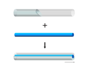
Consider a horizontal rod inside a horizontal circular capillary of outer tube radius Ro and rod radius Ri partially filled with a liquid and a gas in a downward gravity field (see figure 1). The concentric annular tube is infinitely long and has a constant cross-section with its radius ratio being defined as χ = Ri/Ro. The centroid of the concentric annulus lies on the x axis. The outer tube radius Ro is used as the characteristic length to define the Bond number of the system.

Figure 1. (a) Schematic of rod insertion into a horizontal circular capillary leading to change of a long liquid droplet from a plug to non-occlusion in a downward gravity field; (b) a cross-section of the horizontal concentric annular tube of inner and outer radii Ri and Ro with gas–liquid interface  $\varGamma$, total and liquid interiors
  $\varOmega$ and
  ${\varOmega^\ast }$, total and wetting inner perimeters
  ${\varSigma_i}$ and
  $\varSigma_i^\ast $, total and wetting outer perimeters
  ${\varSigma_o}$ and
  $\varSigma_o^\ast $ and inner and outer contact angles γi and γo.
The macroscopic free energy of a liquid drop in a capillary includes the free surface energy, the wetting energy, the gravitational energy and a liquid internal energy term that imposes a volumetric constraint on the problem. Under equilibrium conditions, the shape of the droplet is such that the total free energy is minimized.
In an infinitely long capillary, there are only two equilibrium states, that is, liquid plug and liquid non-occlusion. The effect of contact angle on the critical Bond number is normally presented in the form of a plot of critical Bond number as a function of contact angle and this plot is referred to as ‘the critical emptying line’. The liquid tongue for the state of the liquid plug is finitely long and that for the state of liquid non-occlusion is infinitely long. The tongue gets longer with larger Bond number and becomes very long when the Bond number approaches the critical Bond number, as demonstrated by the 3-D interfaces (see figure 2) directly computed via Surface Evolver (Brakke Reference Brakke1992); when the critical Bond number is attained, the tongue can be seen to be infinitely long and the cross-section intersected with the tongue can be seen to be translationally invariant. The total free energy of a 3-D droplet is finite. The total free energy per unit length of the tongue corresponding to the critical emptying line should be equal to 0. In this case, the 3-D problem can be reduced to an associated 2-D problem. The total free energy per unit length of liquid tongue based on a cross-section of an annular capillary is
 \begin{equation}\varPhi = \varGamma - (\varSigma _o^\ast \cos {\gamma _o} + \varSigma _i^\ast \cos {\gamma _i}) + l_{ca}^{ - 2}\int_{{\varOmega ^\ast }} {y\,\textrm{d}x\,\textrm{d}y} + \lambda {\varOmega ^\ast },\end{equation}
where λ is a Lagrange parameter,  $\varGamma $ is the length of the gas–liquid interface (meniscus),
  $\varSigma_o^\ast $ and
  $\varSigma_i^\ast $ are the perimeters of the tube outer and inner walls in contact with the liquid, respectively,
  ${\varOmega ^\mathrm{\ast }}$ is the liquid area and γi and γo are the inner and outer contact angles, respectively (see figure 1b). The critical emptying line can be determined when the below condition is satisfied (Finn Reference Finn1986; Manning et al. Reference Manning, Collicott and Finn2011; Rascón et al. Reference Rascón, Parry and Aarts2016):
 \begin{equation}\varPhi =\ 0.\end{equation}
Figure 2. Schematic of evolution of the 3-D interface (an oblique view) as the Bond number gradually increases and approaches the critical Bond number. The 3-D interfaces computed by Surface Evolver (Brakke Reference Brakke1992) are integrated in a horizontal concentric annular tube.
The Young--Laplace equation describing the shape of a gas–liquid interface can be determined by minimization of the total free energy of the 3-D droplet. The Young--Laplace equation in two dimensions is given by (Bhatnagar & Finn Reference Bhatnagar and Finn2016; Zhou & Zhang Reference Zhou and Zhang2017)
 \begin{equation}{\left( {\frac{{{y_x}}}{{{{(1 + y_x^2)}^{0.5}}}}} \right)_x} = l_{ca}^{ - 2}y + \lambda .\end{equation}
The Lagrange parameter λ can be obtained from integration of (2.3) as
 \begin{equation}\lambda = \frac{{{\varSigma_o}\cos {\gamma _o} + {\varSigma_i}\cos {\gamma _i}}}{\varOmega } = \frac{{2(\cos {\gamma _o} + \chi \cos {\gamma _i})}}{{{R_o}(1 - {\chi ^2})}},\end{equation}
where  $\varOmega $ is the cross-sectional area of the capillary. The numerical procedure is used as below. First, guess a value of the Bond number. The location of the three-phase contact point at the outer tube wall changes gradually from the lowest point to the highest point to calculate the gas–liquid interfaces by (2.3) with the contact angle conditions being satisfied and then obtain the value of the functional
  $\varPhi$ from (2.1). Next, modify the value of the Bond number based on the difference between the minimum value of the functional
  $\varPhi$ and zero and then recalculate. The iteration computation is repeated until (2.2) is satisfied.
When the contact angles of the inner and outer walls of a horizontal concentric annular tube are uniform  $({\gamma _o} = {\gamma _i} = \gamma )$, the Lagrange parameter λ can be reduced to
 \begin{equation}\lambda = \frac{{2\cos \gamma }}{{{R_o}(1 - \chi )}}.\end{equation}
From the above equation, it is indicated that the concentric annular tube of outer radius  ${R_o}$ and radius ratio χ has a larger value of λ than the circular tube of radius
  ${R_o}$ when the two tubes have the same contact angles.
For the uniform contact angle  ${\gamma _o} = {\gamma _i} = 90\mathrm{^\circ }$, the constant λ is equal to 0, and the interface is a straight line on the x axis. By substituting the relevant parameters into (2.2), we obtain the theoretical critical Bond number as
 \begin{equation}{Bo_c} = \frac{3}{{{{(\chi + 0.5)}^2} + 0.75}}.\end{equation}
The analytical expression for the critical Bond number given by (2.6) applies only for the case of inner and outer contact angles both equal to 90°. In the special case, the critical Bond number Boc is found to be equal to 3 for a horizontal circular capillary without an inside central rod, decreases with χ increasing and approaches the limit of 1 when  $\chi \to 1$. This indicates that rod insertion can cause liquid emptying of a horizontal capillary (see figure 1a).
3. Experimental validation
Experiments were carried out to observe whether a long water droplet is in a plug or non-occlusion state before and after a rod is inserted into a long horizontal circular capillary tube. Both the tube of 20 cm in length and the rod of 30 cm in length were made of silica glass. The silica glass had a contact angle of approximately 30°. The two ends of the tube were open and, for the concentric annular tube case, the inside rod was hung on two accessories that were manufactured by 3D printing. The fluids in capillaries were exposed to two LED light sources. A Nikon D7200 camera mounted with Nikon Micro-NIKKOR 105 mm f/2.8G macro lenses was used to visualize the fluids in capillaries.
In the experiments for circular capillaries and concentric annular capillaries of inner-to-outer radius ratio  $\chi \approx 0.5$, we used capillaries of different radii to vary the Bond number. We experimentally observe that the circular capillary is plugged by a long liquid droplet before a rod is inserted and, amazingly, the insertion of the rod leads to the emptying of the circular capillary when the Bond number is between Boc for circular capillary and Boc for concentric annular tube (χ = 0.5) (see figure 3). This observation from the experiments of several samples basically coincides with the prediction of calculations using the mathematical model as presented in § 2 (see figures 3b and 3c). The capillaries are so long that the effect of the contact angle pinning at the sharp edge is negligible here.

Figure 3. (a) Theoretical predictions for the ‘critical emptying lines’ (Boc(γ) where γo = γi = γ) for the open capillary (upper black line), and for the capillary χ = 0.5 with rod inserted (lower red line). Also shown are experimental results for a 6.79 mm diameter tube with rod inserted (P 1) and for a 5.92 mm diameter tube with rod inserted (P 2). Results are also presented for larger diameter capillaries again with inserted rods. The red circles indicate liquid non-occlusion and the red cross indicates that the liquid plug remains. Note that, as predicted by theory, the larger tube becomes non-occluding after rod insertion (see P 1) whereas the smaller tube remains blocked (see P 2). Panels (b) and (c) show photographs of the liquid plug or non-occlusion before and after rod insertion in the two cases P 1 and P 2.
4. Results and discussion
The critical Bond numbers of the concentric annular tubes of various inner-to-outer radius ratios χ ranging from 0 to 0.9 at an interval of 0.1 for the uniform contact angles  $({\gamma _o} = {\gamma _i})$ varying from 1° to 179° with an increment of 1° are shown in figure 4. The results for χ = 0 (representing a circular cylinder) are in excellent agreement with those calculated theoretically and directly computed via Surface Evolver (Brakke Reference Brakke1992) in 3-D mode, by Manning et al. (Reference Manning, Collicott and Finn2011) and Rascón et al. (Reference Rascón, Parry and Aarts2016), independently. The calculated results for different values of χ for the cases
  ${\gamma _o} = {\gamma _i} = 90\mathrm{^\circ }$ are also in good agreement with the analytical solutions by (2.6) and those directly computed via Surface Evolver in 3-D mode, which again validates the model considering the effect of the radius ratio. As shown in figure 4, the insertion of a circular tube causes the reduction of Boc for a wide range of contact angles for
  $\chi \le 0.6$ (for example, from 47° to 133° for χ = 0.1) and for all the contact angles for
  $\chi \ge 0.7$. Especially, it causes a large reduction of the maximum of Boc reached at
  ${\gamma _o} = {\gamma _i} = 90\mathrm{^\circ }$ and the reduction is more for larger radius ratio.

Figure 4. Critical Bond numbers of a horizontal circular tube (χ = 0) and a horizontal concentric annular tube versus uniform contact angle γo = γi. The radius ratio of the concentric annular cylinder changes from 0.1 to 0.9. The triangles and the crosses denote the data calculated by (2.6) and those directly computed via Surface Evolver in 3-D mode, respectively, for γo = γi = 90°. The circles denote the kinks of the curves. The squares denote the representative points each corresponding to a cross-section of the part of the interface that extends to infinite length at the critical Bond number. Here, A0, B0, C0, D0 and E0 correspond to γo = γi = 10°, 50°, 90°, 130° and 170°, respectively, for the circular cylinder, while, A, B, C, D and E correspond to γo = γi = 10°, 50°, 90°, 130° and 170°, respectively, for the concentric annular cylinder with χ = 0.1.
Figure 4 also gives the pictures, each of which represents a cross-section of the part of the interface extending to infinite length at the critical Bond number, for the circular cylinder and the concentric annular cylinder with χ = 0.1, in the representative cases of γo = γi = 10°, 50°, 90°, 130° and 170°. There exist three different non-occluded liquid topologies in a capillary with an inside concentric rod. For the type 1 topology (for example, the cross-section A), the gas–liquid interface is below the rod. For the type 3 topology (for example, the cross-section E), the interface is above the rod. The respective interfaces of the two topologies only meet the outer wall. For the type 2 topology (for example, the cross-sections B–D), the interface meets both the inner and outer walls. The interfaces for the three topologies are symmetric with respect to the vertical line of symmetry of the cross-section. This is attributed to both the uniformity of the contact angles on different linked parts of the outer wall and the uniformity of the contact angles on different linked parts of the inner rod.
For χ = 0.1 and 0.2, with the uniform contact angle increasing, the type 1, 2 and 3 topologies occur in sequence. The type 2 topology corresponds to most of the contact angels, while the type 1 topology exists for small contact angles and the type 3 topology exists for large contact angles. Each of the two transitions between the type 1 topology and the type 2 topology and between the type 2 topology and the type 3 topology is accompanied by the occurrence of a kink of the Boc curve. With the increase of χ from 0 to 0.2, the minimum of Boc attained at  ${\gamma _o} = {\gamma _i} = 1\mathrm{^\circ }$ or 179° increases. For χ = 0.3–0.9, there only exists the type 2 topology. In this case, the curves of Boc become smooth and the contact angle has a small influence on the value of Boc. With χ increasing from 0.3 to 0.9, the minimum of Boc gradually decreases, and the minimum for
  $\chi \ge 0.7$ becomes a little lower than the minimum for the circular tube. It is found that, for the cases of the uniform contact angles, the minimum critical Bond number is influenced to a small extent by changing the radius ratio of the tube.
Is it possible to further reduce the critical Bond number for a rod inside a capillary? We try to answer this question by setting different contact angles. In reality, it is easy to choose to use an inserted rod with a different contact angle from that of the capillary tube. We should examine the effect of changing the inside rod contact angle from the outer tube contact angle (which is different from the case of differing contact angles of four linked walls of the rectangle as shown in Zhu et al. Reference Zhu, Zhou and Zhang2020) on Boc. As shown in figure 4, Boc reaches the maximum at contact angles of γo = γi = 90°. By keeping γi constant (= 90°), the variations of Boc with the contact angle γo for different radius ratios are shown in figure 5. The curves are still symmetric about the vertical line γo = 90°. Compared with the circular tube, the maximum of Boc for the annular tube is reduced by an amount that increases with increasing radius ratio; however, the minimum reached at γo = 1° or 179° is larger for  $\chi \le 0.6$ and a little smaller for
  $\chi \ge 0.7$. The three topologies exist for χ = 0.1–0.3 but there is only the type 2 topology for
  $\chi \ge 0.4$. Compared with the case of equal inner and outer contact angles for a given radius ratio, the minimum of Boc is reduced by an amount that is very small for
  $\chi \ge 0.4$.

Figure 5. Critical Bond number of a horizontal concentric annular tube for inner wall contact angle γi = 90° versus outer wall contact angle γo. The radius ratio of the concentric annular cylinder changes from 0.1 to 0.8. The circles denote the kinks of the curves. The squares denote the representative points each corresponding to a cross-section of the part of the interface that extends to infinite length at the critical Bond number. Here, A, B, C, D and E correspond to γo = 10°, 50°, 90°, 130° and 170°, respectively, for χ = 0.1.
The interface for the case of γi and γo is found to be symmetrical to the interface for the case of 180°–γi and 180°–γo over the x-axis. Under these circumstances, based on (2.2), it is observed that the critical Bond number for the case of the inner wall contact angle γi and the outer wall contact angle γo is equal to that for the other case of the inner wall contact angle 180°–γi and the outer wall contact angle 180°–γo. In order to further analyse the effect of the non-uniformity of γi and γo effectively, the inner wall contact angle is changed to 60° (120°), 30° (150°), 5° (175°) and 1° (179°), all of which are smaller (larger) than 90°. The variations of Boc with the contact angle γo for different radius ratios and different inner wall contact angles are shown in figure 6. In this figure, the curves are not symmetric about the vertical line γo = 90°. As shown in figure 6(a–c), the minimum is attained at γo = 179° (1°) and χ = 0.8, and decreases with smaller (larger) value of γi. By further reducing (increasing) the inner wall contact angle to γi = 1° (179°), the minima for  $\chi \ge 0.8$ become lower than 0.13 and even the minimum for χ = 0.9 is equal to approximately 0.058 (see figure 6d). In comparison with a circular tube and even a concentric annular tube of equal inner and outer contact angles, the minima are clearly reduced and the maxima are slightly reduced.

Figure 6. Critical Bond number of a horizontal concentric annular tube for inner wall contact angles γi = (a) 60° (120°), (b) 30° (150°), (c) 5° (175°) and (d) 1° (179°) versus outer wall contact angle γo. The tick values outside the brackets on the horizontal axis correspond to the cases for γi = (a) 60°, (b) 30°, (c) 5° or (d) 1°, while those inside the brackets on the horizontal axis correspond to the cases for γi = (a) 120°, (b) 150°, (c) 175° or (d) 179°. In (a–c), different radius ratios from 0.1 to 0.8 are used and in (d) different radius ratios from 0.5 to 0.9 are used. The circles denote the kinks of the curves. The squares denote the representative points each corresponding to a cross-section of the part of the interface that extends to infinite length at the critical Bond number. Here, A, B, C, D and E on the upper (lower) row correspond to γo = 10° (170°), 50° (130°), 90° (90°), 130° (50°) and 170° (10°), respectively, for (a–c) χ = 0.1 and (d) χ = 0.9. In (a–d), the interfaces for A, B, C, D and E in the upper row are shown to be symmetrical to the interfaces for A, B, C, D and E in the lower row over the x axis, respectively.
Unlike differing contact angles of four linked walls of a horizontal rectangular tube (Zhu et al. Reference Zhu, Zhou and Zhang2020), differing inner rod contact angles from the outer tube wall contact angle in the horizontal concentric annular tube never leads to the increase of the maximum critical Bond number but only decreases the minimum. It is concluded that the insertion of a hydrophobic circular rod with a large enough radius can make liquid emptying easier in a hydrophilic circular tube. The insertion of a hydrophilic circular rod with a large enough radius can also make liquid emptying easier in a hydrophobic circular tube.
5. Conclusions
In this paper, the effect of insertion of a rod on liquid emptying of a horizontal capillary in a downward gravity field is studied. The critical Bond numbers for the concentric annular tube for the cases with uniform inner and outer wall contact angles and the cases of differing inner rod contact angles from the outer tube contact angle are analysed, and the influence of the cross-section inner-to-outer radius ratio on the critical Bond number is examined.
Compared with the cases for a circular tube, for a concentric annular tube with uniform inner and outer contact angles, the maximum of Boc reached for the inner and outer wall contact angle  ${\gamma _i} = {\gamma _o} = 90\mathrm{^\circ }$ decreases clearly, and the reduction is larger for larger radius ratio; however, the minimum is larger for a radius ratio smaller than or equal to 0.6 and a little smaller for a radius ratio larger than or equal to 0.7. An analytic formula with the radius ratio for calculation of the critical Bond number for
  ${\gamma _i} = {\gamma _o} = 90\mathrm{^\circ }$ is established. Differing inner rod contact angles from the outer tube contact angle causes the curves of Boc to be asymmetric about the vertical line
  ${\gamma _o} = 90\mathrm{^\circ }$ for
  ${\gamma _i} \neq 90\mathrm{^\circ }$. If
  ${\gamma _i}$< (>) 90°, the minimum is attained at
  ${\gamma _o} = 179\mathrm{^\circ }$ (1°) and decreases with the inner wall contact angle decreasing (increasing) and with the radius ratio increasing. The minimum attained at
  ${\gamma _i} = 1\mathrm{^\circ }$ and
  ${\gamma _o} = 179\mathrm{^\circ }$ (or
  ${\gamma _i} = 179\mathrm{^\circ }$ and
  ${\gamma _o} = 1\mathrm{^\circ }$) for a large enough radius ratio is much lower than that reached for a circular tube and a concentric annular tube of equal inner and outer contact angles. The insertion of a circular rod causes the occurrence of three topologies, including the type 2 topology with the interface meeting both the inner and outer walls and the other two topologies with the respective interfaces meeting the outer wall. A large enough radius ratio induces the type 2 topology to become the only occurring topology. The insertion of a large enough circular rod with the same wall surface property as the outer circular capillary may lead to the reduction of the minimum critical Bond number but the reduction is small. The insertion of a hydrophobic (hydrophilic) circular rod with a large enough radius can make the liquid emptying easier in a hydrophilic (hydrophobic) circular capillary. It is hoped that this paper would lay a solid foundation for design of non-occluding tubes in a transverse body force field.
Funding
This research was supported in part by the National Natural Science Foundation of China (No. 11972170).
Declaration of interests
The authors report no conflict of interest.


