


1. Introduction
Inertial migration of suspended particles was first reported in Poiseuille flow through circular cylindrical tubes (Segre & Silberberg Reference Segre and Silberberg1961). In dilute suspensions, neutrally buoyant spherical particles were observed to migrate across streamlines to an equilibrium radial position. This phenomenon is due to the effect of inertia, as in the Stokes flow regime, a spherical particle translates parallel to the flow direction, regardless of its radial position, when it is rigid and neutrally buoyant. In recent years, this inertial focusing of suspended particles has attracted considerable attention in the field of microfluidics due to its broad range of applications, such as in the separation and filtration of particles and biological cells (e.g. Di Carlo Reference Di Carlo2009). For Reynolds numbers (
 $Re$
) below approximately 100, experimental studies using microchannels with square cross-sections have shown the presence of four equilibrium positions for spherical particles centred at the faces of the channel (Di Carlo et al.
Reference Di Carlo, Irima, Tompkins and Toner2007; Bhagat, Kuntaegowdanahalli & Papautsky Reference Bhagat, Kuntaegowdanahalli and Papautsky2008; Kim & Yoo Reference Kim and Yoo2008). Here, the Reynolds number is defined as
$Re$
) below approximately 100, experimental studies using microchannels with square cross-sections have shown the presence of four equilibrium positions for spherical particles centred at the faces of the channel (Di Carlo et al.
Reference Di Carlo, Irima, Tompkins and Toner2007; Bhagat, Kuntaegowdanahalli & Papautsky Reference Bhagat, Kuntaegowdanahalli and Papautsky2008; Kim & Yoo Reference Kim and Yoo2008). Here, the Reynolds number is defined as
 $Re=UD/{\it\nu}$
, where
$Re=UD/{\it\nu}$
, where
 $U$
is the average flow velocity,
$U$
is the average flow velocity,
 $D$
is the width of the channel and
$D$
is the width of the channel and
 ${\it\nu}$
is the kinematic viscosity of the fluid. The particle scale Reynolds number can be also defined as
${\it\nu}$
is the kinematic viscosity of the fluid. The particle scale Reynolds number can be also defined as
 $Re_{p}=Re(d/D)^{2}$
, where
$Re_{p}=Re(d/D)^{2}$
, where
 $d$
denotes the diameter of suspended particles. Numerical simulations using a finite element method have supported the presence of channel face equilibrium positions for particles that are relatively large with respect to the width of the channel for
$d$
denotes the diameter of suspended particles. Numerical simulations using a finite element method have supported the presence of channel face equilibrium positions for particles that are relatively large with respect to the width of the channel for
 $10\leqslant Re\leqslant 40$
(Di Carlo et al.
Reference Di Carlo, Edd, Humphry, Stone and Toner2009), and this has been extended up to
$10\leqslant Re\leqslant 40$
(Di Carlo et al.
Reference Di Carlo, Edd, Humphry, Stone and Toner2009), and this has been extended up to
 $Re=120$
by a recent numerical study based on the force coupling method (Abbas et al.
Reference Abbas, Magaud, Gao and Geoffroy2014). The locations of these equilibrium positions have been reported to move closer to the channel wall with increasing
$Re=120$
by a recent numerical study based on the force coupling method (Abbas et al.
Reference Abbas, Magaud, Gao and Geoffroy2014). The locations of these equilibrium positions have been reported to move closer to the channel wall with increasing
 $Re$
(Di Carlo et al.
Reference Di Carlo, Edd, Humphry, Stone and Toner2009; Choi, Seo & Lee Reference Choi, Seo and Lee2011; Abbas et al.
Reference Abbas, Magaud, Gao and Geoffroy2014), which is the same trend observed for circular cylindrical flows in experiments with a much wider range of
$Re$
(Di Carlo et al.
Reference Di Carlo, Edd, Humphry, Stone and Toner2009; Choi, Seo & Lee Reference Choi, Seo and Lee2011; Abbas et al.
Reference Abbas, Magaud, Gao and Geoffroy2014), which is the same trend observed for circular cylindrical flows in experiments with a much wider range of
 $Re$
up to 1700 (Segre & Silberberg Reference Segre and Silberberg1962; Matas, Morris & Guazzelli Reference Matas, Morris and Guazzelli2004a
,Reference Matas, Morris and Guazzelli
b
) and in theoretical analyses based on the asymptotic theory valid for
$Re$
up to 1700 (Segre & Silberberg Reference Segre and Silberberg1962; Matas, Morris & Guazzelli Reference Matas, Morris and Guazzelli2004a
,Reference Matas, Morris and Guazzelli
b
) and in theoretical analyses based on the asymptotic theory valid for
 $Re_{p}\ll 1$
(Asmolov Reference Asmolov1999; Matas, Morris & Guazzelli Reference Matas, Morris and Guazzelli2009).
$Re_{p}\ll 1$
(Asmolov Reference Asmolov1999; Matas, Morris & Guazzelli Reference Matas, Morris and Guazzelli2009).
In our recent study (Miura, Itano & Sugihara-Seki Reference Miura, Itano and Sugihara-Seki2014), we performed experiments on the inertial migration of neutrally buoyant spherical particles immersed in square channel flows in
 $Re$
ranges from 100 to 1200. Observations of the particle distribution in several cross-sections of the channel indicated that four equilibrium positions at the centres of the channel faces are also present in this
$Re$
ranges from 100 to 1200. Observations of the particle distribution in several cross-sections of the channel indicated that four equilibrium positions at the centres of the channel faces are also present in this
 $Re$
range, and an additional equilibrium position appears near each channel corner for
$Re$
range, and an additional equilibrium position appears near each channel corner for
 $Re$
greater than a certain critical value,
$Re$
greater than a certain critical value,
 $Re_{c}\;({\approx}260)$
. The former equilibrium positions were termed the channel face equilibrium positions, while the latter were termed the channel corner equilibrium positions. It was shown that the channel corner equilibrium positions move away from the channel centre and the channel face equilibrium positions approach the channel centre as
$Re_{c}\;({\approx}260)$
. The former equilibrium positions were termed the channel face equilibrium positions, while the latter were termed the channel corner equilibrium positions. It was shown that the channel corner equilibrium positions move away from the channel centre and the channel face equilibrium positions approach the channel centre as
 $Re$
increases.
$Re$
increases.
Chun & Ladd (Reference Chun and Ladd2006) conducted a numerical study of the motion of spherical particles suspended in square channel flows utilizing the lattice-Boltzmann method at Reynolds numbers between 100 and 1000. Although some of their results were consistent with the experimental observations of Miura et al. (Reference Miura, Itano and Sugihara-Seki2014), there were also some striking differences between them. Chun & Ladd (Reference Chun and Ladd2006) predicted that several equilibrium positions are present, including the corner equilibrium positions, at
 $Re=100$
, while for
$Re=100$
, while for
 $Re$
larger than 500, only corner equilibrium positions exist. This is contradictory to the experimental observations of Miura et al. (Reference Miura, Itano and Sugihara-Seki2014) described above. In addition, they predicted an outward shift of the equilibrium positions toward the channel wall with increasing
$Re$
larger than 500, only corner equilibrium positions exist. This is contradictory to the experimental observations of Miura et al. (Reference Miura, Itano and Sugihara-Seki2014) described above. In addition, they predicted an outward shift of the equilibrium positions toward the channel wall with increasing
 $Re$
, although Miura et al. (Reference Miura, Itano and Sugihara-Seki2014) observed an inward shift of the channel face equilibrium positions for
$Re$
, although Miura et al. (Reference Miura, Itano and Sugihara-Seki2014) observed an inward shift of the channel face equilibrium positions for
 $Re$
larger than about 200.
$Re$
larger than about 200.
In the present study, we utilize an immersed boundary method to perform a numerical simulation of the motion of a neutrally buoyant spherical particle suspended in the square channel flows corresponding to the experiments of Miura et al. (Reference Miura, Itano and Sugihara-Seki2014). The Reynolds numbers investigated here range from 20 to 1000, which also covers experiments using microchannels. We have focused on large particles, with a diameter of about
 $1/10$
of the channel width, which is a representative size ratio for previous studies on inertial migration. The numerical simulation presented here successfully describes the experimental results for both micro scale and larger millimetre scale channel flows. For
$1/10$
of the channel width, which is a representative size ratio for previous studies on inertial migration. The numerical simulation presented here successfully describes the experimental results for both micro scale and larger millimetre scale channel flows. For
 $Re$
smaller than about 260, only channel face equilibrium positions are present, whereas for
$Re$
smaller than about 260, only channel face equilibrium positions are present, whereas for
 $Re$
beyond this value, additional equilibrium positions appear near the channel corners. An increase in
$Re$
beyond this value, additional equilibrium positions appear near the channel corners. An increase in
 $Re$
from small values is predicted to produce an outward shift of the channel face equilibrium positions in the range of
$Re$
from small values is predicted to produce an outward shift of the channel face equilibrium positions in the range of
 $Re$
for microchannel flows, followed by the inward shift in the range of
$Re$
for microchannel flows, followed by the inward shift in the range of
 $Re$
for millimetre scale channel flows. In addition, the migration behaviours of the particles in the channel cross-section are also predicted, which account for the particle distributions observed experimentally at several cross-sections downstream of the channel inlet.
$Re$
for millimetre scale channel flows. In addition, the migration behaviours of the particles in the channel cross-section are also predicted, which account for the particle distributions observed experimentally at several cross-sections downstream of the channel inlet.
2. Numerical method
We consider the motion of a single spherical particle immersed in a pressure-driven flow of an incompressible Newtonian fluid through a square channel, as shown in figure 1. The
 $x$
-axis is taken along the centreline of a square channel of width
$x$
-axis is taken along the centreline of a square channel of width
 $D$
. The channel walls are located at
$D$
. The channel walls are located at
 $y=\pm D/2$
and
$y=\pm D/2$
and
 $z=\pm D/2$
. The particle of diameter
$z=\pm D/2$
. The particle of diameter
 $d$
is assumed to be neutrally buoyant, i.e. the densities of the fluid and the particle are equal.
$d$
is assumed to be neutrally buoyant, i.e. the densities of the fluid and the particle are equal.

Figure 1. Configuration for a neutrally buoyant spherical particle of diameter
 $d$
suspended in a pressure-driven flow through a square channel of width
$d$
suspended in a pressure-driven flow through a square channel of width
 $D$
. The computational domain has length
$D$
. The computational domain has length
 $l$
in the undisturbed flow direction, at both ends of which we apply periodic boundary conditions.
$l$
in the undisturbed flow direction, at both ends of which we apply periodic boundary conditions.
The governing equations for the fluid flow are the equation of continuity and the Navier–Stokes equations. The motion of the suspended particle obeys Newton’s second law of motion. These equations are solved numerically using the immersed boundary method proposed by Kajishima et al. (Reference Kajishima, Takiguchi, Hamasaki and Miyake2001). Briefly, we introduce the average velocity of the fluid and the particle in terms of a scalar,
 ${\it\alpha}$
,
${\it\alpha}$
,
 $$\begin{eqnarray}\boldsymbol{u}=(1-{\it\alpha})\boldsymbol{u}_{f}+{\it\alpha}\boldsymbol{u}_{p},\end{eqnarray}$$
where
 $\boldsymbol{u}_{f}$
represents the fluid velocity and
$\boldsymbol{u}_{f}$
represents the fluid velocity and
 $\boldsymbol{u}_{p}$
represents the velocity inside the particle, which satisfies
$\boldsymbol{u}_{p}$
represents the velocity inside the particle, which satisfies
 $$\begin{eqnarray}\boldsymbol{u}_{p}=\boldsymbol{V}+{\it\bf\Omega}\times \boldsymbol{R}.\end{eqnarray}$$
Here,
 $\boldsymbol{V}$
is the translational velocity,
$\boldsymbol{V}$
is the translational velocity,
 ${\it\bf\Omega}$
is the angular velocity of the particle relative to the particle centre, and
${\it\bf\Omega}$
is the angular velocity of the particle relative to the particle centre, and
 $\boldsymbol{R}$
is the position vector from the particle centre. The scalar
$\boldsymbol{R}$
is the position vector from the particle centre. The scalar
 ${\it\alpha}$
represents the volume fraction of the solid phase (particle) occupying the computational cell considered;
${\it\alpha}$
represents the volume fraction of the solid phase (particle) occupying the computational cell considered;
 ${\it\alpha}=0$
in the fluid region and
${\it\alpha}=0$
in the fluid region and
 ${\it\alpha}=1$
inside the particle. Thus, the velocity
${\it\alpha}=1$
inside the particle. Thus, the velocity
 $\boldsymbol{u}$
in (2.1) represents the volume-weighted velocity average in each computational cell.
$\boldsymbol{u}$
in (2.1) represents the volume-weighted velocity average in each computational cell.
For the no-slip condition at the surface of the particle, it can be shown that the average velocity
 $\boldsymbol{u}$
satisfies the equation of continuity:
$\boldsymbol{u}$
satisfies the equation of continuity:
 $$\begin{eqnarray}\boldsymbol{{\rm\nabla}}\boldsymbol{\cdot }\boldsymbol{u}=0.\end{eqnarray}$$
Corresponding to the Navier–Stokes equations for
 $\boldsymbol{u}_{f}$
, we use the following equation for
$\boldsymbol{u}_{f}$
, we use the following equation for
 $\boldsymbol{u}$
:
$\boldsymbol{u}$
:
 $$\begin{eqnarray}{\it\rho}\left\{\frac{\partial \boldsymbol{u}}{\partial t}+(\boldsymbol{u}\boldsymbol{\cdot }\boldsymbol{{\rm\nabla}})\boldsymbol{u}\right\}=-\boldsymbol{{\rm\nabla}}p+{\it\mu}\boldsymbol{{\rm\nabla}}\boldsymbol{\cdot }[\boldsymbol{{\rm\nabla}}\boldsymbol{u}+(\boldsymbol{{\rm\nabla}}\boldsymbol{u})^{\text{T}}]+\boldsymbol{f},\end{eqnarray}$$
where
 $p$
is the pressure,
$p$
is the pressure,
 ${\it\rho}$
is the density and
${\it\rho}$
is the density and
 ${\it\mu}$
is the viscosity of the fluid. The force term on the right-hand side of equation (2.4),
${\it\mu}$
is the viscosity of the fluid. The force term on the right-hand side of equation (2.4),
 $\boldsymbol{f}$
, represents the interaction between the fluid and solid phases, and is determined such that it satisfies the condition that the velocity inside the particle coincides with the particle velocity (2.2). The value of
$\boldsymbol{f}$
, represents the interaction between the fluid and solid phases, and is determined such that it satisfies the condition that the velocity inside the particle coincides with the particle velocity (2.2). The value of
 $\boldsymbol{f}$
is evaluated at each time step in the time-marching procedure using a fractional step method (Kajishima et al.
Reference Kajishima, Takiguchi, Hamasaki and Miyake2001). For boundary conditions, we adopt the no-slip condition at the channel walls at
$\boldsymbol{f}$
is evaluated at each time step in the time-marching procedure using a fractional step method (Kajishima et al.
Reference Kajishima, Takiguchi, Hamasaki and Miyake2001). For boundary conditions, we adopt the no-slip condition at the channel walls at
 $y=\pm D/2$
and
$y=\pm D/2$
and
 $z=\pm D/2$
, and periodic conditions at the upstream and downstream ends of the channel at
$z=\pm D/2$
, and periodic conditions at the upstream and downstream ends of the channel at
 $x=0$
and
$x=0$
and
 $l$
. A constant pressure difference is also applied between both ends.
$l$
. A constant pressure difference is also applied between both ends.
As
 $\boldsymbol{f}$
represents the force exerted on the fluid by the particle,
$\boldsymbol{f}$
represents the force exerted on the fluid by the particle,
 $-\boldsymbol{f}$
acts on the particle. Thus, the motion of the particle can be determined by
$-\boldsymbol{f}$
acts on the particle. Thus, the motion of the particle can be determined by
 $$\begin{eqnarray}\frac{\text{d}(m\boldsymbol{V})}{\text{d}t}=-\int _{V}\boldsymbol{f}\,\text{d}V,\quad \frac{\text{d}(\boldsymbol{I}\boldsymbol{\cdot }{\it\bf\Omega})}{\text{d}t}=-\int _{V}\boldsymbol{r}\times \boldsymbol{f}\,\text{d}V,\end{eqnarray}$$
where
 $m$
and
$m$
and
 $\boldsymbol{I}$
represent the mass and moment of inertia of the particle, respectively. The integrations are performed over the volume of the particle.
$\boldsymbol{I}$
represent the mass and moment of inertia of the particle, respectively. The integrations are performed over the volume of the particle.
Equations (2.5) are used to calculate the trajectories of a particle that is floating freely in the flow. To calculate the lateral forces
 $F_{y}$
and
$F_{y}$
and
 $F_{z}$
exerted on the particle by the fluid flow, we assume that the suspended particle moves freely in the
$F_{z}$
exerted on the particle by the fluid flow, we assume that the suspended particle moves freely in the
 $x$
-direction and rotates freely in all directions, but does not move laterally. In this case, we use the following equations instead of equations (2.5):
$x$
-direction and rotates freely in all directions, but does not move laterally. In this case, we use the following equations instead of equations (2.5):
 $$\begin{eqnarray}\frac{\text{d}(mV_{x})}{\text{d}t}=-\int _{V}f_{x}\,\text{d}V,\quad \frac{\text{d}(\boldsymbol{I}\boldsymbol{\cdot }{\it\bf\Omega})}{\text{d}t}=-\int _{V}\boldsymbol{r}\times \boldsymbol{f}\,\text{d}V,\end{eqnarray}$$
together with the condition of
 $V_{y}=V_{z}=0$
, and calculate the lateral force
$V_{y}=V_{z}=0$
, and calculate the lateral force
 $(F_{y},F_{z})$
by
$(F_{y},F_{z})$
by
 $$\begin{eqnarray}F_{y}=-\int _{V}f_{y}\,\text{d}V,\quad F_{z}=-\int _{V}f_{z}\,\text{d}V.\end{eqnarray}$$
To determine the value of
 ${\it\alpha}$
, Kajishima et al. (Reference Kajishima, Takiguchi, Hamasaki and Miyake2001) evaluated the volume fraction of the solid phase in the computational cell by approximating the particle surface by a plane tangential to it. In the present study, we adopt for each computational cell
${\it\alpha}$
, Kajishima et al. (Reference Kajishima, Takiguchi, Hamasaki and Miyake2001) evaluated the volume fraction of the solid phase in the computational cell by approximating the particle surface by a plane tangential to it. In the present study, we adopt for each computational cell
 $$\begin{eqnarray}{\it\alpha}=\frac{1}{2}\left\{1-\tanh \frac{|\boldsymbol{R}|-d/2}{{\it\xi}}\right\},\end{eqnarray}$$
where
 $\boldsymbol{R}$
is the position vector of the centre of the computational cell relative to the particle centre and
$\boldsymbol{R}$
is the position vector of the centre of the computational cell relative to the particle centre and
 ${\it\xi}$
represents the width of the interface between the fluid and the particle, which is chosen to be comparable to the width of the computational cell,
${\it\xi}$
represents the width of the interface between the fluid and the particle, which is chosen to be comparable to the width of the computational cell,
 ${\it\Delta}$
(Nakayama & Yamamoto Reference Nakayama and Yamamoto2005).
${\it\Delta}$
(Nakayama & Yamamoto Reference Nakayama and Yamamoto2005).

Figure 2. Non-dimensional lateral forces
 $F_{y}$
(filled circles) and
$F_{y}$
(filled circles) and
 $F_{z}$
(crosses) exerted on a particle when the particle is placed on the
$F_{z}$
(crosses) exerted on a particle when the particle is placed on the
 $y$
-axis for
$y$
-axis for
 $d/D=0.22$
and
$d/D=0.22$
and
 $Re=40$
. The corresponding results for
$Re=40$
. The corresponding results for
 $F_{y}$
obtained by Di Carlo et al. (Reference Di Carlo, Edd, Humphry, Stone and Toner2009) are shown by hollow squares.
$F_{y}$
obtained by Di Carlo et al. (Reference Di Carlo, Edd, Humphry, Stone and Toner2009) are shown by hollow squares.
The numerical scheme was validated and the accuracy was assessed in two cases. In the first case, we computed the drag force acting on a stationary spherical particle in an unbounded uniform flow and compared the obtained results with the reference (Bird, Stewart & Lightfoot Reference Bird, Stewart and Lightfoot2007), in the same manner as Kajishima et al. (Reference Kajishima, Takiguchi, Hamasaki and Miyake2001) tested the numerical method in a wide range of the Reynolds number
 $Ud/{\it\nu}$
for various spacial resolutions
$Ud/{\it\nu}$
for various spacial resolutions
 ${\it\Delta}$
. Here,
${\it\Delta}$
. Here,
 $U$
represents the velocity of the uniform flow. Similar to the estimate of Kajishima et al. (Reference Kajishima, Takiguchi, Hamasaki and Miyake2001), the present simulation yielded about 8 % error in the drag force for
$U$
represents the velocity of the uniform flow. Similar to the estimate of Kajishima et al. (Reference Kajishima, Takiguchi, Hamasaki and Miyake2001), the present simulation yielded about 8 % error in the drag force for
 ${\it\Delta}/d=0.1$
and at most 5 % error for
${\it\Delta}/d=0.1$
and at most 5 % error for
 ${\it\Delta}/d=0.05$
at
${\it\Delta}/d=0.05$
at
 $Ud/{\it\nu}\leqslant 200$
, corresponding to
$Ud/{\it\nu}\leqslant 200$
, corresponding to
 $Re=UD/{\it\nu}\leqslant 1800$
for
$Re=UD/{\it\nu}\leqslant 1800$
for
 $d/D=0.11$
. In order to treat a turbulent flow of multiparticle suspensions, they adopted
$d/D=0.11$
. In order to treat a turbulent flow of multiparticle suspensions, they adopted
 ${\it\Delta}/d=0.125$
, which provided less than 10 % error in the drag force for
${\it\Delta}/d=0.125$
, which provided less than 10 % error in the drag force for
 $Ud/{\it\nu}\leqslant 400$
. In the present study, we set
$Ud/{\it\nu}\leqslant 400$
. In the present study, we set
 ${\it\Delta}/d=0.05$
.
${\it\Delta}/d=0.05$
.
In the second case, the results of the present problem were compared with previous studies for low Reynolds numbers. Di Carlo et al. (Reference Di Carlo, Edd, Humphry, Stone and Toner2009) treated a similar problem with a finite element method for a relatively large particle for
 $Re\leqslant 40$
. We performed a computation using their parameter values and compared the results, as shown in figure 2. This shows the lateral force
$Re\leqslant 40$
. We performed a computation using their parameter values and compared the results, as shown in figure 2. This shows the lateral force
 $F_{y}$
exerted on a particle placed at various positions on the
$F_{y}$
exerted on a particle placed at various positions on the
 $y$
-axis with
$y$
-axis with
 $d/D=0.22$
and
$d/D=0.22$
and
 $Re=40$
. Although fairly good agreement was obtained overall, there were some discrepancies, especially for a particle placed close to the channel walls. The relative error between the two results was about 10 % on average. One reason for these discrepancies may be that the precise results of Di Carlo et al. (Reference Di Carlo, Edd, Humphry, Stone and Toner2009) were difficult to read from figure 3 of their paper. The present computation confirmed that the lateral forces
$Re=40$
. Although fairly good agreement was obtained overall, there were some discrepancies, especially for a particle placed close to the channel walls. The relative error between the two results was about 10 % on average. One reason for these discrepancies may be that the precise results of Di Carlo et al. (Reference Di Carlo, Edd, Humphry, Stone and Toner2009) were difficult to read from figure 3 of their paper. The present computation confirmed that the lateral forces
 $F_{z}$
vanish at all positions (crosses in figure 2), as expected from symmetry considerations. The intersection of the force curve
$F_{z}$
vanish at all positions (crosses in figure 2), as expected from symmetry considerations. The intersection of the force curve
 $F_{y}$
with the horizontal axis in figure 2 indicates the location of an equilibrium position where the resultant lateral force vanishes. The channel face equilibrium positions thus obtained showed good agreement between the present results and the corresponding results in figure 3 of Di Carlo et al. (Reference Di Carlo, Edd, Humphry, Stone and Toner2009) within about 2 % error for
$F_{y}$
with the horizontal axis in figure 2 indicates the location of an equilibrium position where the resultant lateral force vanishes. The channel face equilibrium positions thus obtained showed good agreement between the present results and the corresponding results in figure 3 of Di Carlo et al. (Reference Di Carlo, Edd, Humphry, Stone and Toner2009) within about 2 % error for
 $d/D=0.22$
and
$d/D=0.22$
and
 $0.30$
at
$0.30$
at
 $Re=40$
. Further comparisons of the present results with other previous studies can be seen in figure 8(a).
$Re=40$
. Further comparisons of the present results with other previous studies can be seen in figure 8(a).
The effect of the channel length
 $l$
on the computational results was examined for various Reynolds numbers in the case of
$l$
on the computational results was examined for various Reynolds numbers in the case of
 $d/D=0.11$
. The lateral forces computed at several positions in the cross-section for
$d/D=0.11$
. The lateral forces computed at several positions in the cross-section for
 $l/d=10,20$
, and 30 were compared with the corresponding values for
$l/d=10,20$
, and 30 were compared with the corresponding values for
 $l/d=50$
. The differences between the values for
$l/d=50$
. The differences between the values for
 $l/d=10$
and 50 varied depending on the positions, but the differences between
$l/d=10$
and 50 varied depending on the positions, but the differences between
 $l/d=20$
or 30 and 50 were less than 2 % at
$l/d=20$
or 30 and 50 were less than 2 % at
 $Re=514$
and about 3 % at
$Re=514$
and about 3 % at
 $Re=968$
. In addition, the locations of the equilibrium position determined from the lateral force profiles showed a good agreement between the cases of
$Re=968$
. In addition, the locations of the equilibrium position determined from the lateral force profiles showed a good agreement between the cases of
 $l/d=20$
and 50. Thus, we adopted
$l/d=20$
and 50. Thus, we adopted
 $l/d=20$
in the present study.
$l/d=20$
in the present study.
In the experiments of Miura et al. (Reference Miura, Itano and Sugihara-Seki2014), the distributions of the particle centres were observed at downstream cross-sections of square channels of width
 $D=6.0~\text{mm}$
for neutrally buoyant spherical particles of diameter
$D=6.0~\text{mm}$
for neutrally buoyant spherical particles of diameter
 $d=0.65~\text{mm}$
. Corresponding to these experiments, we report here cases for
$d=0.65~\text{mm}$
. Corresponding to these experiments, we report here cases for
 $d/D=0.11$
. This size ratio is comparable with previous experimental and numerical studies, including Chun & Ladd (Reference Chun and Ladd2006) (
$d/D=0.11$
. This size ratio is comparable with previous experimental and numerical studies, including Chun & Ladd (Reference Chun and Ladd2006) (
 $d/D=0.11$
), Di Carlo et al. (Reference Di Carlo, Irima, Tompkins and Toner2007) (0.18), Bhagat et al. (Reference Bhagat, Kuntaegowdanahalli and Papautsky2008) (0.07–0.1), Choi et al. (Reference Choi, Seo and Lee2011) (0.075–0.16) and Abbas et al. (Reference Abbas, Magaud, Gao and Geoffroy2014) (0.11). In computing the trajectories of the particle, we adopted an undisturbed fluid velocity and half of the undisturbed vorticity vector at the centre of the particle as the initial conditions for
$d/D=0.11$
), Di Carlo et al. (Reference Di Carlo, Irima, Tompkins and Toner2007) (0.18), Bhagat et al. (Reference Bhagat, Kuntaegowdanahalli and Papautsky2008) (0.07–0.1), Choi et al. (Reference Choi, Seo and Lee2011) (0.075–0.16) and Abbas et al. (Reference Abbas, Magaud, Gao and Geoffroy2014) (0.11). In computing the trajectories of the particle, we adopted an undisturbed fluid velocity and half of the undisturbed vorticity vector at the centre of the particle as the initial conditions for
 $\boldsymbol{V}$
and
$\boldsymbol{V}$
and
 ${\it\bf\Omega}$
, respectively. The lateral forces
${\it\bf\Omega}$
, respectively. The lateral forces
 $(F_{y},F_{z})$
were estimated after the particle reached a steady state.
$(F_{y},F_{z})$
were estimated after the particle reached a steady state.

Figure 3. (a) Non-dimensional lateral force
 $F_{y}$
when the particle is placed on the
$F_{y}$
when the particle is placed on the
 $y$
-axis, and (b) non-dimensional lateral force
$y$
-axis, and (b) non-dimensional lateral force
 $F_{r}$
along the diagonal when the particle is placed on the diagonal. The variable
$F_{r}$
along the diagonal when the particle is placed on the diagonal. The variable
 $r$
represents the distance from the channel centre. The hollow squares represent the values at
$r$
represents the distance from the channel centre. The hollow squares represent the values at
 $Re=144$
and the filled circles correspond to
$Re=144$
and the filled circles correspond to
 $Re=514$
. The asterisk and the cross correspond to the experimental results at
$Re=514$
. The asterisk and the cross correspond to the experimental results at
 $Re=144$
and
$Re=144$
and
 $Re=514$
, respectively (Miura et al.
Reference Miura, Itano and Sugihara-Seki2014).
$Re=514$
, respectively (Miura et al.
Reference Miura, Itano and Sugihara-Seki2014).
3. Results and discussion
3.1. Lateral forces at low and high Reynolds numbers
As representative examples, the lateral forces exerted on a particle are plotted in figure 3(a,b) when the particle is placed on the
 $y$
-axis or on the diagonal, respectively, for
$y$
-axis or on the diagonal, respectively, for
 $Re=144$
and
$Re=144$
and
 $514$
. In figure 3(b),
$514$
. In figure 3(b),
 $r\;(=\sqrt{y^{2}+z^{2}})$
represents the distance from the channel centre and
$r\;(=\sqrt{y^{2}+z^{2}})$
represents the distance from the channel centre and
 $F_{r}$
denotes the lateral force along the diagonal. In both figures, the outward forces toward the channel walls act on the particle when it is located close to the channel centre, whereas significant wall repulsion forces act on the particle when it is placed near the channel walls. In all cases computed, one equilibrium position exists at a location between the channel centre and the channel wall, which is determined as the intersection of the force curve with the horizontal axis. The intersection on the
$F_{r}$
denotes the lateral force along the diagonal. In both figures, the outward forces toward the channel walls act on the particle when it is located close to the channel centre, whereas significant wall repulsion forces act on the particle when it is placed near the channel walls. In all cases computed, one equilibrium position exists at a location between the channel centre and the channel wall, which is determined as the intersection of the force curve with the horizontal axis. The intersection on the
 $y$
-axis, shown in figure 3(a), represents the channel face equilibrium position, and the intersection on the diagonal, shown in figure 3(b), represents the channel corner equilibrium position.
$y$
-axis, shown in figure 3(a), represents the channel face equilibrium position, and the intersection on the diagonal, shown in figure 3(b), represents the channel corner equilibrium position.
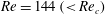
Miura et al. (Reference Miura, Itano and Sugihara-Seki2014, Reference Miura, Harada, Itano and Sugihara-Seki2015) observed the distributions of particle centres at downstream channel cross-sections, and determined the locations of equilibrium positions as local maximum positions of the probability density function of the particles. At
 $Re=144$
, the equilibrium positions thus determined are present only at the centre of the channel faces, while at
$Re=144$
, the equilibrium positions thus determined are present only at the centre of the channel faces, while at
 $Re=514$
, both the channel face and channel corner equilibrium positions are present. In figure 3(a,b), experimentally obtained equilibrium positions are indicated by an asterisk for
$Re=514$
, both the channel face and channel corner equilibrium positions are present. In figure 3(a,b), experimentally obtained equilibrium positions are indicated by an asterisk for
 $Re=144$
and a cross for
$Re=144$
and a cross for
 $Re=514$
, respectively. The locations of these equilibrium positions showed excellent agreement with the present numerical results, although there are some deviations in the experimental measurements (see figure 8
a,b). At
$Re=514$
, respectively. The locations of these equilibrium positions showed excellent agreement with the present numerical results, although there are some deviations in the experimental measurements (see figure 8
a,b). At
 $Re=144$
, the present numerical simulation predicts the presence of channel corner equilibrium positions, whereas they are not observed experimentally. We think that the channel corner equilibrium positions are unstable for
$Re=144$
, the present numerical simulation predicts the presence of channel corner equilibrium positions, whereas they are not observed experimentally. We think that the channel corner equilibrium positions are unstable for
 $Re$
smaller than a certain critical value,
$Re$
smaller than a certain critical value,
 $Re_{c}$
, and so they cannot be observed experimentally for
$Re_{c}$
, and so they cannot be observed experimentally for
 $Re<Re_{c}$
. This is discussed below.
$Re<Re_{c}$
. This is discussed below.

Figure 4. (a) Map of the lateral forces
 $(F_{y},F_{z})$
and trajectories of the particle centre projected over the channel cross-section at
$(F_{y},F_{z})$
and trajectories of the particle centre projected over the channel cross-section at
 $Re=144$
. Each arrow at the lattice represents the direction of the lateral force, and its magnitude is indicated by the colour. The triangle represents the channel face equilibrium position, which is stable, and the square shows the channel corner equilibrium position, which is unstable. The thick red line represents the heteroclinic orbit that joins the channel face equilibrium position and the corner equilibrium position. (b) Particle distribution obtained experimentally at
$Re=144$
. Each arrow at the lattice represents the direction of the lateral force, and its magnitude is indicated by the colour. The triangle represents the channel face equilibrium position, which is stable, and the square shows the channel corner equilibrium position, which is unstable. The thick red line represents the heteroclinic orbit that joins the channel face equilibrium position and the corner equilibrium position. (b) Particle distribution obtained experimentally at
 $Re=144$
. (Miura et al.
Reference Miura, Itano and Sugihara-Seki2014) and the heteroclinic orbit obtained numerically. Each dot represents the location of a particle centre observed in the cross-section.
$Re=144$
. (Miura et al.
Reference Miura, Itano and Sugihara-Seki2014) and the heteroclinic orbit obtained numerically. Each dot represents the location of a particle centre observed in the cross-section.
Figure 4(a,b) show a map of the lateral forces
 $(F_{y},F_{z})$
in the first quadrant of the channel cross-section at
$(F_{y},F_{z})$
in the first quadrant of the channel cross-section at
 $Re=144\;({<}Re_{c})$
, and the corresponding experimental particle distribution results (Miura et al.
Reference Miura, Itano and Sugihara-Seki2014). In figure 4(a), each arrow represents the direction of the lateral force acting on a particle located at the origin of the arrow, with the magnitude expressed by the colour. Several representative trajectories of the particle centre projected over the cross-section are also plotted with black lines. In figure 4(b), each dot represents the location of a particle centre observed in the cross-section; the data are summed over the region of the azimuthal angle between
$Re=144\;({<}Re_{c})$
, and the corresponding experimental particle distribution results (Miura et al.
Reference Miura, Itano and Sugihara-Seki2014). In figure 4(a), each arrow represents the direction of the lateral force acting on a particle located at the origin of the arrow, with the magnitude expressed by the colour. Several representative trajectories of the particle centre projected over the cross-section are also plotted with black lines. In figure 4(b), each dot represents the location of a particle centre observed in the cross-section; the data are summed over the region of the azimuthal angle between
 $0$
and
$0$
and
 ${\rm\pi}/4$
based on symmetry considerations.
${\rm\pi}/4$
based on symmetry considerations.
In figure 4(a), the red square represents the channel corner equilibrium position on the diagonal, the location of which is determined from the force curve shown in figure 3(b). Trajectories starting from the neighbourhood of the corner equilibrium position lead away from this location, indicating that the corner equilibrium position is unstable. In addition, trajectories starting from various initial positions approach the channel face equilibrium position (red triangle in figure 4 a), indicating that the channel face equilibrium position is stable. This is the reason why no particles are observed near the channel corners and most particles are placed near the centre of the channel face in figure 4(b).
From the trajectories illustrated in figure 4(a), we notice that the particles migrate in two stages. In the first stage, they move in nearly radial directions until they reach a single line that represents a heteroclinic orbit joining the channel face equilibrium position and the corner equilibrium position (red line in figure 4 a). In the second stage, the particles travel along the heteroclinic orbit toward the channel face equilibrium position. In accordance with this prediction, figure 4(b) shows that the particles observed experimentally are almost aligned along the heteroclinic orbit, with most particles focused near the channel face equilibrium position. The first stage is a relatively fast process, while the second stage is slower. We will show in § 3.3 that the time scale, or the travelling distance in the flow direction during each stage, depends on not only the particle position but also the Reynolds number.
The present results shown in figure 4(a) at
 $Re=144$
are consistent with previous studies for microchannel flows for
$Re=144$
are consistent with previous studies for microchannel flows for
 $1\leqslant Re\leqslant 120$
. For the same size ratio with the present study (
$1\leqslant Re\leqslant 120$
. For the same size ratio with the present study (
 $d/D=0.11$
), Abbas et al. (Reference Abbas, Magaud, Gao and Geoffroy2014) made microscope measurements of particles suspended in square microchannel flows and numerical analyses of the trajectories of a single particle based on the force coupling method. The trajectories at
$d/D=0.11$
), Abbas et al. (Reference Abbas, Magaud, Gao and Geoffroy2014) made microscope measurements of particles suspended in square microchannel flows and numerical analyses of the trajectories of a single particle based on the force coupling method. The trajectories at
 $Re=120$
shown in figure 8 of their paper are comparable to those shown in figure 4(a), although the locations of the channel face equilibrium positions obtained in the present study are closer to their experimental results rather than their numerical results (see our figure 8
a).
$Re=120$
shown in figure 8 of their paper are comparable to those shown in figure 4(a), although the locations of the channel face equilibrium positions obtained in the present study are closer to their experimental results rather than their numerical results (see our figure 8
a).
At lower
 $Re\;(=40)$
and for larger particles
$Re\;(=40)$
and for larger particles
 $(d/D=0.22)$
, the distribution of the lateral forces in the cross-section was calculated by a finite element computation (Di Carlo et al.
Reference Di Carlo, Edd, Humphry, Stone and Toner2009) and by a perturbation analysis (Hood, Lee & Roper Reference Hood, Lee and Roper2015). While not shown here, we have also plotted the map of the lateral forces and computed the trajectories for
$(d/D=0.22)$
, the distribution of the lateral forces in the cross-section was calculated by a finite element computation (Di Carlo et al.
Reference Di Carlo, Edd, Humphry, Stone and Toner2009) and by a perturbation analysis (Hood, Lee & Roper Reference Hood, Lee and Roper2015). While not shown here, we have also plotted the map of the lateral forces and computed the trajectories for
 $Re=50$
and
$Re=50$
and
 $d/D=0.11$
(Nakagawa et al.
Reference Nakagawa, Miura, Otamo, Makino and Sugihara-Seki2014), which were found to have similar features to figure 4(a); outward forces are exerted on the particle in the inner region of the heteroclinic orbit, whereas in the outer region significant repulsion forces act, with the magnitude being larger nearer to the centre of the channel face and weaker nearer to the corner. There is also a stable equilibrium position at the centre of each channel face, and an unstable equilibrium position at each corner. These features are also observed in figure 1 of Di Carlo et al. (Reference Di Carlo, Edd, Humphry, Stone and Toner2009), despite the difference in size ratio
$d/D=0.11$
(Nakagawa et al.
Reference Nakagawa, Miura, Otamo, Makino and Sugihara-Seki2014), which were found to have similar features to figure 4(a); outward forces are exerted on the particle in the inner region of the heteroclinic orbit, whereas in the outer region significant repulsion forces act, with the magnitude being larger nearer to the centre of the channel face and weaker nearer to the corner. There is also a stable equilibrium position at the centre of each channel face, and an unstable equilibrium position at each corner. These features are also observed in figure 1 of Di Carlo et al. (Reference Di Carlo, Edd, Humphry, Stone and Toner2009), despite the difference in size ratio
 $d/D$
. Hood et al. (Reference Hood, Lee and Roper2015) estimated the lateral forces using a regular perturbation method from the Stokes flow regime. Although the trajectories and the lateral force distribution shown in figure 8 of their paper are qualitatively similar to the present results, there seem some discrepancies in the region near the channel wall and around the channel corner equilibrium positions; the lateral forces in that region are rather weak compared to Di Carlo et al. (Reference Di Carlo, Edd, Humphry, Stone and Toner2009) and the present study. Large repulsion forces on the particles near the channel wall were reported experimentally by Choi et al. (Reference Choi, Seo and Lee2011) in the range of
$d/D$
. Hood et al. (Reference Hood, Lee and Roper2015) estimated the lateral forces using a regular perturbation method from the Stokes flow regime. Although the trajectories and the lateral force distribution shown in figure 8 of their paper are qualitatively similar to the present results, there seem some discrepancies in the region near the channel wall and around the channel corner equilibrium positions; the lateral forces in that region are rather weak compared to Di Carlo et al. (Reference Di Carlo, Edd, Humphry, Stone and Toner2009) and the present study. Large repulsion forces on the particles near the channel wall were reported experimentally by Choi et al. (Reference Choi, Seo and Lee2011) in the range of
 $2.4\leqslant Re\leqslant 60$
. Since the effect of the channel wall was calculated by the method of reflections in Hood et al. (Reference Hood, Lee and Roper2015), a finite number of reflections may lead to the rather weak repulsion force when a large particle is placed close to the channel wall.
$2.4\leqslant Re\leqslant 60$
. Since the effect of the channel wall was calculated by the method of reflections in Hood et al. (Reference Hood, Lee and Roper2015), a finite number of reflections may lead to the rather weak repulsion force when a large particle is placed close to the channel wall.

Figure 5. (a) Map of the lateral forces
 $(F_{y},F_{z})$
and trajectories of the particle centre projected over the channel cross-section at
$(F_{y},F_{z})$
and trajectories of the particle centre projected over the channel cross-section at
 $Re=514$
. At this
$Re=514$
. At this
 $Re$
, both the channel face equilibrium position (triangle) and the channel corner equilibrium position (square) are stable. The thick red solid line represents the heteroclinic orbit and the thick red dashed line represents the separatrix. (b) Particle distribution obtained experimentally at
$Re$
, both the channel face equilibrium position (triangle) and the channel corner equilibrium position (square) are stable. The thick red solid line represents the heteroclinic orbit and the thick red dashed line represents the separatrix. (b) Particle distribution obtained experimentally at
 $Re=514$
(Miura et al.
Reference Miura, Harada, Itano and Sugihara-Seki2015) and the heteroclinic orbit obtained numerically. For additional explanation, see figure 4.
$Re=514$
(Miura et al.
Reference Miura, Harada, Itano and Sugihara-Seki2015) and the heteroclinic orbit obtained numerically. For additional explanation, see figure 4.
The map of the lateral forces computed at
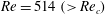 $Re=514\;({>}Re_{c})$
and the corresponding experimental results of the particle distribution (Miura et al.
Reference Miura, Harada, Itano and Sugihara-Seki2015) are shown in figure 5(a,b), respectively. Several trajectories of the particle centre are plotted with black lines in figure 5(a). The trajectories indicate that at this Reynolds number, both the channel face and channel corner equilibrium positions are stable, and separatrix (red dashed line) as well as a heteroclinic orbit (red solid line) appear in figure 5(a). The intersection of these two lines represents a saddle point. The trajectories in figure 5(a) also suggest a two stage migration of the particles: migration up to the heteroclinic orbit in the first stage and migration along the heteroclinic orbit toward either the channel face or corner equilibrium position in the second stage. This property is exemplified in figure 5(b), which shows the alignments of particles along the heteroclinic orbit near the channel face and channel corner equilibrium positions.
$Re=514\;({>}Re_{c})$
and the corresponding experimental results of the particle distribution (Miura et al.
Reference Miura, Harada, Itano and Sugihara-Seki2015) are shown in figure 5(a,b), respectively. Several trajectories of the particle centre are plotted with black lines in figure 5(a). The trajectories indicate that at this Reynolds number, both the channel face and channel corner equilibrium positions are stable, and separatrix (red dashed line) as well as a heteroclinic orbit (red solid line) appear in figure 5(a). The intersection of these two lines represents a saddle point. The trajectories in figure 5(a) also suggest a two stage migration of the particles: migration up to the heteroclinic orbit in the first stage and migration along the heteroclinic orbit toward either the channel face or corner equilibrium position in the second stage. This property is exemplified in figure 5(b), which shows the alignments of particles along the heteroclinic orbit near the channel face and channel corner equilibrium positions.
To the authors’ knowledge, there are no comparable studies investigating the lateral forces on a particle suspended in square channel flows at this
 $Re$
, except Chun & Ladd (Reference Chun and Ladd2006). They reported from their numerical simulation, using the lattice Boltzmann method, that only the channel corner equilibrium positions are stable and the channel face equilibrium positions are unstable above
$Re$
, except Chun & Ladd (Reference Chun and Ladd2006). They reported from their numerical simulation, using the lattice Boltzmann method, that only the channel corner equilibrium positions are stable and the channel face equilibrium positions are unstable above
 $Re=500$
. This result does not match our experiments (Miura et al.
Reference Miura, Itano and Sugihara-Seki2014, Reference Miura, Harada, Itano and Sugihara-Seki2015) and the present numerical simulation shown in figure 5(a). For low
$Re=500$
. This result does not match our experiments (Miura et al.
Reference Miura, Itano and Sugihara-Seki2014, Reference Miura, Harada, Itano and Sugihara-Seki2015) and the present numerical simulation shown in figure 5(a). For low
 $Re\;({\approx}100)$
, Chun & Ladd (Reference Chun and Ladd2006) found stable equilibrium positions in corners and faces while in the following numerical studies (Di Carlo et al.
Reference Di Carlo, Edd, Humphry, Stone and Toner2009; Abbas et al.
Reference Abbas, Magaud, Gao and Geoffroy2014), including the present study, and in experimental studies (Kim & Yoo Reference Kim and Yoo2008; Di Carlo et al.
Reference Di Carlo, Edd, Humphry, Stone and Toner2009; Choi et al.
Reference Choi, Seo and Lee2011; Abbas et al.
Reference Abbas, Magaud, Gao and Geoffroy2014; Miura et al.
Reference Miura, Itano and Sugihara-Seki2014), the corner corner equilibrium positions were indicated to be unstable. With regard to the discrepancy at low
$Re\;({\approx}100)$
, Chun & Ladd (Reference Chun and Ladd2006) found stable equilibrium positions in corners and faces while in the following numerical studies (Di Carlo et al.
Reference Di Carlo, Edd, Humphry, Stone and Toner2009; Abbas et al.
Reference Abbas, Magaud, Gao and Geoffroy2014), including the present study, and in experimental studies (Kim & Yoo Reference Kim and Yoo2008; Di Carlo et al.
Reference Di Carlo, Edd, Humphry, Stone and Toner2009; Choi et al.
Reference Choi, Seo and Lee2011; Abbas et al.
Reference Abbas, Magaud, Gao and Geoffroy2014; Miura et al.
Reference Miura, Itano and Sugihara-Seki2014), the corner corner equilibrium positions were indicated to be unstable. With regard to the discrepancy at low
 $Re\;({\approx}100)$
, Abbas et al. (Reference Abbas, Magaud, Gao and Geoffroy2014) reported from their numerical simulations, adopting a very short computational domain, that the particle can be pushed towards the channel corner instead of the centre of the channel face at
$Re\;({\approx}100)$
, Abbas et al. (Reference Abbas, Magaud, Gao and Geoffroy2014) reported from their numerical simulations, adopting a very short computational domain, that the particle can be pushed towards the channel corner instead of the centre of the channel face at
 $Re=120$
, suggesting that the inter-particle interaction in the flow direction may result in the presence of the channel corner equilibrium position at low
$Re=120$
, suggesting that the inter-particle interaction in the flow direction may result in the presence of the channel corner equilibrium position at low
 $Re$
. Chun & Ladd (Reference Chun and Ladd2006) employed a periodic channel length of
$Re$
. Chun & Ladd (Reference Chun and Ladd2006) employed a periodic channel length of
 $l/d=5$
for their simulations at
$l/d=5$
for their simulations at
 $Re=100{-}1000$
. Thus, the discrepancy observed at high
$Re=100{-}1000$
. Thus, the discrepancy observed at high
 $Re\;({\approx}500)$
may also originate from the hydrodynamic interaction between particles, since the wake of a particle could be larger and longer as
$Re\;({\approx}500)$
may also originate from the hydrodynamic interaction between particles, since the wake of a particle could be larger and longer as
 $Re$
increases. We will examine the effect of the channel length on the particle behaviour at high
$Re$
increases. We will examine the effect of the channel length on the particle behaviour at high
 $Re$
in a future study.
$Re$
in a future study.

Figure 6. (a) Map of the lateral forces
 $(F_{y},F_{z})$
and trajectories of the particle centre projected over the channel cross-section at
$(F_{y},F_{z})$
and trajectories of the particle centre projected over the channel cross-section at
 $Re=260$
. At this
$Re=260$
. At this
 $Re$
, an additional stable equilibrium position (red circle) appears on the heteroclinic orbit (thick red solid line). (b) Particle distributions obtained experimentally at
$Re$
, an additional stable equilibrium position (red circle) appears on the heteroclinic orbit (thick red solid line). (b) Particle distributions obtained experimentally at
 $Re=260$
(Miura et al.
Reference Miura, Itano and Sugihara-Seki2014) and the heteroclinic orbit obtained numerically. For additional explanation, see figure 4.
$Re=260$
(Miura et al.
Reference Miura, Itano and Sugihara-Seki2014) and the heteroclinic orbit obtained numerically. For additional explanation, see figure 4.
3.2. Lateral forces near the critical Reynolds number
The present numerical study showed that both the channel face and channel corner equilibrium positions always exist in the range of
 $Re$
computed, but in fact the channel corner equilibrium positions are unstable until the Reynolds number exceeds a certain critical value,
$Re$
computed, but in fact the channel corner equilibrium positions are unstable until the Reynolds number exceeds a certain critical value,
 $Re_{c}\;({\approx}260)$
. Figure 6(a,b) show a map of the lateral forces computed at
$Re_{c}\;({\approx}260)$
. Figure 6(a,b) show a map of the lateral forces computed at
 $Re=260$
and the corresponding experimental particle distribution (Miura et al.
Reference Miura, Itano and Sugihara-Seki2014), respectively. Near this
$Re=260$
and the corresponding experimental particle distribution (Miura et al.
Reference Miura, Itano and Sugihara-Seki2014), respectively. Near this
 $Re$
, it was shown experimentally that additional equilibrium positions appear at azimuthal angles of
$Re$
, it was shown experimentally that additional equilibrium positions appear at azimuthal angles of
 ${\sim}0.5{-}0.7$
rad, as well as the channel face equilibrium positions (Miura et al.
Reference Miura, Itano and Sugihara-Seki2014, Reference Miura, Harada, Itano and Sugihara-Seki2015). Corresponding to this observation, the present computation showed the presence of another stable equilibrium position on the heteroclinic orbit at
${\sim}0.5{-}0.7$
rad, as well as the channel face equilibrium positions (Miura et al.
Reference Miura, Itano and Sugihara-Seki2014, Reference Miura, Harada, Itano and Sugihara-Seki2015). Corresponding to this observation, the present computation showed the presence of another stable equilibrium position on the heteroclinic orbit at
 $Re=260$
, which is indicated by a red circle in figure 6(a). This location, of azimuthal angle
$Re=260$
, which is indicated by a red circle in figure 6(a). This location, of azimuthal angle
 $0.59$
rad, is close to the equilibrium position observed experimentally. One of the characteristics at this
$0.59$
rad, is close to the equilibrium position observed experimentally. One of the characteristics at this
 $Re$
is that the magnitudes of the lateral forces are very small along the heteroclinic orbit. This property may be demonstrated in figure 6(a), in which the trajectories (black lines) enter the heteroclinic orbit (red line) at almost right angles. The particles in the second stage move very slowly along the heteroclinic orbit, taking a long time to reach the stable equilibrium position (see figure 7). The magnitudes of the lateral forces are so small that other equilibrium positions may be present on the orbit. The slow movement in the second stage may be reflected in the experimental observation that the particles shown in figure 6(b) are aligned along almost entire circumference of the heteroclinic orbit and the focusing near the equilibrium positions is weak.
$Re$
is that the magnitudes of the lateral forces are very small along the heteroclinic orbit. This property may be demonstrated in figure 6(a), in which the trajectories (black lines) enter the heteroclinic orbit (red line) at almost right angles. The particles in the second stage move very slowly along the heteroclinic orbit, taking a long time to reach the stable equilibrium position (see figure 7). The magnitudes of the lateral forces are so small that other equilibrium positions may be present on the orbit. The slow movement in the second stage may be reflected in the experimental observation that the particles shown in figure 6(b) are aligned along almost entire circumference of the heteroclinic orbit and the focusing near the equilibrium positions is weak.
In order to examine the stability of the channel corner equilibrium position from the lateral force profile, we computed the azimuthal component of the lateral force,
 $F_{{\it\theta}}$
, along a short circular arc passing the corner equilibrium position at
$F_{{\it\theta}}$
, along a short circular arc passing the corner equilibrium position at
 $Re=144$
, 260 and 514. The computations in the range of
$Re=144$
, 260 and 514. The computations in the range of
 ${\it\theta}$
from
${\it\theta}$
from
 ${\rm\pi}/4$
to
${\rm\pi}/4$
to
 ${\rm\pi}/4-0.025$
rad indicated that, as
${\rm\pi}/4-0.025$
rad indicated that, as
 ${\it\theta}$
decreases from
${\it\theta}$
decreases from
 ${\rm\pi}/4$
,
${\rm\pi}/4$
,
 $F_{{\it\theta}}$
decreases monotonically from zero at
$F_{{\it\theta}}$
decreases monotonically from zero at
 $Re=144$
, whereas
$Re=144$
, whereas
 $F_{{\it\theta}}$
increases monotonically from zero at
$F_{{\it\theta}}$
increases monotonically from zero at
 $Re=514$
. Since the radial component of the lateral force,
$Re=514$
. Since the radial component of the lateral force,
 $F_{r}$
, vanishes at the corner equilibrium position, varying from positive to negative values with
$F_{r}$
, vanishes at the corner equilibrium position, varying from positive to negative values with
 $r$
along the diagonal, this result implies that the corner equilibrium position is a saddle point at
$r$
along the diagonal, this result implies that the corner equilibrium position is a saddle point at
 $Re=144$
and it is a stable equilibrium point at
$Re=144$
and it is a stable equilibrium point at
 $Re=514$
. The magnitudes of
$Re=514$
. The magnitudes of
 $F_{{\it\theta}}/{\it\rho}U^{2}d^{2}$
at
$F_{{\it\theta}}/{\it\rho}U^{2}d^{2}$
at
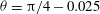 ${\it\theta}={\rm\pi}/4-0.025$
rad are about
${\it\theta}={\rm\pi}/4-0.025$
rad are about
 $2\times 10^{-4}$
at
$2\times 10^{-4}$
at
 $Re=144$
and 514. On the other hand, at
$Re=144$
and 514. On the other hand, at
 $Re=260$
the maximum value of
$Re=260$
the maximum value of
 $F_{{\it\theta}}/{\it\rho}U^{2}d^{2}$
in this range of
$F_{{\it\theta}}/{\it\rho}U^{2}d^{2}$
in this range of
 ${\it\theta}$
is about one-tenth of this value, i.e.
${\it\theta}$
is about one-tenth of this value, i.e.
 $F_{{\it\theta}}$
is extremely small, indicating that this Reynolds number is close to the critical value,
$F_{{\it\theta}}$
is extremely small, indicating that this Reynolds number is close to the critical value,
 $Re_{c}$
. The similar computations at
$Re_{c}$
. The similar computations at
 $Re=300$
also yielded small values of
$Re=300$
also yielded small values of
 $F_{{\it\theta}}$
in the same range of
$F_{{\it\theta}}$
in the same range of
 ${\it\theta}$
. As such subtle variations in the lateral forces may be beyond the accuracy of the current numerical method, further analyses of higher precision are necessary to determine the critical Reynolds number.
${\it\theta}$
. As such subtle variations in the lateral forces may be beyond the accuracy of the current numerical method, further analyses of higher precision are necessary to determine the critical Reynolds number.

Figure 7. Particle trajectories in (a) the
 $(x,y)$
plane and (b) the
$(x,y)$
plane and (b) the
 $(x,z)$
plane, starting from
$(x,z)$
plane, starting from
 $(y/(D/2),z/(D/2))=(0.5,0.375)$
, at
$(y/(D/2),z/(D/2))=(0.5,0.375)$
, at
 $Re=144$
(solid line), 260 (dashed line) and 514 (dash-dotted line). The horizontal dotted lines denote the asymptotic coordinates the trajectories approach. The dashed thin lines represent the trajectories, starting from
$Re=144$
(solid line), 260 (dashed line) and 514 (dash-dotted line). The horizontal dotted lines denote the asymptotic coordinates the trajectories approach. The dashed thin lines represent the trajectories, starting from
 $(y/(D/2),z/(D/2))=(0.2,0.1)$
, at
$(y/(D/2),z/(D/2))=(0.2,0.1)$
, at
 $Re=260$
. Note that the
$Re=260$
. Note that the
 $x$
-scale for this case is shown on the upper horizontal axis.
$x$
-scale for this case is shown on the upper horizontal axis.
3.3. Entry length for focusing
The trajectories shown in figures 4(a)–6(a) clearly demonstrate the two stage properties of the particle migration. As a representative example of the particle behaviour at each
 $Re$
, the projections of the trajectories onto the
$Re$
, the projections of the trajectories onto the
 $(x,y)$
and
$(x,y)$
and
 $(x,z)$
planes, starting from
$(x,z)$
planes, starting from
 $(y/(D/2),z/(D/2))=(0.5,0.375)$
in the cross-section, are plotted at
$(y/(D/2),z/(D/2))=(0.5,0.375)$
in the cross-section, are plotted at
 $Re=144,260$
and 514 in figure 7. The horizontal dotted lines represent the coordinates of the asymptotic position where the trajectory approaches: the channel face equilibrium position at
$Re=144,260$
and 514 in figure 7. The horizontal dotted lines represent the coordinates of the asymptotic position where the trajectory approaches: the channel face equilibrium position at
 $Re=144$
(triangle in figure 4
a), the stable equilibrium position on the heteroclinic orbit at
$Re=144$
(triangle in figure 4
a), the stable equilibrium position on the heteroclinic orbit at
 $Re=260$
(circle in figure 6
a) and the channel corner equilibrium position at
$Re=260$
(circle in figure 6
a) and the channel corner equilibrium position at
 $Re=514$
(square in figure 5
a). The first stage continues until the particle reaches the heteroclinic orbit. The travelling distance in the flow direction during the first stage can be estimated from figure 7 as
$Re=514$
(square in figure 5
a). The first stage continues until the particle reaches the heteroclinic orbit. The travelling distance in the flow direction during the first stage can be estimated from figure 7 as
 $L_{1}/D\approx 50,35$
and 30 at
$L_{1}/D\approx 50,35$
and 30 at
 $Re=144,260$
and 514, respectively. The value of
$Re=144,260$
and 514, respectively. The value of
 $L_{1}/D\approx 50$
at
$L_{1}/D\approx 50$
at
 $Re=144$
agrees with the result for
$Re=144$
agrees with the result for
 $Re=120$
reported by a numerical simulation of Abbas et al. (Reference Abbas, Magaud, Gao and Geoffroy2014), although the initial position of the trajectory is different.
$Re=120$
reported by a numerical simulation of Abbas et al. (Reference Abbas, Magaud, Gao and Geoffroy2014), although the initial position of the trajectory is different.
After the first stage, the particle translates much slower along the heteroclinic orbit towards the stable equilibrium position in the second stage. Figure 7 shows that the second stage continues until the travelling distance
 $L_{2}/D\approx 600$
and 100 from the channel inlet, at
$L_{2}/D\approx 600$
and 100 from the channel inlet, at
 $Re=144$
and 514, respectively, indicating that
$Re=144$
and 514, respectively, indicating that
 $L_{2}$
is about ten times and several times larger than
$L_{2}$
is about ten times and several times larger than
 $L_{1}$
at
$L_{1}$
at
 $Re=144$
and 514, respectively. These values of
$Re=144$
and 514, respectively. These values of
 $L_{2}$
were estimated from the axial distance where the centre of particle approaches within
$L_{2}$
were estimated from the axial distance where the centre of particle approaches within
 $0.005\times (D/2)$
to the asymptotic position. The value of
$0.005\times (D/2)$
to the asymptotic position. The value of
 $L_{2}/D\approx 600$
at
$L_{2}/D\approx 600$
at
 $Re=144$
is about a half of the result of Abbas et al. (Reference Abbas, Magaud, Gao and Geoffroy2014) for
$Re=144$
is about a half of the result of Abbas et al. (Reference Abbas, Magaud, Gao and Geoffroy2014) for
 $Re=120$
, which is presumably due to the difference in the initial position as well as the Reynolds number, or the method of estimate for
$Re=120$
, which is presumably due to the difference in the initial position as well as the Reynolds number, or the method of estimate for
 $L_{2}$
. They reported that
$L_{2}$
. They reported that
 $L_{2}/D\approx 1000$
at both
$L_{2}/D\approx 1000$
at both
 $Re=60$
and
$Re=60$
and
 $120$
, and figure 9 of their paper showed that, at
$120$
, and figure 9 of their paper showed that, at
 $Re=12$
, the particle did not approach within a close distance to the asymptotic position even at
$Re=12$
, the particle did not approach within a close distance to the asymptotic position even at
 $x/D=3000$
, indicating that
$x/D=3000$
, indicating that
 $L_{2}/D>3000$
at
$L_{2}/D>3000$
at
 $Re=12$
. The present study indicated that the axial distance of the second stage is, in general, longer for smaller
$Re=12$
. The present study indicated that the axial distance of the second stage is, in general, longer for smaller
 $Re$
, which seems consistent with the results of Abbas et al. (Reference Abbas, Magaud, Gao and Geoffroy2014).
$Re$
, which seems consistent with the results of Abbas et al. (Reference Abbas, Magaud, Gao and Geoffroy2014).
Near the critical Reynolds number, however, the lateral velocity of the particle moving along the heteroclinic orbit is so small that the particle keeps migrating in much longer axial distance in the second stage, as seen from the curve for
 $Re=260$
in figure 7. As another example for this Reynolds number, a trajectory starting from
$Re=260$
in figure 7. As another example for this Reynolds number, a trajectory starting from
 $(y/(D/2),z/(D/2))=(0.2,0.1)$
is also plotted by thin dashed lines in figure 7(a,b). Note that the horizontal axis for these curves is shrunk by one-third (the scale is shown on the upper axis). In this case also, the particle approaches asymptotically the stable equilibrium position on the heteroclinic orbit (circle in figure 6
a). The travelling distance before reaching the stable equilibrium position is estimated to be
$(y/(D/2),z/(D/2))=(0.2,0.1)$
is also plotted by thin dashed lines in figure 7(a,b). Note that the horizontal axis for these curves is shrunk by one-third (the scale is shown on the upper axis). In this case also, the particle approaches asymptotically the stable equilibrium position on the heteroclinic orbit (circle in figure 6
a). The travelling distance before reaching the stable equilibrium position is estimated to be
 $L_{2}/D\approx 1100$
from figure 7. Thus, it is demonstrated that, at
$L_{2}/D\approx 1100$
from figure 7. Thus, it is demonstrated that, at
 $Re\approx Re_{c}$
,
$Re\approx Re_{c}$
,
 $L_{2}$
is much larger than
$L_{2}$
is much larger than
 $L_{1}$
, possibly by two orders of magnitude. Therefore, we conclude from the present results that an increase in
$L_{1}$
, possibly by two orders of magnitude. Therefore, we conclude from the present results that an increase in
 $Re$
decreases
$Re$
decreases
 $L_{1}$
and it also decreases
$L_{1}$
and it also decreases
 $L_{2}$
in general, but for
$L_{2}$
in general, but for
 $Re\approx Re_{c}$
,
$Re\approx Re_{c}$
,
 $L_{2}$
could be extremely large compared to
$L_{2}$
could be extremely large compared to
 $L_{1}$
.
$L_{1}$
.
In Miura et al. (Reference Miura, Itano and Sugihara-Seki2014), we have discussed the entry length after which lateral migration has fully developed. Assuming that the lateral force is balanced by a viscous Stokes drag, we derived the conventional expression of the entry length
 $L_{e}$
as
$L_{e}$
as
 $L_{e}/l^{\prime }\approx 6{\rm\pi}A^{-1}Re^{-1}(d/D)^{-3}$
(Matas et al.
Reference Matas, Morris and Guazzelli2004a
; Di Carlo et al.
Reference Di Carlo, Irima, Tompkins and Toner2007) when the lateral force is expressed as
$L_{e}/l^{\prime }\approx 6{\rm\pi}A^{-1}Re^{-1}(d/D)^{-3}$
(Matas et al.
Reference Matas, Morris and Guazzelli2004a
; Di Carlo et al.
Reference Di Carlo, Irima, Tompkins and Toner2007) when the lateral force is expressed as
 $F=A(d/D)^{4}{\it\rho}U^{2}D^{2}$
, which was suggested from an asymptotic theory (Ho & Leal Reference Ho and Leal1974; Schonberg & Hinch Reference Schonberg and Hinch1989). Here,
$F=A(d/D)^{4}{\it\rho}U^{2}D^{2}$
, which was suggested from an asymptotic theory (Ho & Leal Reference Ho and Leal1974; Schonberg & Hinch Reference Schonberg and Hinch1989). Here,
 $l^{\prime }$
represents a lateral migration distance and
$l^{\prime }$
represents a lateral migration distance and
 $A$
is a constant, depending on the particle position in the cross-section as well as the Reynolds number. Although an alternative expression of
$A$
is a constant, depending on the particle position in the cross-section as well as the Reynolds number. Although an alternative expression of
 $L_{e}/l^{\prime }$
proportional to
$L_{e}/l^{\prime }$
proportional to
 $(d/D)^{-2}$
instead of
$(d/D)^{-2}$
instead of
 $(d/D)^{-3}$
may be obtained for microchannel flows (Di Carlo Reference Di Carlo2009; Choi et al.
Reference Choi, Seo and Lee2011), there are no differences between these two expressions in the case of a fixed size ratio
$(d/D)^{-3}$
may be obtained for microchannel flows (Di Carlo Reference Di Carlo2009; Choi et al.
Reference Choi, Seo and Lee2011), there are no differences between these two expressions in the case of a fixed size ratio
 $d/D$
as in the present study. Considering the two stage migration properties, we notice that the entry length
$d/D$
as in the present study. Considering the two stage migration properties, we notice that the entry length
 $L_{e}$
estimated from the above formula may correspond to the length of the first stage,
$L_{e}$
estimated from the above formula may correspond to the length of the first stage,
 $L_{1}$
. Thus, we here estimate the entry length
$L_{1}$
. Thus, we here estimate the entry length
 $L_{e}$
using the magnitude of the lateral force obtained in the present numerical computations and compare them with the values of
$L_{e}$
using the magnitude of the lateral force obtained in the present numerical computations and compare them with the values of
 $L_{1}$
obtained from the trajectories shown in figure 7.
$L_{1}$
obtained from the trajectories shown in figure 7.
Figures 4(a)–6(a) indicate that
 $F/{\it\rho}U^{2}d^{2}\approx 4,3$
and
$F/{\it\rho}U^{2}d^{2}\approx 4,3$
and
 $2\times 10^{-3}$
at
$2\times 10^{-3}$
at
 $Re=144,260$
and 514, respectively, in the region near
$Re=144,260$
and 514, respectively, in the region near
 $(y/(D/2),z/(D/2))=(0.5,0.375)$
. These values lead to
$(y/(D/2),z/(D/2))=(0.5,0.375)$
. These values lead to
 $L_{e}/D\approx 50,36$
and 28 at
$L_{e}/D\approx 50,36$
and 28 at
 $Re=144,260$
and 514, respectively, if we assume
$Re=144,260$
and 514, respectively, if we assume
 $l^{\prime }\approx D/6$
, i.e. the lateral migration distance is set to be one-sixth of the channel width in the first stage. These estimates show good agreement with the above values of
$l^{\prime }\approx D/6$
, i.e. the lateral migration distance is set to be one-sixth of the channel width in the first stage. These estimates show good agreement with the above values of
 $L_{1}$
obtained for thick lines in figure 7. Thus,
$L_{1}$
obtained for thick lines in figure 7. Thus,
 $L_{e}$
is indicated to provide the length of the first stage
$L_{e}$
is indicated to provide the length of the first stage
 $L_{1}$
. It may be useful to note that the entry length
$L_{1}$
. It may be useful to note that the entry length
 $L_{e}$
, in general, decreases slower than
$L_{e}$
, in general, decreases slower than
 $Re^{-1}$
with increasing
$Re^{-1}$
with increasing
 $Re$
, since an increase in
$Re$
, since an increase in
 $Re$
decreases the constant
$Re$
decreases the constant
 $A$
in the force expression, as shown in the present study.
$A$
in the force expression, as shown in the present study.
The main findings of the present study include that the length of the second stage,
 $L_{2}$
, is much larger than
$L_{2}$
, is much larger than
 $L_{1}$
or
$L_{1}$
or
 $L_{e}$
. This result suggests that the length of channels required for particle focusing is much larger than
$L_{e}$
. This result suggests that the length of channels required for particle focusing is much larger than
 $L_{e}$
, which rationalizes the experimental observation of Miura et al. (Reference Miura, Itano and Sugihara-Seki2014); the entry length
$L_{e}$
, which rationalizes the experimental observation of Miura et al. (Reference Miura, Itano and Sugihara-Seki2014); the entry length
 $L_{e}$
estimated using the above formula was much shorter than that expected from the experimental results of the particle distribution. For microchannel flows at low
$L_{e}$
estimated using the above formula was much shorter than that expected from the experimental results of the particle distribution. For microchannel flows at low
 $Re\;({\leqslant}60)$
, the experimental study of Choi et al. (Reference Choi, Seo and Lee2011) reported that the focusing on the channel face equilibrium position was rather weak in the second stage when the particle distributions were measured at
$Re\;({\leqslant}60)$
, the experimental study of Choi et al. (Reference Choi, Seo and Lee2011) reported that the focusing on the channel face equilibrium position was rather weak in the second stage when the particle distributions were measured at
 $240D{-}950D$
downstream of the entrance. When the measurements were performed at
$240D{-}950D$
downstream of the entrance. When the measurements were performed at
 $640D$
downstream, the fractions of the particles located in the region of
$640D$
downstream, the fractions of the particles located in the region of
 $-5^{\circ }\leqslant {\it\theta}\leqslant 5^{\circ }$
around the channel face equilibrium position were less than 30 % for
$-5^{\circ }\leqslant {\it\theta}\leqslant 5^{\circ }$
around the channel face equilibrium position were less than 30 % for
 $d/D=0.075$
and about 50 % for
$d/D=0.075$
and about 50 % for
 $d/D=0.16$
, at
$d/D=0.16$
, at
 $Re=60$
. For smaller
$Re=60$
. For smaller
 $Re$
, the fractions were reduced even when the measurements were performed further downstream. In their study, the length of
$Re$
, the fractions were reduced even when the measurements were performed further downstream. In their study, the length of
 $L_{e}$
estimated using the above formula described well their experimental observation for the first stage, and
$L_{e}$
estimated using the above formula described well their experimental observation for the first stage, and
 $L_{2}$
was assessed to be twice of this length. However, these weak focusing properties in the second stage may imply longer
$L_{2}$
was assessed to be twice of this length. However, these weak focusing properties in the second stage may imply longer
 $L_{2}$
than that of the authors’ assessment in their paper. Further studies may be required for the entry length, since this information is one of the most important factors for the design of microchannels for practical applications such as separation, filtration and sorting of particles. We will return to this matter again at the end of the next section.
$L_{2}$
than that of the authors’ assessment in their paper. Further studies may be required for the entry length, since this information is one of the most important factors for the design of microchannels for practical applications such as separation, filtration and sorting of particles. We will return to this matter again at the end of the next section.
3.4. Reynolds number dependence of the equilibrium positions
The locations of the channel face and corner equilibrium positions,
 $y_{e}$
, are plotted against
$y_{e}$
, are plotted against
 $Re$
in figure 8(a,b), together with the experimental data (Miura et al.
Reference Miura, Itano and Sugihara-Seki2014, Reference Miura, Harada, Itano and Sugihara-Seki2015). In figure 8(a), the results of microchannel experiments at lower
$Re$
in figure 8(a,b), together with the experimental data (Miura et al.
Reference Miura, Itano and Sugihara-Seki2014, Reference Miura, Harada, Itano and Sugihara-Seki2015). In figure 8(a), the results of microchannel experiments at lower
 $Re$
are also plotted for comparable size ratios
$Re$
are also plotted for comparable size ratios
 $(d/D=0.075{-}0.17)$
. The present numerical simulation showed that the channel face equilibrium positions always exist in the range of
$(d/D=0.075{-}0.17)$
. The present numerical simulation showed that the channel face equilibrium positions always exist in the range of
 $Re$
from
$Re$
from
 $20$
to
$20$
to
 $1000$
and they are stable. As
$1000$
and they are stable. As
 $Re$
increases from small values, micro scale experiments have demonstrated an initial increase in equilibrium position
$Re$
increases from small values, micro scale experiments have demonstrated an initial increase in equilibrium position
 $y_{e}$
(Choi et al.
Reference Choi, Seo and Lee2011; Abbas et al.
Reference Abbas, Magaud, Gao and Geoffroy2014; Sugihara-Seki Reference Sugihara-Seki2015), while larger millimetre scale experiments have shown a decrease in
$y_{e}$
(Choi et al.
Reference Choi, Seo and Lee2011; Abbas et al.
Reference Abbas, Magaud, Gao and Geoffroy2014; Sugihara-Seki Reference Sugihara-Seki2015), while larger millimetre scale experiments have shown a decrease in
 $y_{e}$
(Miura et al.
Reference Miura, Itano and Sugihara-Seki2014, Reference Miura, Harada, Itano and Sugihara-Seki2015). These features are well described by the present numerical simulation.
$y_{e}$
(Miura et al.
Reference Miura, Itano and Sugihara-Seki2014, Reference Miura, Harada, Itano and Sugihara-Seki2015). These features are well described by the present numerical simulation.
In figure 8(b), hollow and filled circles denote stable and unstable channel corner equilibrium positions, respectively. The hollow circles in figure 8(b) are in fairly good agreement with the experimental results (Miura et al.
Reference Miura, Itano and Sugihara-Seki2014, Reference Miura, Harada, Itano and Sugihara-Seki2015), and exhibit a monotonic increase with increasing
 $Re$
. This monotonic increase in
$Re$
. This monotonic increase in
 $y_{e}$
is in agreement with experimental observations of circular tube flows (Segre & Silberberg Reference Segre and Silberberg1962; Matas et al.
Reference Matas, Morris and Guazzelli2004a
) and the predictions of perturbation analysis (Asmolov Reference Asmolov1999; Matas et al.
Reference Matas, Morris and Guazzelli2009). In circular tube flows, the equilibrium radial position of neutrally buoyant spherical particles, known as the Segre-Silberberg annulus, was reported to move monotonically towards the tube wall with increasing
$y_{e}$
is in agreement with experimental observations of circular tube flows (Segre & Silberberg Reference Segre and Silberberg1962; Matas et al.
Reference Matas, Morris and Guazzelli2004a
) and the predictions of perturbation analysis (Asmolov Reference Asmolov1999; Matas et al.
Reference Matas, Morris and Guazzelli2009). In circular tube flows, the equilibrium radial position of neutrally buoyant spherical particles, known as the Segre-Silberberg annulus, was reported to move monotonically towards the tube wall with increasing
 $Re$
up to
$Re$
up to
 $Re=1700$
(Segre & Silberberg Reference Segre and Silberberg1962; Matas et al.
Reference Matas, Morris and Guazzelli2004a
). Next, we consider the implication of the results shown in figure 8, in relation to the results of previous studies, mainly theoretical and numerical studies on the inertial migration.
$Re=1700$
(Segre & Silberberg Reference Segre and Silberberg1962; Matas et al.
Reference Matas, Morris and Guazzelli2004a
). Next, we consider the implication of the results shown in figure 8, in relation to the results of previous studies, mainly theoretical and numerical studies on the inertial migration.

Figure 8. Locations of (a) the channel face equilibrium positions and (b) the channel corner equilibrium positions. The circles represent the results of the present numerical simulations. The experimental results are represented by dots
 $(d/D=0.11)$
for Miura et al. (Reference Miura, Itano and Sugihara-Seki2014, Reference Miura, Harada, Itano and Sugihara-Seki2015), filled diamonds
$(d/D=0.11)$
for Miura et al. (Reference Miura, Itano and Sugihara-Seki2014, Reference Miura, Harada, Itano and Sugihara-Seki2015), filled diamonds
 $(d/D=0.083)$
and filled squares
$(d/D=0.083)$
and filled squares
 $(d/D=0.17)$
for Sugihara-Seki (Reference Sugihara-Seki2015), and hollow diamonds
$(d/D=0.17)$
for Sugihara-Seki (Reference Sugihara-Seki2015), and hollow diamonds
 $(d/D=0.075)$
, hollow triangles
$(d/D=0.075)$
, hollow triangles
 $(d/D=0.12)$
and hollow squares
$(d/D=0.12)$
and hollow squares
 $(d/D=0.16)$
for Choi et al. (Reference Choi, Seo and Lee2011), and crosses
$(d/D=0.16)$
for Choi et al. (Reference Choi, Seo and Lee2011), and crosses
 $(d/D=0.11)$
for Abbas et al. (Reference Abbas, Magaud, Gao and Geoffroy2014). In figure 8(b), hollow and filled circles indicate stable and unstable equilibrium positions, respectively.
$(d/D=0.11)$
for Abbas et al. (Reference Abbas, Magaud, Gao and Geoffroy2014). In figure 8(b), hollow and filled circles indicate stable and unstable equilibrium positions, respectively.
There have been many theoretical studies, based on the perturbation method, investigating the origin of the lateral forces on particles suspended in channel flows. Among them, the effect of curvature in Poiseuille velocity profile was first pointed out by Ho & Leal (Reference Ho and Leal1974). From dual perturbation expansions in
 $Re_{p}$
and
$Re_{p}$
and
 $d/D$
with the condition of
$d/D$
with the condition of
 $Re_{p}\ll (d/D)^{2}$
, they indicated for plane Poiseuille flow that the interaction of the stresslet (symmetric force dipole), generated due to the particle rigidity constraint, and its wall correction with the bulk shear flow produces the inward force, whereas the interaction between the stresslet and the curvature of the bulk velocity profile yields the outward force towards the channel wall. Compared with these effects, the lag velocity of the particle and its slip rotation were found to be less important for neutrally buoyant particles. In accord with this conclusion for small particles at low
$Re_{p}\ll (d/D)^{2}$
, they indicated for plane Poiseuille flow that the interaction of the stresslet (symmetric force dipole), generated due to the particle rigidity constraint, and its wall correction with the bulk shear flow produces the inward force, whereas the interaction between the stresslet and the curvature of the bulk velocity profile yields the outward force towards the channel wall. Compared with these effects, the lag velocity of the particle and its slip rotation were found to be less important for neutrally buoyant particles. In accord with this conclusion for small particles at low
 $Re_{p}$
, the two-dimensional finite element simulations of Feng, Hu & Joseph (Reference Feng, Hu and Joseph1994) indicated that the driving forces of lateral migration for neutrally buoyant particles consist mainly of the wall repulsion and the lift force caused by the velocity profile curvature even for large particle sizes at relatively large Reynolds numbers. Thus, the equilibrium position of a neutrally buoyant spherical particle in channel flow could be determined by a balance between the outward force due to the shear gradient and the inward force due to the wall effect (Ho & Leal Reference Ho and Leal1974; Matas et al.
Reference Matas, Morris and Guazzelli2004b
).
$Re_{p}$
, the two-dimensional finite element simulations of Feng, Hu & Joseph (Reference Feng, Hu and Joseph1994) indicated that the driving forces of lateral migration for neutrally buoyant particles consist mainly of the wall repulsion and the lift force caused by the velocity profile curvature even for large particle sizes at relatively large Reynolds numbers. Thus, the equilibrium position of a neutrally buoyant spherical particle in channel flow could be determined by a balance between the outward force due to the shear gradient and the inward force due to the wall effect (Ho & Leal Reference Ho and Leal1974; Matas et al.
Reference Matas, Morris and Guazzelli2004b
).
For higher
 $Re$
, Asmolov (Reference Asmolov1999) extended the matched asymptotic approach of Schonberg & Hinch (Reference Schonberg and Hinch1989) up to
$Re$
, Asmolov (Reference Asmolov1999) extended the matched asymptotic approach of Schonberg & Hinch (Reference Schonberg and Hinch1989) up to
 $Re=1500$
in the condition of
$Re=1500$
in the condition of
 $Re_{p}\ll 1$
and
$Re_{p}\ll 1$
and
 $d/D\ll 1$
, and showed that the equilibrium position in plane Poiseuille flow is shifted progressively towards the channel wall as
$d/D\ll 1$
, and showed that the equilibrium position in plane Poiseuille flow is shifted progressively towards the channel wall as
 $Re$
increases. The same trend for Poiseuille flow through circular tubes, which was obtained by Matas et al. (Reference Matas, Morris and Guazzelli2009) based on the matched asympotic expansion, explained successfully the experimental observation of the outward shift of the Segre-Silberberg annulus with
$Re$
increases. The same trend for Poiseuille flow through circular tubes, which was obtained by Matas et al. (Reference Matas, Morris and Guazzelli2009) based on the matched asympotic expansion, explained successfully the experimental observation of the outward shift of the Segre-Silberberg annulus with
 $Re$
(Segre & Silberberg Reference Segre and Silberberg1962; Matas et al.
Reference Matas, Morris and Guazzelli2004a
). This shift of the equilibrium position was understood by taking the above mentioned two competing lift forces into account; the increase in shear-gradient induced lift force with
$Re$
(Segre & Silberberg Reference Segre and Silberberg1962; Matas et al.
Reference Matas, Morris and Guazzelli2004a
). This shift of the equilibrium position was understood by taking the above mentioned two competing lift forces into account; the increase in shear-gradient induced lift force with
 $Re$
is larger than that in wall-effect induced lift force, so that increasing
$Re$
is larger than that in wall-effect induced lift force, so that increasing
 $Re$
shifts the particle equilibrium positions closer to the tube wall (Asmolov Reference Asmolov1999; Matas et al.
Reference Matas, Morris and Guazzelli2004b
).
$Re$
shifts the particle equilibrium positions closer to the tube wall (Asmolov Reference Asmolov1999; Matas et al.
Reference Matas, Morris and Guazzelli2004b
).
With regard to square channel flows, Hood et al. (Reference Hood, Lee and Roper2015) adopted a perturbation method similar to Ho & Leal (Reference Ho and Leal1974) and showed that the results of Ho & Leal (Reference Ho and Leal1974) hold in a larger parameter space of
 $Re$
and
$Re$
and
 $d/D$
than the authors assumed. Estimating the stresslet flow field, they concluded that viscous stresses are dominant over the inertial stress even at moderate Reynolds numbers in square channel flows. From the curved velocity profile in the square channel flow, in particular, along the
$d/D$
than the authors assumed. Estimating the stresslet flow field, they concluded that viscous stresses are dominant over the inertial stress even at moderate Reynolds numbers in square channel flows. From the curved velocity profile in the square channel flow, in particular, along the
 $y$
- (
$y$
- (
 $z$
-) axis and the diagonal in the channel cross-section, the prediction of the outward shift of the equilibrium position with
$z$
-) axis and the diagonal in the channel cross-section, the prediction of the outward shift of the equilibrium position with
 $Re$
may be also applied for the channel face and corner equilibrium positions if the particles are infinitesimally small. This could account for the present results for the channel face equilibrium positions at low
$Re$
may be also applied for the channel face and corner equilibrium positions if the particles are infinitesimally small. This could account for the present results for the channel face equilibrium positions at low
 $Re$
and the channel corner equilibrium positions (figure 8). However, the channel face equilibrium positions at high
$Re$
and the channel corner equilibrium positions (figure 8). However, the channel face equilibrium positions at high
 $Re$
exhibited the opposite trend. A possible cause may be the finite size ratio
$Re$
exhibited the opposite trend. A possible cause may be the finite size ratio
 $d/D\;(=0.11)$
and consequently the finite particle Reynolds number (
$d/D\;(=0.11)$
and consequently the finite particle Reynolds number (
 $Re_{p}\approx 2.5{-}12.3$
) in the present numerical study and the experiments (Miura et al.
Reference Miura, Itano and Sugihara-Seki2014, Reference Miura, Harada, Itano and Sugihara-Seki2015), which violates the assumptions of the matched asymptotic expansion method. According to the study of Hood et al. (Reference Hood, Lee and Roper2015), this result may imply that, due to the finite size effect of the particle, an increase in
$Re_{p}\approx 2.5{-}12.3$
) in the present numerical study and the experiments (Miura et al.
Reference Miura, Itano and Sugihara-Seki2014, Reference Miura, Harada, Itano and Sugihara-Seki2015), which violates the assumptions of the matched asymptotic expansion method. According to the study of Hood et al. (Reference Hood, Lee and Roper2015), this result may imply that, due to the finite size effect of the particle, an increase in
 $Re$
(
$Re$
(
 ${>}200$
) increases the lateral force due to the wall effect to a more dominant level than that due to the velocity shear gradient, for a particle placed near the centre of the channel faces. In fact, the present study demonstrates that on the
${>}200$
) increases the lateral force due to the wall effect to a more dominant level than that due to the velocity shear gradient, for a particle placed near the centre of the channel faces. In fact, the present study demonstrates that on the
 $y$
- (or
$y$
- (or
 $z$
-)axis, the lateral forces near the centreline are decreased compared to near the channel wall, as shown in figures 4(a)–6(a).
$z$
-)axis, the lateral forces near the centreline are decreased compared to near the channel wall, as shown in figures 4(a)–6(a).
The importance of the finite particle size for particle migration properties was pointed out in several studies (Feng et al.
Reference Feng, Hu and Joseph1994; Di Carlo Reference Di Carlo2009; Matas et al.
Reference Matas, Morris and Guazzelli2009; Hood et al.
Reference Hood, Lee and Roper2015). In particular, the experimental study of Matas et al. (Reference Matas, Morris and Guazzelli2004a
) for circular tube flows reported the presence of a new equilibrium position closer to the tube centre in addition to the Segre–Silberberg annulus at elevated
 $Re$
, and the majority of the particles were found to lie on the additional inner annulus for
$Re$
, and the majority of the particles were found to lie on the additional inner annulus for
 $Re>700$
. Since their matched asymptotic expansion analysis for particles of vanishing size did not provide an additional zero of the lateral force, representing a new equilibrium position, in the range of
$Re>700$
. Since their matched asymptotic expansion analysis for particles of vanishing size did not provide an additional zero of the lateral force, representing a new equilibrium position, in the range of
 $Re$
from 1 to 2000, they concluded that the presence of the inner annulus observed experimentally is a result of the finite size of the suspended particle (Matas et al.
Reference Matas, Morris and Guazzelli2009).
$Re$
from 1 to 2000, they concluded that the presence of the inner annulus observed experimentally is a result of the finite size of the suspended particle (Matas et al.
Reference Matas, Morris and Guazzelli2009).
The shift of the particle positions towards the channel centreline reported in high aspect ratio rectangular microchannel flows (Ciftlik, Ettori & Gijs Reference Ciftlick, Ettori and Gijs2013) may be related to the inward shift of the channel face equilibrium position with high
 $Re$
(
$Re$
(
 ${>}200$
). Ciftlik et al. (Reference Ciftlick, Ettori and Gijs2013) measured fluorescent images of particle streams at downstream positions in the range of
${>}200$
). Ciftlik et al. (Reference Ciftlick, Ettori and Gijs2013) measured fluorescent images of particle streams at downstream positions in the range of
 $Re$
from 75 to 1500. From their observations in the direction perpendicular to the short channel face, they reported that the positions of the streams are almost constant up to
$Re$
from 75 to 1500. From their observations in the direction perpendicular to the short channel face, they reported that the positions of the streams are almost constant up to
 $Re=300$
, and for
$Re=300$
, and for
 $300<Re<450$
they migrate towards the channel centreline with increasing
$300<Re<450$
they migrate towards the channel centreline with increasing
 $Re$
. Figure S3 of their paper showed that, beyond this value, the focusing positions of the particles approach the channel wall as
$Re$
. Figure S3 of their paper showed that, beyond this value, the focusing positions of the particles approach the channel wall as
 $Re$
increases up to 1500. The inward shift of the particle focusing positions for
$Re$
increases up to 1500. The inward shift of the particle focusing positions for
 $300<Re<450$
is similar to the present result for the channel face equilibrium position, as shown in figure 8(a), although the tendencies in the other ranges of
$300<Re<450$
is similar to the present result for the channel face equilibrium position, as shown in figure 8(a), although the tendencies in the other ranges of
 $Re$
are different. These discrepancies may result from differences in experimental conditions, including the aspect ratio of the channel cross-section.
$Re$
are different. These discrepancies may result from differences in experimental conditions, including the aspect ratio of the channel cross-section.
One of the key results of the present study is the large entry length,
 $L_{2}$
, for particle focusing. As discussed in the previous section, the first stage of particle migration may be described by considering two competing lateral forces: the outward force due to the shear gradient and the inward force due to the wall effect. Thus, the asymptotic expansion analysis in
$L_{2}$
, for particle focusing. As discussed in the previous section, the first stage of particle migration may be described by considering two competing lateral forces: the outward force due to the shear gradient and the inward force due to the wall effect. Thus, the asymptotic expansion analysis in
 $Re_{p}$
and
$Re_{p}$
and
 $d/D$
may explain the particle behaviour even at moderate Reynolds numbers in the first stage (Hood et al.
Reference Hood, Lee and Roper2015). However, in the second stage, where the two lateral forces are almost balanced on the heteroclinic orbit, the next order terms of the expansion may be necessary to take into account for describing the migration behaviour precisely. Particle slip velocity as well as slip rotation may play a role in determining the particle lateral motion along the heteroclinic orbit, the contributions of which can be neglected compared to the leading order terms in the first stage. Our results show that at low
$d/D$
may explain the particle behaviour even at moderate Reynolds numbers in the first stage (Hood et al.
Reference Hood, Lee and Roper2015). However, in the second stage, where the two lateral forces are almost balanced on the heteroclinic orbit, the next order terms of the expansion may be necessary to take into account for describing the migration behaviour precisely. Particle slip velocity as well as slip rotation may play a role in determining the particle lateral motion along the heteroclinic orbit, the contributions of which can be neglected compared to the leading order terms in the first stage. Our results show that at low
 $Re\;({<}Re_{c})$
, the lateral force acts in the direction from the channel corner equilibrium position to the channel face equilibrium position along all the heteroclinic orbit. This makes the channel face equilibrium position stable and the channel corner equilibrium position unstable. At high
$Re\;({<}Re_{c})$
, the lateral force acts in the direction from the channel corner equilibrium position to the channel face equilibrium position along all the heteroclinic orbit. This makes the channel face equilibrium position stable and the channel corner equilibrium position unstable. At high
 $Re\;({>}Re_{c})$
, a saddle point appears on the heteroclinic orbit, and the direction of the lateral force is reversed between the saddle point and the channel corner equilibrium position. This makes the corner equilibrium position stable. It would be important to elucidate the origin of these variations of the lateral force in the second stage of particle migration, since this will enable us to estimate the entry length,
$Re\;({>}Re_{c})$
, a saddle point appears on the heteroclinic orbit, and the direction of the lateral force is reversed between the saddle point and the channel corner equilibrium position. This makes the corner equilibrium position stable. It would be important to elucidate the origin of these variations of the lateral force in the second stage of particle migration, since this will enable us to estimate the entry length,
 $L_{2}$
, for the particle focusing.
$L_{2}$
, for the particle focusing.
Another important issue we need to explore in the near future is the effect of the hydrodynamic interaction between particles, since it may affect the location and the number of equilibrium positions (Humphry et al.
Reference Humphry, Kulkami, Weitz, Morris and Stone2010) and be a possible cause for the dispersion of particles observed experimentally (Di Carlo Reference Di Carlo2009; Abbas et al.
Reference Abbas, Magaud, Gao and Geoffroy2014). In addition, Abbas et al. (Reference Abbas, Magaud, Gao and Geoffroy2014) found that particles suspended in square channel flows are preferentially located near the channel centre at
 $Re<1$
, opposed to predictions based on the Stokes flow or extrapolation from inertial migration at higher
$Re<1$
, opposed to predictions based on the Stokes flow or extrapolation from inertial migration at higher
 $Re$
, and this phenomenon was considered to be generated by the shear-induced particle interactions. It may be that the inter-particle interaction affects also the migration behaviour at higher
$Re$
, and this phenomenon was considered to be generated by the shear-induced particle interactions. It may be that the inter-particle interaction affects also the migration behaviour at higher
 $Re$
. The effect of particle size relative to the channel width is also important, considering the difference in Reynolds number and particle Reynolds number. This effect has been investigated by a regular perturbation analysis of the Stokes equation (Hood et al.
Reference Hood, Lee and Roper2015). A recent experimental study in our laboratory for
$Re$
. The effect of particle size relative to the channel width is also important, considering the difference in Reynolds number and particle Reynolds number. This effect has been investigated by a regular perturbation analysis of the Stokes equation (Hood et al.
Reference Hood, Lee and Roper2015). A recent experimental study in our laboratory for
 $100\leqslant Re\leqslant 1000$
has demonstrated considerably enhanced focusing properties for larger particles near the equilibrium positions, whereas a clear dependence on particle size has not been observed for the locations of the equilibrium position and the transition behaviours in the range of
$100\leqslant Re\leqslant 1000$
has demonstrated considerably enhanced focusing properties for larger particles near the equilibrium positions, whereas a clear dependence on particle size has not been observed for the locations of the equilibrium position and the transition behaviours in the range of
 $0.05\leqslant d/D\leqslant 0.11$
(Miura et al.
Reference Miura, Harada, Itano and Sugihara-Seki2015). The significant effect on the particle focusing may reflect the high power dependence of the magnitude of the lateral forces on the size ratio. Further detailed experimental and numerical studies are necessary to elucidate this effect. Another issue to explore is related to the physics near
$0.05\leqslant d/D\leqslant 0.11$
(Miura et al.
Reference Miura, Harada, Itano and Sugihara-Seki2015). The significant effect on the particle focusing may reflect the high power dependence of the magnitude of the lateral forces on the size ratio. Further detailed experimental and numerical studies are necessary to elucidate this effect. Another issue to explore is related to the physics near
 $Re=Re_{c}$
. At
$Re=Re_{c}$
. At
 $Re\approx Re_{c}$
, we have revealed extremely small lateral forces along the heteroclinic orbit and the presence of a new equilibrium position on the orbit. It is uncertain whether the saddle point and the new equilibrium point appear simultaneously and whether other equilibrium positions are present on the heteroclinic orbit. It would be interesting to carry further investigations on these issues.
$Re\approx Re_{c}$
, we have revealed extremely small lateral forces along the heteroclinic orbit and the presence of a new equilibrium position on the orbit. It is uncertain whether the saddle point and the new equilibrium point appear simultaneously and whether other equilibrium positions are present on the heteroclinic orbit. It would be interesting to carry further investigations on these issues.
4. Conclusions
We have performed numerical simulations of the motion of a spherical particle suspended in square channel flows, at a size ratio of particle diameter to channel width of
 $0.11$
, in the range of
$0.11$
, in the range of
 $Re$
from
$Re$
from
 $20$
to
$20$
to
 $1000$
. The obtained results describe well the experimental observations of particle distributions in dilute suspension flows through micro and millimetre scale channels, and elucidate the migration behaviours of particles approaching the equilibrium positions in the channel cross-section as they travel downstream.
$1000$
. The obtained results describe well the experimental observations of particle distributions in dilute suspension flows through micro and millimetre scale channels, and elucidate the migration behaviours of particles approaching the equilibrium positions in the channel cross-section as they travel downstream.
Acknowledgements
This research was partially supported by JSPS KAKENHI grant 25630057 and by the ORDIST group fund at Kansai University. We thank Drs T. Kajishima and S. Takeuchi, Osaka University, for providing valuable information regarding the numerical simulation method, and Dr E. Watters for English proofreading.


