


1. Introduction
Elastic plates are in contact with flows in many natural settings and engineering designs. The interaction between the plate and the impinging flow often results in coupled fluid–structure physics and complex behaviours, with the resulting phenomena being dependent on the boundary conditions of the plate. Of particular interest is the behaviour of elastic plates that are clamped on one edge and free to move on the remaining edges. This configuration is ubiquitous in nature; examples are sessile systems such as leaves (Vogel Reference Vogel1989) and elements of animal locomotion such as fish fins (Sfakiotakis, Lane & Davies Reference Sfakiotakis, Lane and Davies1999). It is also present in many man-made systems, such as flags clamped to their pole (Shelley & Zhang Reference Shelley and Zhang2011) and the leaflets of artificial heart valves (Driessen et al. Reference Driessen, Mol, Bouten and Baaijens2007). As is apparent from these examples, the direction at which the flow impinges on the plate plays a crucial role in the behaviour of the system.
Numerous studies have examined the behaviour of elastic cantilever plates subjected to a uniform flow directed either perpendicular or parallel to the plate (Vogel Reference Vogel1994; Paidoussis Reference Paidoussis1998; Zhang et al. Reference Zhang, Childress, Libchaber and Shelley2000; Eloy et al. Reference Eloy, Lagrange, Souilliez and Schouveiler2008; Luhar & Nepf Reference Luhar and Nepf2011; Shelley & Zhang Reference Shelley and Zhang2011; Kim et al. Reference Kim, Cossé, Cerdeira and Gharib2013). In the case of flow perpendicular to the plate, the plate behaves as a bluff body and the main force acting on it is drag, together with any unsteady forces that may arise. These forces can produce large bending deformations that often result in a more streamlined shape, reducing in turn the drag force that the flow exerts on the plate (Vogel Reference Vogel1994). This phenomenon, named reconfiguration, has been widely studied and is commonly seen in vegetation (De Langre Reference De Langre2008). Conversely, when the plate is at small angles of attack to the flow, the flow remains attached and the force that acts perpendicularly to the plate – which is responsible for its bending – is due to lift. The resulting deflection of the plate can generate flow detachment and unsteady forces.
In the case of flow parallel to the cantilever plate, the flow can impinge either at the clamped or free end of the plate. The former case is the most frequently studied, and is referred to as the conventional flag configuration because of its similarity to a flag flapping in the wind. For this flag system, the flag's mass and flexibility act as bifurcation parameters; for certain ranges of these parameters, the flag can exhibit flapping about its undeflected equilibrium through a flutter instability mechanism (Shelley & Zhang Reference Shelley and Zhang2011). Both limit-cycle and chaotic flapping modes have been observed (Alben & Shelley Reference Alben and Shelley2008). Conventional flags have been proposed as a means to harvest energy from the wind through the use of piezoelectric materials, which convert the strain energy induced by the flapping motion into electric energy (Allen & Smits Reference Allen and Smits2001; Taylor et al. Reference Taylor, Burns, Kammann, Powers and Wel2001; Lee et al. Reference Lee, Sherrit, Tosi, Walkemeyer and Colonius2015). Recent studies, however, have focused increasingly on the former case – the inverted flag – where the flow is parallel to the undeflected plate and impinges on its free edge. The larger strains exhibited by the inverted flag make this configuration particularly useful for energy harvesting (Kim et al. Reference Kim, Cossé, Cerdeira and Gharib2013; Orrego et al. Reference Orrego, Shoele, Ruas, Doran, Caggiano, Mittal and Kang2017). Additionally, the vortex shedding produced by the large amplitudes of motion can be exploited in applications that involve mixing and heat transfer enhancement (Park et al. Reference Park, Kim, Chang, Ryu and Sung2016). Kim et al. (Reference Kim, Cossé, Cerdeira and Gharib2013) showed that the inverted flag presents three main regimes of motion depending on the magnitude of the dimensionless flow speed  $\kappa = \rho U^2 L^3 / D$, where
  $\rho$ is the fluid density,
  $U$ is the free-stream flow speed,
  $L$ the length of the flag and
  $D$ the flexural rigidity of the flag. At low flow speeds, the flag remains in the straight regime, characterized by its zero deflection equilibrium. The flow remains attached in this regime (Gurugubelli & Jaiman Reference Gurugubelli and Jaiman2015; Goza, Colonius & Sader Reference Goza, Colonius and Sader2018). As wind speed is increased, the system becomes unstable and enters the large-amplitude flapping regime. The shedding frequency of vortex structures in this regime is correlated to this flapping motion, with a variety of vortex patterns occurring for different flow speeds (Kim et al. Reference Kim, Cossé, Cerdeira and Gharib2013; Gurugubelli & Jaiman Reference Gurugubelli and Jaiman2015; Ryu et al. Reference Ryu, Park, Kim and Sung2015; Shoele & Mittal Reference Shoele and Mittal2016; Goza et al. Reference Goza, Colonius and Sader2018). If the wind speed is further increased, the flag enters the deflected regime, where it oscillates with small amplitude around a deflected equilibrium. Bi-stable regions are present both in the transition from straight to flapping and from flapping to deflected regimes (Kim et al. Reference Kim, Cossé, Cerdeira and Gharib2013), with a small region of chaotic flapping present between the flapping and deflected regimes (Sader et al. Reference Sader, Cossé, Kim, Fan and Gharib2016a). Computational studies have reported the existence of additional regimes. Ryu et al. (Reference Ryu, Park, Kim and Sung2015) and Gurugubelli & Jaiman (Reference Gurugubelli and Jaiman2015) observed both a small-deflection steady state and a small-deflection small-amplitude flapping regime at flow speeds between those corresponding to the straight and large-amplitude flapping regimes. Goza et al. (Reference Goza, Colonius and Sader2018) demonstrated the small-deflection small-amplitude flapping to be a supercritical Hopf bifurcation of the small-deflection equilibrium state. Gurugubelli & Jaiman (Reference Gurugubelli and Jaiman2015), Tang, Liu & Lu (Reference Tang, Liu and Lu2015) and Shoele & Mittal (Reference Shoele and Mittal2016) additionally observed a flipped flapping regime at wind speeds higher than those of the deflected regime. In this mode, the flag bends
  $180^{\circ }$ such that the leading edge is parallel to the flow, recovering a motion similar to that of the conventional flag. Overall, the regimes of motion that have been reported for the inverted flag are, ordered from lowest to highest corresponding flow speed: straight, small-deflection steady, small-deflection small-amplitude flapping, large-amplitude flapping, chaotic, deflected and flipped flapping.
In an attempt to understand the onset of the large-amplitude flapping motion of the inverted flag, several studies have investigated the loss of stability of the straight regime. While the existence of a divergence instability was hinted by Kim et al. (Reference Kim, Cossé, Cerdeira and Gharib2013), Gurugubelli & Jaiman (Reference Gurugubelli and Jaiman2015) was the first to numerically demonstrate its presence. Sader et al. (Reference Sader, Cossé, Kim, Fan and Gharib2016a) theoretically corroborated the loss of stability of the straight regime through divergence, and provided a simplified analytic formula that reasonably predicts the onset of flapping for inverted flags of aspect ratios higher than 1. An equivalent formula, valid for varying flag morphologies, was further developed by Fan et al. (Reference Fan, Huertas-Cerdeira, Cossé, Sader and Gharib2019). The inverted flag's flapping motion was shown by Sader et al. (Reference Sader, Cossé, Kim, Fan and Gharib2016a) to constitute a vortex-induced vibration (VIV). Goza et al. (Reference Goza, Colonius and Sader2018) associated this classic vortex-induced vibration with the 2P vortex shedding mode, and linked the appearance of additional shedding modes at higher flow speeds with the breakdown of the VIV and appearance of chaos. The cessation of flapping has received comparably little attention, and is not yet fully understood. Sader et al. (Reference Sader, Cossé, Kim, Fan and Gharib2016a) suggested the mechanism behind this transition to be a disruption of lock-on caused by the increased disparity between natural and shedding frequencies of the flag.
It should be noted that the above described behaviour is valid for inverted flags of large aspect ratio only. As aspect ratio is decreased the nonlinear fluid loading induced by the edge vortices significantly modifies the flag's dynamics. The increased lift force results in a decrease of the flow speed at which divergence occurs. At small aspect ratios, Sader, Huertas-Cerdeira & Gharib (Reference Sader, Huertas-Cerdeira and Gharib2016b) showed that inverted flags undergo a saddle-node bifurcation, which occurs at flow speeds lower than those predicted for a divergence instability. Notably, for aspect ratios  $AR < 0.2$, as defined in equation (2.1c), the large-amplitude flapping motion disappears (Sader et al. Reference Sader, Cossé, Kim, Fan and Gharib2016a). The conclusions about large-amplitude flapping in large-aspect-ratio flags have, additionally, been drawn in the case of heavy fluid loading (
 $\mu \lesssim {O}(1)$), in which the ratio of flag to flow inertia is small. Through numerical simulations at mass ratios
  $\mu =5$ and
  $\mu =50$, as defined in equation (2.1d), Goza et al. (Reference Goza, Colonius and Sader2018) demonstrated that large-amplitude flapping persists in the presence of light fluid loading, but is distinct from classical VIV. Large-amplitude flapping occurs for very heavy flags at the low Reynolds number of
  $20$ – well below the critical Reynolds number of
  ${\approx }47$ for which bluff-body vortex shedding initiates in the case of a circular cylinder. Interestingly, Gurugubelli & Jaiman (Reference Gurugubelli and Jaiman2019) showed that the inverted flag still presents a flapping motion, albeit with modified dynamics, when a splitter plate is placed to inhibit the formation of a trailing edge vortex. In this configuration, the restoring force is produced by the plate's elastic recoil exclusively.
Laboratory and numerical studies have highlighted the energy harvesting potential of the inverted flag (Kim et al. Reference Kim, Cossé, Cerdeira and Gharib2013; Ryu et al. Reference Ryu, Park, Kim and Sung2015; Shoele & Mittal Reference Shoele and Mittal2016; Silva-Leon et al. Reference Silva-Leon, Cioncolini, Nabawy, Revell and Kennaugh2019). Field realizations of the energy harvester have shown, however, that the frequent changes in flow direction characteristic of atmospheric winds result in reduced harvesting performance (Orrego et al. Reference Orrego, Shoele, Ruas, Doran, Caggiano, Mittal and Kang2017). Changes in flow direction correspond to variations in the angle of attack of the undeflected flag, which modify its flapping dynamics. This undeflected angle of attack is equal to the angle between the clamping direction of the trailing edge and the direction of the impinging flow (figure 1b). It will be referred to as angle of attack,  $\alpha$, throughout this text and is independent of the flag's motion. It should be noted that the instantaneous angle of attack of the flag, that is time and position dependent as the flag deflects, is not used in this text. The dynamics of the inverted flag are very susceptible to changes in the angle of attack,
  $\alpha$, as can be deduced from the very different behaviours in the
  $\alpha =90^{\circ }$ (reconfiguration) and
  $\alpha =180^{\circ }$ (regular flag) limits described above. Although these two limiting cases have been studied thoroughly, very little information is known about the behaviour of cantilevered plates at intermediate angles of attack.

Figure 1. (a) Schematic of the experimental set-up, with notation for plate dimensions. Top view of a deflected inverted cantilever plate with definition of (b) angle of attack,  $\alpha$, (c) deflection angle,
  $\varPhi$, and amplitude,
  $A$.
$A$.
Preliminary wind tunnel tests have been performed by Cossé et al. (Reference Cossé, Sader, Kim, Huertas Cerdeira and Gharib2014) on an inverted flag of aspect ratio  $AR=2$ at angles of attack of
  $\alpha =0^{\circ }$,
  $10^{\circ }$ and
  $20^{\circ }$. At finite
  $\alpha$, the plate exhibits a gradual increase in its amplitude of motion as the flow speed (
 $\kappa$) is increased. This behaviour is distinct from the zero-angle-of-attack case,
  $\alpha =0^{\circ }$, where the plate presents an abrupt increase in amplitude at a distinct value of
  $\kappa$. The critical
  $\kappa$ at which the plate transitions from the flapping to the deflected regime was found to be different for the three angles. Additionally, the plate at an angle of
  $\alpha =20^{\circ }$ showed smaller maximum flapping amplitudes than those at smaller angles. This has been corroborated by the brief computational studies of Shoele & Mittal (Reference Shoele and Mittal2016) and Tang et al. (Reference Tang, Liu and Lu2015), who observed that the maximum flapping amplitude decreases abruptly for angles of attack larger than
  $\alpha =15^{\circ }$. Recently, Tavallaeinejad, Legrand & Païdoussis (Reference Tavallaeinejad, Legrand and Païdoussis2020a) and Tavallaeinejad et al. (Reference Tavallaeinejad, Païdoussis, Legrand and Kheiri2020b) developed a nonlinear analytical model of small-aspect-ratio and two-dimensional inverted flags, respectively, and investigated the sensitivity of the model to angle of attack. In the two-dimensional model, the flag presents a gradual increase in amplitude as flow speed is increased, in agreement with the result obtained by Cossé et al. (Reference Cossé, Sader, Kim, Huertas Cerdeira and Gharib2014), with the critical flow speed decreasing as angle of attack is increased. The flag then transitions to a large-amplitude flapping motion through two saddle-node bifurcations, marked by a jump in the frequency of motion. In the low-aspect-ratio model, the pitchfork bifurcation present at zero angle of attack is replaced by a saddle-node bifurcation at non-zero angles. At large angles, this saddle-node bifurcation produces an increased region of bi-stability.
While these results highlight fundamental changes in the inverted flag's dynamics with angle of attack, the literature lacks a comprehensive characterization of the behaviour of inverted cantilever plates at varying angles. The term ‘inverted cantilever’ will be used throughout this text as a more generalized denomination for inverted flags. It refers to a cantilevered elastic plate that is clamped at an angle to the impinging flow such that its leading edge corresponds to the free edge of the plate. The purpose of this study is to fully characterize the dynamics of inverted cantilevers for angles of attack between  $\alpha =0^{\circ }$ and
  $\alpha =30^{\circ }$, and in so doing, to generate a more comprehensive experimental data set of the system. Results are primarily drawn from a collection of systematically performed experiments at high Reynolds numbers (
 $Re \approx 10^4$, see § 1 for definitions). In addition, targeted two-dimensional, low Reynolds number (
 $Re=200$) simulations are employed to demonstrate the robustness of the behaviour across Reynolds number and to clarify physical mechanisms driving certain observed behaviours. Angles of attack
  $\alpha \leq 30^{\circ }$ are considered because, as will be shown, the large-amplitude flapping motion disappears beyond that value for plates of moderately large aspect ratios.
The experimental set-up employed for this study, as well as the non-dimensional parameters relevant to the characterization of the plate's dynamics, are introduced in § 2. The numerical method used to obtain computational results is presented in § 3. The primary results of the article are provided in §§ 4–7. First, we review and extend conclusions about an inverted flag at  $\alpha =0^{\circ }$ that form the foundation of the current work (§ 4). Next, the system dynamics at non-zero angle of attack (i.e.
  $\alpha >0^{\circ }$) are divided into four different regimes, and the physical mechanisms behind each regime are clarified (§ 5). The evolution of these regimes as the angle of attack is increased is then synthesized in § 6. Finally, in § 7 the effect of aspect ratio is investigated by comparing the results from §§ 4–6 to those for a plate of lower aspect ratio (
 $AR=2$). The findings of this article are summarized in § 8.
2. Experimental set-up
The experiments were conducted in an open-loop wind tunnel with a test section of cross-section  $1.2\ \textrm {m} \times 1.2\ \textrm {m}$. A schematic of the set-up is presented in figure 1(a). The flow is generated by an array of
  $10\times 10$ small fans and subsequently passes through a 4 cm thick honeycomb, formed by 6 mm hexagonal cells. The wind tunnel can produce uniform flow speeds between 2.2 and 8.5 m s
 $^{-1}$, with a maximum turbulence intensity of 9.8 % for the range of wind speeds considered in this study. The plates are made of polycarbonate (Young's modulus
  $E=2.41$ GPa, Poisson ratio
  $\nu _P=0.38$, density
  $\rho _s=1200\ \textrm {kg}\ \textrm {m}^{-3}$). The main analysis was performed on a plate of aspect ratio 5, as defined in (2.1a–d), which has a length of
  $L=82\ \textrm {mm}$, height of
  $H=410\ \textrm {mm}$ and thickness of
  $h=0.254\ \textrm {mm}$ (figure 1a). A plate of aspect ratio 2 and dimensions
  $L=160$,
  $H=320$ and
  $h=0.508\ \textrm {mm}$ was subsequently investigated to account for the variability of the results with aspect ratio. The plates are clamped vertically at their trailing edge by means of two aluminium bars, which are placed vertically at the centre of the test section and at a distance of 1.25 m from the fan wall. The bars have rectangular cross-section of width
  $6\ \textrm {mm}\times 12\ \textrm {mm}$ and height equal to that of the test section (1.2 m). They are mounted on an adjustable hinge that allows a predetermined and fixed rotation along the vertical axis, corresponding to different values of the angle of attack of the undeflected plate
  $\alpha$ (figure 1b). The value of the rotation is set through a dial that displays
  $2^{\circ }$ increments.
The deformation of the plate is primarily two-dimensional in the horizontal plane, with no twisting due to gravity being observed. Its motion is recorded with a high speed camera (Imperx IPX-VGA210-L) located above the test section. Two recordings of each motion were obtained, one 600 frames long at 20 f.p.s., used for frequency content analysis, and one 200 frames long at 100 f.p.s., used for the remaining data. The coordinates of the top edge of the plate were extracted for each frame through an edge recognition algorithm implemented in Matlab.
In addition to the angle of attack,  $\alpha$, there are four non-dimensional parameters that define the dynamics of an inverted cantilevered plate: Reynolds number,
  $Re$, non-dimensional speed,
  $\kappa$, aspect ratio,
  $AR$, and mass ratio,
  $\mu$. They are defined as follows
 \begin{equation} Re=\frac{U L}{\nu},\quad \kappa= \frac{\rho_f U^2 L^3}{D},\quad AR=\frac{H}{L},\quad \mu=\frac{\rho_s h}{\rho_f L} \end{equation}
with  $U$ the free-stream flow speed,
  $\nu$ the kinematic viscosity of the fluid,
  $\rho _s$ the density of the plate,
  $\rho _f$ the density of the fluid and
  $D=Eh^3/(12(1-\nu _P^2))$ the flexural rigidity of the plate. Due to the constant dimensions, the mass ratio of each plate remained constant throughout the experiments, with a value of
  $\mu =3.0$ for the plate of
  $AR=5$ and
  $\mu =3.1$ for the plate of
  $AR=2$. The flow speed was varied to obtain data for different values of
  $\kappa$, yielding a Reynolds number that varies in the range
  $Re=1.4\text {--}4.4 \times 10^4$.
The resulting motion of the plate is characterized throughout this text using four main parameters: the deflection angle,  $\varPhi$, the non-dimensional amplitude,
  $\tilde {A}$, provided for comparison with previous studies, the non-dimensional frequency,
  $\tilde {f}$, and the Strouhal number,
  $St$. The deflection angle,
  $\varPhi$, is represented in figure 1(c) and corresponds to the angle between the free-stream direction and the line joining the leading and trailing edges of the plate. The sign of this angle is determined by the side to which the plate deflects, with the positive direction being upwards in this figure. Variables derived from this parameter, such as the angular amplitude
  $\varDelta \varPhi = \varPhi _{max}-\varPhi _{min}$ and the mean deflection angle,
  $\bar {\varPhi }$, will be employed occasionally. The non-dimensional amplitude, non-dimensional frequency and Strouhal number are defined as
 \begin{equation} \tilde{A}=\frac{A}{L},\quad \tilde{f}=\frac{f L}{U},\quad St=\frac{f A'}{U}, \end{equation}
where  $A$ is the signed amplitude of motion as defined in figure 1(c), with its sign being positive in the upwards direction, and the cross-section
  $A'$ is calculated as the maximum between
  $A_{max}-A_{min}$ and
  $|A_{max}|$. By definition, the frequency used to calculate the Strouhal number is the frequency of vortex shedding. In this study, the frequency of oscillation of the plate,
  $f$, has been used instead. Therefore, the values represented only correspond to the Strouhal number where these two frequencies coincide. Elsewhere, they correspond to a reduced frequency of motion. Section 5.3 will show that the frequency of motion and the frequency of vortex shedding are equal in the flapping regime, where the Strouhal number will be employed in the analysis.
A remark should be made on the effect of a turbulence intensity ( ${\lesssim }9.8\,\%$) that is higher than that of most traditional wind tunnels. Turbulence intensity has been shown to affect the Strouhal frequency and drag coefficient of rectangular bodies (Knisely Reference Knisely1990) and is likely to affect the Strouhal number of the inverted cantilever, as well as the flow attachment and detachment processes in this configuration. Additionally, a high turbulence intensity will result in larger perturbations to the plate, which may have a destabilizing effect. Although it is outside the scope of this manuscript, a more exhaustive study is needed to fully characterize the effect of turbulence intensity on the plate's dynamics.
3. Numerical method
In order to clarify some of the underlying physics behind the experimentally observed plate behaviour, two-dimensional numerical simulations are performed for an inverted cantilevered plate at an angle of attack of  $\alpha =10^{\circ }$.
The nonlinear simulations are performed using the immersed-boundary algorithm of Goza & Colonius (Reference Goza and Colonius2017) for  $Re=200$ and
  $\mu =0.5$. The method treats the fluid equations using a discrete streamfunction formulation (Colonius & Taira Reference Colonius and Taira2008) and the plate (modelled as a geometrically nonlinear Euler–Bernoulli beam) with a corotational finite element formulation (Criesfield Reference Criesfield1991). The method is strongly coupled; i.e. the nonlinear coupling between the structure and the fluid is enforced at each time instance, resulting in a stable algorithm in the presence of large displacements and rotations. This fluid–structure coupling is enforced by the stresses on the immersed surface, and immersed-boundary methods are well known to produce spurious computations of these stresses. These unphysical stress computations were remedied by Goza et al. (Reference Goza, Liska, Morley and Colonius2016), and the techniques described therein are incorporated into the fluid–structure interaction (FSI) algorithm of Goza & Colonius (Reference Goza and Colonius2017) to ensure appropriate treatment of the fluid–structure coupling. The FSI solver has previously been validated on several flapping plate problems for plates in both the conventional configuration (pinned or clamped at the leading edge) and the inverted configuration (clamped at the trailing edge) in Goza & Colonius (Reference Goza and Colonius2017).
The flow equations are treated using a multidomain approach: the finest grid surrounds the body and grids of increasing coarseness are used at progressively larger distances (Colonius & Taira Reference Colonius and Taira2008). All spatial dimensions are scaled by the cantilever length,  $L$, whereas time is non-dimensionalized using
  $L/U$. The Cartesian
  $x$-axis is in the flow direction and the
  $y$-axis points vertically upwards; the
  $z$-axis is not required in these two-dimensional (2-D) simulations. In all computations below, the domain size of the finest sub-domain is
  $[-0.2, 1.8] \times [-1.1, 1.1]$ and the total domain size is
  $[-15.04, 16.64] \times [-17.44, 17.44]$. The grid spacing on the finest domain is
  ${\rm \Delta} x={\rm \Delta} y = 0.01$ and the grid spacing along the flag is
  ${\rm \Delta} s = 0.02$. The time step is
  ${\rm \Delta} t = 0.001$, which gives a maximum Courant–Friedrichs–Levy number of
  $\approx 0.15$. These simulation parameters are identical to what was used in Goza et al. (Reference Goza, Colonius and Sader2018), and appendix A of that reference demonstrates the suitability of these parameters for the Reynolds number considered in the numerical portion of the present study.
4. Dynamics at zero angle of attack
The experimental results obtained for the zero-angle-of attack case are consistent with the existing literature. Figure 2(a) shows the maximum, minimum and average deflection angle,  $\varPhi$, for a plate of
  $AR=5$ as a function of
  $\kappa ^{1/2}$, which is proportional to the impinging flow speed (see (2.1a–d)). The main dynamical regimes (Kim et al. Reference Kim, Cossé, Cerdeira and Gharib2013) are clearly visible. At low flow speeds (
 $\kappa ^{1/2}\leq 1.72$), the plate is in the straight regime, defined by a small-amplitude oscillation around the zero-deflection equilibrium. It should be noted that, due to an inevitable small non-zero initial curvature of the plate, the plate deflects slightly to one side in the current experiments, with the oscillations occurring around this small-deflection equilibrium. Previous studies (Gurugubelli & Jaiman Reference Gurugubelli and Jaiman2015; Ryu et al. Reference Ryu, Park, Kim and Sung2015; Yu, Liu & Chen Reference Yu, Liu and Chen2017; Goza et al. Reference Goza, Colonius and Sader2018; Tavallaeinejad et al. Reference Tavallaeinejad, Païdoussis, Legrand and Kheiri2020b) have reported the presence of a biased flapping regime, where the plate flaps with small amplitude around a small-deflection equilibrium, as the flow speed is increased from the straight regime. Due to the inherent experimental errors, it is not possible to make a distinction between straight and biased flapping regimes in the current results, but the possibility of their separate existence should be emphasized. As wind speed is further increased (
 $1.72 < \kappa ^{1/2} \leq 3.18$), the flag enters the large-amplitude flapping regime and performs a symmetric flapping motion of amplitude comparable to the flag length. For the highest values of the wind speed (
 $\kappa ^{1/2}>3.18$), the plate enters the deflected regime and flexes to one side, oscillating with relatively small amplitude around the deflected position.

Figure 2. Behaviour of an inverted cantilever plate at zero angle of attack, obtained experimentally. Maximum ( $\circ$, blue), minimum (
 $\circ$, red) and mean (
 $\bullet$) deflection angles,
  $\varPhi$, for a plate of (a)
  $AR=5$ and
  $\mu =3.03$, (c)
  $AR=2$ and
  $\mu =3.11$ and (d)
  $AR=2$ and
  $\mu =2.62$. (b) Frequency of motion of the plate of
  $AR=5$ and
  $\mu =3.03$. Experimentally measured divergence flow speed (—) and theoretical prediction of divergence flow speed, using Sader et al. (Reference Sader, Huertas-Cerdeira and Gharib2016b) (–).
As discussed above, the transition from straight to flapping regimes has been demonstrated numerically (Gurugubelli & Jaiman Reference Gurugubelli and Jaiman2015) and theoretically (Sader et al. Reference Sader, Cossé, Kim, Fan and Gharib2016a) to be caused by a divergence instability of the zero deflection equilibrium. Figure 2(b) constitutes the experimental verification of the existence of this divergence, which is absent in the existing literature. The figure displays the frequency of motion as a function of non-dimensional flow speed. The small amplitude oscillations of the plate in the straight regime are caused by small flow perturbations, and their frequency is equal to the plate–fluid system's natural frequency. In the presence of a divergence instability, the effective stiffness of the plate should asymptote to zero, with the system's natural frequency thus following the same trend. The trend can be clearly observed in figure 2(b). The value of the oscillation frequency at  $\kappa ^{1/2}=1.72$ is equal to
  $\tilde {f}=0.1\ \textrm {Hz}$, indicating the proximity of a divergence point. This experimental value of the divergence flow speed has been marked with a solid line in figures 2(a) and 2(b). The theoretical value obtained using (2.15) in Sader et al. (Reference Sader, Huertas-Cerdeira and Gharib2016b),
  $\kappa ^{1/2}=1.58$, is in reasonable agreement and is represented for reference with a dashed line. While the low frequency measured for
  $\kappa ^{1/2}=1.72$ makes the identification of an approximate divergence flow speed trivial in this data set, future studies may benefit from a more robust method that is capable of identifying this speed even when experimental imperfections or a reduced number of data points result in a less pronounced frequency decrease. In those cases, the method described in Paidoussis (Reference Paidoussis2016) and Tavallaeinejad (Reference Tavallaeinejad2020) can be used.
As opposed to the results presented in previous experimental studies for zero angle of attack (Kim et al. Reference Kim, Cossé, Cerdeira and Gharib2013; Cossé et al. Reference Cossé, Sader, Kim, Huertas Cerdeira and Gharib2014; Huertas-Cerdeira, Fan & Gharib Reference Huertas-Cerdeira, Fan and Gharib2018), the amplitude of motion in figure 2(a) does not increase abruptly after the divergence instability. In order to demonstrate that this discrepancy in post-critical behaviour is not a result of variations in either aspect ratio or mass ratio with respect to previous studies, the maximum, minimum and average deflection angles for plates of  $\mu =3.11$ and
  $\mu =2.62$ and
  $AR=2$ are presented in figures 2(c) and 2(d), respectively. The experimental divergence flow speed,
  $\kappa ^{1/2}=1.80$, and theoretical divergence flow speed obtained from (2.15) of Sader et al. (Reference Sader, Huertas-Cerdeira and Gharib2016b),
  $\kappa ^{1/2}=1.81$, of these plates are almost identical. Figure 2(c) exhibits a discontinuous jump in amplitude of motion after the divergence, while figure 2(d) shows a gradual increase. Because both plates correspond to the same aspect ratio, the differing behaviours cannot be caused by aspect-ratio effects. Additionally, the mass ratio of all three plates is very similar, with the plate of
  $AR=5$ (figure 2(a),
  $\mu =3.03$) possessing a mass ratio that is closer to that of the plate presenting an abrupt transition (figure 2(c),
  $\mu =3.11$) than to that of the plate presenting a smooth transition (figure 2(d),
  $\mu =2.62$). The discrepancy in post-bifurcation behaviour is, therefore, most likely due to small experimental differences, such as variations in the initial angle of attack and curvature of the plate.
It is interesting to note that the maximum amplitude of motion of the plate of  $AR=5$ increases visibly as it approaches the divergence point from the lower flow speeds (between the dashed and solid lines in figure 2a). This growth corresponds to an increase in the deflection of the plate when it is subject to perturbations. As the divergence flow speed is approached, the effective stiffness of the plate decreases and any perturbation will generate larger-amplitude deviations. These appear as broadband noise in the time history of the deflection angle
  $\varPhi$ and are superimposed over a smaller-amplitude periodic motion.
5. Dynamics at non-zero angle of attack
5.1. Regimes
The behaviour of an inverted cantilever plate that is clamped at a non-zero angle of attack to the flow differs significantly from that of a plate placed at zero angle of attack, with new dynamical regimes emerging at non-zero angles of attack. To introduce these new dynamical regimes, we first present results for an angle  $\alpha = 10^{\circ }$ as an illustrative example.
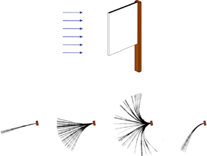
Experimental measurements. The four main dynamical regimes present at non-zero angle of attack are depicted in figure 3(a), which shows superimposed snapshots of the motion of a plate of  $AR=5$ at
  $\alpha =10^{\circ }$. Movies of the plate's motion for the four regimes can be viewed in the supplementary material available at https://doi.org/10.1017/jfm.2020.922. Figure 3(b) shows the maximum, minimum and average deflection angle,
  $\varPhi$, measured experimentally for the same plate as a function of non-dimensional flow speed,
  $\kappa ^{1/2}$. The dynamical regimes present in the plate's motion are demarcated in both figures. The deformed regime occurs at low flow speeds. In it the plate oscillates with small amplitude around a small-deflection position. As wind speed is increased, these oscillations grow into a flapping motion. This flapping motion is divided into two branches, the small-amplitude flapping regime and the large-amplitude flapping regime, which will be shown in the following sections to constitute distinct dynamics. Finally, as wind speed is further increased the plate enters the deflected regime, where it oscillates with small amplitude around a large-deflection position. The dominant non-dimensional frequency of oscillation of the plate,
  $\tilde {f}$, is presented as a function of
  $\kappa ^{1/2}$ in figure 3(d). It corresponds to the frequency at which the power spectrum of the flag's deflection presents its maximum peak. The spectrum is calculated using the fast Fourier transform of the deflection angle time series,
  $\varPhi (t)$. As a reference, the spectra for the
  $\alpha =10^{\circ }$ case are plotted in figure 4. Experimental frequency data throughout this text are presented only for flow speeds at which the spectrum presents a clear peak. In some cases, two distinct peaks are present; the peak of largest amplitude is taken as the dominant frequency. Because their amplitudes are similar, small changes result in the switching of the dominant peak, which is reflected as a jump in the presented frequency. An example of such a jump is the data point for
  $\kappa ^{1/2}=1.03$ in figure 3(d). A distinction should be made between these jumps in frequency and those present at the changes of dynamical regime, which correspond to a shift in the location of a single peak in the spectra.

Figure 3. Behaviour of an inverted cantilever plate at finite angle of attack ( $\alpha =10^{\circ }$). (a) Superimposed snapshots of the plate throughout its motion, depicting the four dynamical regimes. (b,c) Maximum (
 $\circ$, blue), minimum (
 $\circ$, red) and mean (
 $\bullet$) deflection angles,
  $\varPhi$, as a function of non-dimensional flow speed,
  $\kappa$. (d,e) Non-dimensional frequency of motion,
  $\tilde {f}$, as a function of non-dimensional flow speed,
  $\kappa$. The results were obtained experimentally for a plate of
  $AR=5$,
  $\mu =3.0$ and
  $Re\sim {O}(4)$ (a,b,d) and numerically for a two-dimensional inverted cantilever at
  $\mu =0.5,Re=200$. (c,e). The nomenclature employed for the different dynamical regimes is specified in (a,b).

Figure 4. Power spectra of the inverted cantilever plate's deflection measured experimentally for  $\alpha =10^{\circ }$ and varying flow speeds. The flow speeds highlighted with a bold frame correspond to the flapping regime as defined by (6.2). The scale varies and is specified for each spectrum.
Simulations. The maximum, minimum and average deflection angles obtained numerically, as described in § 3, for  $Re=200$ and
  $\alpha =10^{\circ }$, are displayed as a function of
  $\kappa ^{1/2}$ in figure 3(c). Despite the proximity of the simulations to a bifurcation in
  $Re$, the numerical results exhibit qualitative agreement with the experiments and show the presence of the same four dynamical regimes. The flow speed at which the small-amplitude flapping emerges is in reasonable agreement (
 $\kappa ^{1/2}=1.17$ for experiments,
  $\kappa ^{1/2}=1.25$ for numerical simulations). However, the flow speed at which the large-amplitude flapping starts differs significantly (
 $\kappa ^{1/2}=2.00$ for experiments,
  $\kappa ^{1/2}=1.65$ for numerical simulations) and the flow speed at which the large-amplitude flapping ceases sees moderate differences (
 $\kappa ^{1/2}=2.76$ for experiments,
  $\kappa ^{1/2}=2.6$ for numerical simulations). These differences are to be expected because the large-amplitude flapping motion is strongly dependent on the vortex shedding processes (Sader et al. Reference Sader, Cossé, Kim, Fan and Gharib2016a), which vary with the Reynolds number. The frequencies of motion,
  $\tilde {f}$, obtained numerically for the flag at
  $\alpha =10^{\circ }$ are presented in figure 3(e). The trend and values within the flapping motion are in agreement between experimental and numerical results (notice the difference in scale), and the jumps in frequency at the start and end of the flapping regime are present in both cases, despite significant variations in the values at deformed and deflected regimes.
Overall, the results obtained numerically and experimentally present appreciable differences but display the same general dynamical features. This is in agreement with results reported for an inverted cantilever plate at  $\alpha =0^{\circ }$, which show the characteristic qualitative features of the plate's dynamics and vortex wake to be fairly insensitive to Reynolds number for
  $Re>100$, while differences do occur in certain details as a function of
  $Re$ (Tang et al. Reference Tang, Liu and Lu2015; Shoele & Mittal Reference Shoele and Mittal2016). In this study, the majority of the results will be extracted from the experimental data, and the numerical results will be employed to gain a more detailed understanding of (i) the plate behaviour in the flapping regime, and (ii) the difference in flow structures between the small- and large-amplitude flapping regimes. Despite the non-negligible differences, the conclusions extracted from the numerical data in this text refer to the common general physics and are expected to hold for the large
  $Re$ case.
The dynamics of the  $AR=5$ plate – measured experimentally – and that of the analogous 2-D plate – used in the numerical results – will be analysed at moderate angles of attack in the following sections. The case of
  $\alpha =10^{\circ }$ will first be used as an example, because it embodies the general characteristics present for all angles of attack. The evolution of the plate's behaviour as the angle of attack is increased will then be studied experimentally. The corresponding subsections will draw heavily from figures 5–8, which were obtained experimentally for
  $AR=5$ and angles of attack between
  $0^{\circ }$ and
  $28^{\circ }$. Figure 5 displays the maximum, minimum and average deflection angles as a function of non-dimensional flow speed. Each panel corresponds to a different angle of attack, in
  $2^{\circ }$ increments. The value of these angles is specified in the top left corner of each panel. The dashed vertical lines mark the critical flow speeds at which the plate transitions between regimes. These flow speeds have been obtained following the method described in § 6. Figure 6 follows a similar organization and shows the values of the amplitude
  $A'$, which, as specified in § 2, is obtained as the maximum between
  $A_{max}-A_{min}$ and
  $|A_{max}|$. Figure 7 shows, in a similar manner, the non-dimensional dominant frequency of the plate's motion, while figure 8 shows the Strouhal number
  $St= fA'/U$. As described above, the frequencies in these last two cases are obtained as the largest peak in the spectra of the flag's motion.

Figure 5. Maximum ( $\circ$, blue), minimum (
 $\circ$, red) and mean (
 $\bullet$) deflection angles,
  $\varPhi$, measured experimentally for an inverted cantilever plate of
  ${AR}=5$ and
  $\mu =3.03$ as a function of non-dimensional flow speed,
  $\kappa$, and angle of attack,
  $\alpha$ (deg).

Figure 6. Non-dimensional maximum amplitude,  $A'$, measured experimentally for an inverted cantilever plate of
  ${AR}=5$ and
  $\mu =3.03$ as a function of non-dimensional flow speed,
  $\kappa$, and angle of attack,
  $\alpha$ (deg).

Figure 7. Non-dimensional frequency of motion,  $\tilde {f}$, measured experimentally for an inverted cantilever plate of
  ${AR}=5$ and
  $\mu =3.03$ as a function of non-dimensional flow speed,
  $\kappa$, and angle of attack,
  $\alpha$ (deg).

Figure 8. Strouhal number,  $St=f A'/U$, measured experimentally for an inverted cantilever plate of
  ${AR}=5$ and
  $\mu =3.03$ as a function of non-dimensional flow speed,
  $\kappa$, and angle of attack,
  $\alpha$ (deg).
5.2. Deformed regime
At small values of  $\kappa ^{1/2}$, inverted cantilever plates placed at zero angle of attack,
  $\alpha =0^{\circ }$, exhibit a straight regime, characterized by small oscillations around the zero-deflection equilibrium. As is expected, inverted cantilever plates clamped at non-zero angles of attack do not exhibit this behaviour. Instead, they undergo a small-amplitude oscillation around a small-deformation deflected equilibrium (figure 3b), with the deflection of this equilibrium increasing as
  $\kappa ^{1/2}$ is increased. The oscillations are periodic (i.e. the spectrum of the motion presents a clear peak) in most cases, with the exception of the lowest flow speeds. The aperiodic cases can be identified as those whose frequency has not been represented in figure 7. This regime will be referred to as deformed in this text, to make a distinction with the larger-deformation deflected regime that arises at flow speeds above the lock-off of the flapping motion. Inverted cantilever plates clamped at
  $\alpha =0^{\circ }$ transition from straight to deformed modes at a finite flow speed, while plates at a non-zero angles of attack are inherently in the deformed regime even at the smallest flow speeds.
The plate dynamics in the deformed regime are similar for all angles of attack, i.e. small oscillations around the deflected position (figure 5). The flow behaviour, however, exhibits significant changes as the angle of attack and flow speed are increased. For small angles of attack ( $\alpha \lesssim 10^{\circ }$) and low flow speeds, the deflection of the plate is small, and the flow remains attached. As flow speed is increased, the deflection increases accordingly and eventually reaches a critical value at which the flow separates. This transition towards separation and the subsequent initiation of vortex shedding marks the transition from the deformed regime to the small-amplitude flapping regime for plates at the low angles of attack (
 $\alpha \lesssim 10^{\circ }$), as will be shown in § 6. At high angles of attack (
 $\alpha \gtrsim 12^{\circ }$), on the other hand, the flow is separated for all flow speeds within the range considered in this study.
To further demonstrate how flow separation demarcates the transition from deformed to small-amplitude regimes at small angles of attack, snapshots obtained from the numerical simulations at  $\alpha =10^{\circ }$ and
  $\kappa ^{1/2}=1.15$ (in the deformed regime) and
  $\kappa ^{1/2}=1.25$ (in the small-amplitude regime) are shown in figures 9(a) and 9(b), respectively. The figures illustrate a full flapping cycle, with the first snapshot showing a flag position close to its positive peak and the remaining snapshots spaced roughly a quarter-period apart. For
  $\kappa ^{1/2}=1.15$, long vortical structures extend into the wake, but no vortex shedding is evident. On the other hand, for
  $\kappa ^{1/2}=1.25$ a 2S vortex shedding mode is clearly visible, despite the deflection of the plate being only slightly larger than for the
  $\kappa ^{1/2}=1.15$ case. Notice by comparison with figure 3(e) that this qualitative change in flow dynamics is commensurate with a jump in frequency of the flag's deflection dynamics. This jump in frequency is a result of the modification of aerodynamic forces when flow separation occurs. Thus, we utilize sharp jumps in frequency at low angles of attack,
  $\alpha$, and low flow speeds,
  $\kappa ^{1/2}$, to indicate the transition from an attached to a detached flow.

Figure 9. Snapshots from the 2-D numerical simulations for a plate at (a)  $\kappa ^{1/2} = 1.15$ and (b)
  $\kappa ^{1/2} =1.25$. Snapshot (i) corresponds to the plate being near its positive peak, and the remaining snapshots are spaced at approximately a quarter-period apart. Contours are of vorticity and are plotted in 34 levels between
  $-5$ and
  $5$ (these quantities are normalized using the free-stream speed
  $U$ and plate length
  $L$).
$L$).
Using this criterion, the flow speed,  $\kappa ^{1/2}$, at which the flow separates for plates at small angles of attack can be identified in the experimental results in figure 7 for
  $\alpha =2^{\circ }\text {--}10^{\circ }$. The maximum deflection angles of the plate at the flow speeds for which this jump occurs in the experimental data are
  $\varPhi _{sep}=8.8^{\circ },\ 9.8^{\circ },\ 13.0^{\circ },\ 12.4^{\circ }$ and
  $15.1^{\circ }$ at the angles of attack
  $\alpha =2^{\circ },\ 4^{\circ },\ 6^{\circ },\ 8^{\circ }$ and
  $10^{\circ }$, respectively. These deflection angles,
  $\varPhi _{sep}$, are within the range expected for separation to occur. Variations in their value between the different angles of attack are a result of the varying plate geometry and flow speed at separation. By contrast, for the plates at larger angles of attack (
 $\alpha \gtrsim 12^{\circ }$), the flow is separated for all wind speeds within the studied range. Thus, even the deformed regime is marked by flow separation and vortex shedding processes. Consistent with this, there is no longer a jump in frequency in transitioning from the deformed to small-amplitude flapping regimes (figure 7).
Finally, we note that the divergence instability that marks the onset of flapping for zero angle of attack,  $\alpha =0^{\circ }$ is no longer observed at non-zero angle of attack. As can be observed in figure 7, the plate frequency does not approach
  $f=0$. Instead, as
  $\kappa$ is increased the amplitude of the plate oscillations begins to grow, and a flapping motion develops.
5.3. Flapping regimes
The flapping motion of the inverted cantilever plate at non-zero angle of attack is divided into two distinct regimes: the small-amplitude flapping regime and the large-amplitude flapping regime. The differences between these two regimes are easily recognizable in figure 3. In the experimental results (figure 3b), as example, the small-amplitude flapping regime is present between  $\kappa _{lower}^{1/2}=1.17<\kappa ^{1/2}<2$ and the large-amplitude flapping regime lies between
  $2<\kappa ^{1/2}<\kappa _{upper}^{1/2}=2.69$, where
  $\kappa _{lower}$ and
  $\kappa _{upper}$ are used to denote the critical
  $\kappa$ for the initiation and cessation of flapping, respectively. The two regimes are separated by an abrupt change in amplitude and Strouhal number at all angles of attack, as well as a jump in frequency for angles of attack
  $\alpha <16^{\circ }$. Additionally, snapshots of the plate's motion in these flapping regimes, obtained through numerical simulations, are presented together with the corresponding vorticity contours in figure 10. These snapshots illustrate a full flapping cycle, with the first snapshot showing a flag position close to its positive peak and the remaining snapshots spaced roughly a quarter-period apart. They are obtained after allowing sufficient time for the flag to reach periodic flapping motion. Figure 10(a) corresponds to a flow speed in the small-amplitude flapping regime just before the transition to the large-amplitude flapping regime (
 $\kappa ^{1/2}=1.5$), while figure 10(b) corresponds to a flow speed just after the transition to large-amplitude flapping (
 $\kappa ^{1/2}=1.7$). From these snapshots it is evident that, in addition to the amplitude, frequency and Strouhal number, the flow behaviour also changes significantly between the small- and large-amplitude flapping regimes.

Figure 10. Snapshots from the 2-D numerical simulations for a plate at  $\alpha =10^{\circ }$ and (a)
  $\kappa ^{1/2} = 1.5$ and (b)
  $\kappa ^{1/2} =1.7$. Snapshot (i) corresponds to the plate being near its positive peak, and the remaining snapshots are spaced at approximately a quarter-period apart. Contours are of vorticity and are plotted in 34 levels between
  $-5$ and
  $5$ (these quantities are normalized using the free-stream speed
  $U$ and plate length
  $L$).
$L$).
The large-amplitude flapping regime displays the same dynamical characteristics as the large-amplitude flapping motion present at zero angle of attack, which has been thoroughly described in the inverted-flag literature. Through a detailed analysis of several factors – including the existence of vortex shedding and synchronization with the plate's motion, the value of the Strouhal number, the role of the unsteady fluid forces, and the effect of the Reynolds number, the fluid loading and the damping – Sader et al. (Reference Sader, Cossé, Kim, Fan and Gharib2016a) established this flapping motion to be a vortex-induced vibration (VIV). Some of the traits indicative of a VIV can be observed in the data presented here. The numerical simulations of figure 10(b) show the presence of vortex shedding that is synchronized with the motion of the flag. The large-amplitude flapping regime is associated with a 2P vortex shedding mode, as is evident in these simulations, in a similar manner to the large amplitude flapping mode of the zero-angle-of-attack case (Yu et al. Reference Yu, Liu and Chen2017; Goza et al. Reference Goza, Colonius and Sader2018). The peak Strouhal number occurs at  $\kappa ^{1/2}=2$ in the experimental results, and is in the range
  $St=0.18\text {--}0.19$ for angles
  $\alpha \lesssim 15^{\circ }$, decreasing rapidly for larger angles of attack (figure 8). These Strouhal numbers are characteristic of lock-on in VIVs, marking the synchronization of vortex shedding with the resonant frequency of the plate. The frequency of motion of the plate decreases as flow speed is increased (figure 7), as is characteristic of vortex-induced vibrations in heavy fluid loading (
 $\mu \lesssim {O}(1)$). The Strouhal number decreases commensurately as a consequence of the constant amplitude
  $A'$ (figure 6) derived from the problem's geometry (increased deflections only result in the plate bending backwards beyond
  $\varPhi =90^{\circ }$). The minimum Strouhal numbers within the large-amplitude flapping regime are reached at lock-off and have a value of
  $St \approx 0.08$ for the smallest angles of attack (
 $\alpha \lesssim 4^{\circ }$) and
  $St \approx 0.11$ for the remaining angles.
The small-amplitude flapping regime, on the other hand, presents different characteristics. The vortex dynamics is visible in the numerical simulations of figure 10(a). A single vortex pair is shed as the flag moves from the positive to the negative deflection peak. No vortex structures form, however, on the second half of the cycle, despite the absolute value of the minimum deflection being large ( $\varPhi =-21^{\circ }$). While some vorticity is generated at the leading edge during this lower motion, no coherent vortex core is formed. The overall shedding pattern therefore corresponds to a 2S mode. This mode can also be observed at the lowest flow speed of the small-amplitude flapping regime,
  $\kappa ^{1/2}=1.25$ in figure 9(b), and can, therefore, be expected to be present throughout the entirety of the regime.
The small- and large-amplitude flapping motions of the inverted cantilever plate show striking similarities to the initial and lower branches present in the vortex-induced vibrations of a circular cylinder (Sarpkaya Reference Sarpkaya2004; Williamson & Govardhan Reference Williamson and Govardhan2004). However, the  $St$ within the small-amplitude flapping regime, determined experimentally using the frequency of motion, varies between
  $St=0.02$ and
  $St=0.13$ while the
  $St$ of a rigid flat plate at an angle of attack, calculated using the shedding frequency, is approximately
  $St \approx 0.15$ (Knisely Reference Knisely1990). This significantly lower value of the frequency of motion compared to the vortex shedding frequency is not indicative of a classic vortex-induced vibration (Sarpkaya Reference Sarpkaya2004; Williamson & Govardhan Reference Williamson and Govardhan2004). Although a more comprehensive analysis is required to fully discard a VIV as origin of the small-amplitude flapping motion – the difference in geometry between rigid and deformed plate may be behind this disparity in relative frequency values – the discrepancies point towards an origin of the small-amplitude flapping motion different from a VIV. The spectra of the plate's motion for flow speeds leading to the appearance of the small-amplitude flapping mode, visible in figure 4 for the experimental results at
  $\alpha =10^{\circ }$, show a single peak increasing in amplitude as the critical flow speed
  $\kappa _{lower}$ is approached, and not two coalescing peaks. Therefore, the presence of a coupled-mode instability, such as coupled-mode flutter, is unlikely. The presence of a non-zero frequency at the emergence of small-amplitude flapping (figure 7) also eliminates the possibility of a Paidoussis-type flutter mechanism (Paidoussis Reference Paidoussis2014), observed by Tavallaeinejad et al. (Reference Tavallaeinejad, Païdoussis, Legrand and Kheiri2020b) in a linear stability analysis of the inverted cantilever at zero angle of attack. The most probable mechanism is that the plate's motion is dominated by the quasi-steady fluid mechanics, with the plate undergoing a limit-cycle oscillation similar to stall flutter. This hypothesis is supported by the observation, shown in § 6 (figure 12), that at small angles of attack small-amplitude flapping is only initiated once flow separation occurs. Further investigations, however, are necessary to unequivocally characterize the nature of this instability. It should be noted that plates at higher angles of attack (
 $\alpha >16^{\circ }$) exhibit a discontinuity in flapping amplitude and oscillation frequency at a constant value of
  $\kappa ^{1/2}\approx 1.5$, which may be indicative of a transition to a different driving mechanism within the small-amplitude flapping regime.
5.4. Deflected regime
In the large-amplitude flapping regime, the frequency of motion of the inverted cantilever plate decreases as flow speed is increased (figure 7). When the value of the plate's resonant frequency becomes sufficiently different to that of the vortex shedding frequency, the plate's motion ceases to lock-on and the large-amplitude flapping motion disappears, giving rise to the deflected regime. Between the flapping and deflected regimes, a bi-stable region, where either regime can exist, is experimentally observed. In this region, two different behaviours can occur. In the first case, the plate switches what appears to be randomly from one state to the other, resulting in the chaotic regime that has been reported for inverted flags at zero angle of attack (Sader et al. Reference Sader, Cossé, Kim, Fan and Gharib2016a; Goza et al. Reference Goza, Colonius and Sader2018). The chaotic regime occurs for a narrow band of flow speeds, provided in table 1, at small angles of attack ( $\alpha \lesssim 4^{\circ }$). In the second case, the plate is either continuously flapping or continuously deflected depending on its initial condition. Bi-stability was observed for angles of attack up to
  $\alpha <8^{\circ }$. Interestingly, the spectrum of the plate's motion (figure 4) transitions from presenting a single dominant peak in the deformed and flapping regimes to presenting two clear peaks in the deflected regime. The frequency of the second peak, however, is too small to correspond to the vortex shedding frequency. It may correspond to either sub-harmonics of unsteady fluid forces or a resonant frequency of the plate.
Table 1. Range of non-dimensional flow speeds for which the chaotic regime occurs.

The critical flow speed,  $\kappa _{upper}$, at which the plate enters the deflected regime decreases with angle of attack (figure 5). Cossé (Reference Cossé2014) observed that, independently of angle of attack, the inverted cantilever shows a similar deflected shape at the emergence of the deflected regime. This is corroborated in the present experimental measurements. The average deflection angle,
  $\bar {\varPhi }$ at the smallest flow speed where the plate first enters the deflected regime is virtually constant, with an average of
  $\bar {\varPhi }=46.7^{\circ }$ and a standard deviation of only
  $\pm 1.2^{\circ }$. A similar value of
  $\bar {\varPhi }=48.23^{\circ }\pm 3.42^{\circ }$ is observed for the plate of
  $AR=2$ that will be discussed in § 7. The value of this angle for the numerical results obtained for
  $\alpha =10^{\circ }$ is, on the other hand
  $\bar {\varPhi }=61^{\circ }$, with the difference in angle with respect to the experimental results being most likely caused by the differences in
  $Re$ and
  $\mu$.
6. Evolution with angle of attack
The four main dynamical regimes present at moderate angles of attack (deformed, small-amplitude flapping, large-amplitude flapping and deflected) have been analysed in detail in the previous sections. The general evolution of the plate's dynamics with increasing angle of attack is visible in figures 5–8. The evolution of the critical transition speeds between the different regimes is analysed in detail in this section.
The absence of a divergence instability for  $\alpha >0^{\circ }$ and the gradual increase of the plate's oscillation amplitude as flow speed is increased pose a challenge in defining a critical transition speed,
  $\kappa _{lower}$, from deformed to small-amplitude flapping regimes. The method proposed by Cossé et al. (Reference Cossé, Sader, Kim, Huertas Cerdeira and Gharib2014) specifies
  $\kappa _{lower}$ as the speed at which the plate reaches an amplitude of motion that is a chosen fraction of the maximum flapping amplitude. The selection of this fraction, however, is arbitrary, and its variation results in significant changes in the value of the critical speed. An alternate approach, based on the spectra of the plate's deflection angle, is proposed here. The difference between flapping motions and motions with no resonance is distinguishable by eye in figure 4. In the flapping motions, the spectra show a single crisp peak that corresponds to the resonant frequency, while in the motions with no resonance the spectrum appears noisy due to the presence of multiple frequencies, even if a peak is present. The flapping regime is therefore defined as the range of flow speeds at which these spectra present a single crisp peak. In order to mathematically define this region, a bi-Gaussian function is fit to each fast Fourier Transform (FFT), normalized such that its maximum value is equal to one, and the sum of squares error (SSE) is calculated as
 \begin{equation} SSE=\sum_1^{n}(y_i-\psi(\,f_i))^2, \end{equation}
where  $n$ is the number of frequency points in the FFT,
  $y_i$ is the value of the FFT at the frequency
  $f_i$ and
  $\psi (\,f_i)$ is the value of the fit at
  $f_i$. The SSE provides a measure of the dispersion of the data points around the fit. The values of the SSE for
  $\alpha =10^{\circ }$ are plotted in figure 11(a). The SSE displays a low-value plateau at the flow speeds at which flapping occurs, with its value increasing in the deformed and deflected regimes. Consequently, the flapping regime is chosen to be the range of
  $\kappa$ at which the SSE is within this low-value plateau
 \begin{equation} SSE \left( \frac{FFT}{max(FFT)} \right) < 1.7. \end{equation}
Figure 11. Sum of squares error for a bi-Gaussian fit to the power spectra of the plate's motion ( $\circ$) measured experimentally for an angle of
  $\alpha =10^{\circ }$ and threshold defining the flappingregime (–).
Although different angles of attack presented different defining thresholds, the value of 1.7 was chosen as a reasonable representative value for all angles. This threshold is considered less arbitrary than the maximum-amplitude fraction employed by Cossé et al. (Reference Cossé, Sader, Kim, Huertas Cerdeira and Gharib2014) because it is chosen to separate the more clearly defined plateau. Alternative approaches to identifying this flapping region are certainly possible, and a more rigorous approach may be developed as our knowledge of the underlying physics expands. Even so, the principal conclusions presented in this section are expected to hold. The FFTs corresponding to the flapping regime, as defined by (6.2), are identified with a bold frame in figure 4, for  $\alpha =10^{\circ }$. The corresponding critical flow speeds for the onset and end of the flapping regime are marked with vertical dashed lines in figure 3(b). While the transition from deformed to flapping regimes is smooth, the transition from flapping to deflected regimes is well defined and corresponds to an abrupt decrease in the amplitude of motion. The limits defined by (6.2) capture this transition and the overall flapping region well.
The critical flow speeds at which transitions between regimes occur are represented in figure 12 for different angles of attack. The brown triangles are  $\kappa _{lower}$, which is the transition from deformed to small-amplitude flapping regimes as defined by (6.2). The red squares are
  $\kappa _{upper}$, the flow speed at which resonance ends, again using (6.2). The green triangles represent
  $\kappa _{sep}$, the flow speed at which the flow separates, which corresponds to a jump in frequency in figure 7 for angles
  $\alpha \leqslant 10^{\circ }$. The blue circles delineate the transition from small- to large-amplitude flapping, determined by a jump in amplitude and frequency in figures 5–8. The black rhombuses correspond to the flow speed at which large-amplitude flapping gives way to the deflected regime,
  $\kappa _{def}$, marked by a sharp decrease in amplitude in figure 5.

Figure 12. Critical non-dimensional flow speeds measured experimentally as a function of angle of attack. Flow speed for flow separation,  $\kappa _{sep}$ (
 $\nabla$, green), start of small-amplitude flapping regime (as defined by (6.2)),
  $\kappa _{lower}$ (
 $\triangle$, brown), end of resonance (as defined by the same equation),
  $\kappa _{upper}$ (
 $\square$, red), start of deflected regime,
  $\kappa _{def}$ (
 $\diamond$) and start of large-amplitude flapping regime (
 $\circ$, blue).
The critical flow speed for transition from deformed to small-amplitude flapping regimes,  $\kappa _{lower}$, shows different behaviour for small (
 $\alpha \lesssim 10^{\circ }$) and large (
 $\alpha \gtrsim 10^{\circ }$) angles of attack. At small angles, it follows the trend of the flow speed required for the flow to separate,
  $\kappa _{sep}$, decreasing as angle of attack is increased (figure 12). Following the discussion in § 5.3, it is reasonable to assume a separated flow is required for the small-amplitude flapping regime to develop. This plot corroborates that at the emergence of small-amplitude flapping the flow over the plate is always separated. Thus, vortex shedding occurs and the quasi-steady forcing is nonlinear. For larger angles of attack (
 $\alpha \gtrsim 10^{\circ }$), on the other hand, the flow is always separated within the range of
  $\kappa$ studied. At low
  $\kappa$ the plate remains in the deflected regime despite the flow being separated. Therefore, there must be other requirements in addition to flow separation for the small-amplitude flapping regime to develop, which may be related to the stability of the deformed position. The critical flow speed at these larger angles decreases significantly slower as the angle of attack is increased. At the highest angles of attack (
 $\alpha \gtrsim 24^{\circ }$), the transition flow speed increases abruptly and rapidly, leading to disappearance of the small-amplitude flapping regime.
The critical flow speed at which the plate enters the deflected regime,  $\kappa _{def}$, and the critical flow speed at which the resonance ceases,
  $\kappa _{upper}$, are plotted together in figure 12. Both speeds have been extracted from the same data set, eliminating any differences caused by the bi-stable nature of the plate in this region. As expected, these two speeds overlap, with small disparities being likely caused by experimental error and the limited precision of the identifying method (6.2). The critical flow speed at which the flag transitions to the deflected regime,
  $\kappa _{def}$, decreases as the angle of attack is increased due to the increased fluid damping. This decrease in
  $\kappa _{def}$ is linear with angle of attack.
Moreover, the critical flow speed at which the plate enters the large-amplitude flapping regime, represented by blue circles in figure 12, is strikingly constant for all  $\alpha$, at a value of
  $\kappa ^{1/2}=2$. Linear fits to both critical flow speeds have been included in figure 12. Due to these trends, the range of flow speeds at which the large-amplitude flapping motion occurs decreases with increasing angle of attack. The large-amplitude flapping regime ceases to exist at an angle of
  $\alpha =26.8^{\circ }$, calculated using the linear fits. The small-amplitude flapping motion is present at angles beyond this
  $\alpha =26.8^{\circ }$ value, but not significantly higher. It ceases to exist for
  $\alpha \approx 28^{\circ }$. At larger angles (
 $\alpha \gtrsim 28^{\circ }$) the deformed and deflected regimes merge into a single common regime, where the plate flexes with continuously increasing deflection angle and oscillates with small amplitude around this position.
The angular amplitude of motion in the large-amplitude flapping regime is approximately independent of angle of attack for  $\alpha \leqslant 14^{\circ }$. It decreases rapidly for angles greater than that value (figure 5). This result is in agreement with the threshold obtained by Shoele & Mittal (Reference Shoele and Mittal2016), who observed the amplitude to notably decline for angles beyond
  $\alpha =15^{\circ }$. The Strouhal number follows a similar trend, diminishing rapidly for angles greater than
  $\alpha =14^{\circ }$ (figure 8). The energy harvesting performance of the inverted flag is therefore severely limited beyond
  $\alpha =14^{\circ }$, both due to the decrease in the flapping amplitude and the decrease in range of speeds at which flapping occurs.
7. Effect of aspect ratio
The experimental measurements reported in § 5 for an inverted cantilever plate of aspect ratio  $AR=5$ are repeated here for a plate of
  $AR=2$, with the objective of highlighting the most prominent differences. The obtained data are presented in a similar manner: the maximum, minimum and mean deflection angles,
  $\varPhi$, are shown in figure 13, the amplitude,
  $A'$, in figure 14, the frequency,
  $\tilde {f}$, in figure 15 and the Strouhal number,
  $St$, in figure 16. The corresponding values for the
  $AR=5$ plate are included for comparison in these figures. The data points corresponding to the chaotic region have been highlighted in black in figure 13. As is evident from these figures, the behaviour of the plate of
  $AR=2$ presents notable differences with respect to the plate of
  $AR=5$.

Figure 13. Maximum ( $\diamond$, blue), minimum (
 $\diamond$, red) and mean (
 $\bullet$) deflection angles,
  $\varPhi$, measured experimentally for an inverted cantilever plate of
  $AR=2$ and
  $\mu =3.11$ as a function of non-dimensional flow speed,
  $\kappa$, and angle of attack,
  $\alpha$. Maximum and minimum deflection angles for an inverted cantilever plate of
  $AR=5$ (
 $\circ$) for reference.

Figure 14. Maximum non-dimensional amplitude,  $A'$ (
 $\diamond$), measured experimentally for an inverted cantilever plate of
  $AR=2$ and
  $\mu =3.11$ as a function of non-dimensional flow speed,
  $\kappa$, and angle of attack,
  $\alpha$. Maximum amplitude for an inverted cantilever plate of
  $AR=5$ (
 $\circ$) for reference.

Figure 15. Non-dimensional frequency of motion,  $\tilde {f}$ (
 $\diamond$), measured experimentally for an inverted cantilever plate of
  $AR=2$ and
  $\mu =3.11$ as a function of non-dimensional flow speed,
  $\kappa$, and angle of attack,
  $\alpha$. Frequency of motion for an inverted cantilever plate of
  $AR=5$ (
 $\circ$) for reference.

Figure 16. Strouhal number,  $St=f A'/U$ (
 $\diamond$), measured experimentally for an inverted cantilever plate of
  $AR=2$ and
  $\mu =3.11$ as a function of non-dimensional flow speed,
  $\kappa$, and angle of attack,
  $\alpha$. Strouhal number for an inverted cantilever plate of
  $AR=5$ (
 $\circ$) for reference.
At low flow speeds, the plate of  $AR=2$ is in the deformed regime and oscillates with small amplitude around a small-deflection equilibrium. In this regime, the power spectra of the
  $AR=2$ plate, depicted in figure 17(a), present two peaks, which may be indicative of the effect of the second length scale (height,
  $H$) that introduces a second characteristic frequency. The transition to the small-amplitude flapping regime occurs in a similar manner to the higher-aspect-ratio case, with the lower of the two frequency peaks growing in amplitude and without a coalescence of peaks being observed (figure 17a). The jump in frequency indicative of flow detachment at small angles of attack is, nonetheless, no longer visible.

Figure 17. Power spectra of the deflection of an inverted cantilever plate of  $AR=2$ at (a)
  $\alpha =10^{\circ }$ and (b)
  $\alpha =30^{\circ }$ obtained experimentally at varying flow speeds. The scale varies and is specified for each spectrum.
For  $AR=2$, distinct small- and large-amplitude flapping regimes can only be recognized at small angles of attack (
 $\alpha \leqslant 8^{\circ }$). At these small angles, an abrupt increase in amplitude and Strouhal number signals the transition between the two regimes. Unlike in the
  $AR=5$ case, this transition does not coincide with the flow speed where the
  $St$ reaches its maximum value (figure 16). The flow speed where the
  $St$ peak occurs is, however, strikingly equal for both aspect ratios (
 $\kappa ^{1/2}\approx 2$). At large angles of attack (
 $\alpha > 8^{\circ }$), on the other hand, the
  $AR=2$ plate does not present evident small- and a large-amplitude flapping regimes. For these large angles, the variables that define the motion of the plate vary smoothly as flow speed is increased (figures 13–16). This smooth variation may be caused by the existence of tip vortices and three-dimensionality in the vortex shedding, that result in the presence of a range of frequency values instead of a single defined frequency. Remarkably, the plate of
  $AR=5$ presented a discontinuity in the amplitude of motion at a flow speed of
  $\kappa ^{1/2}\approx 1.5$ for angles
  $\alpha >16^{\circ }$ that is also present at the same threshold and flow speed for
  $AR=2$.
The absence of a pronounced large-amplitude flapping regime for  $AR=2$ and angles of attack
  $\alpha >8^{\circ }$ is marked by lower flapping amplitudes and Strouhal numbers with respect to the
  $AR=5$ plate, with the difference in minimum deflection angle being particularly significant (figure 13). This discrepancy initially occurs only at the lower flow speeds of the large-amplitude flapping regime, but extends to the full range of speeds for
  $\alpha >14^{\circ }$. Due to the reduced amplitude and Strouhal numbers and the differences in behaviour with respect to the
  $AR=5$ plate, the nature of the flapping motion of the
  $AR=2$ plate at
  $\alpha > 8^{\circ }$ remains unclear. As the flow speed is further increased, this flapping motion gives way to the chaotic regime. This regime is more pronounced for the
  $AR=2$ plate than for the
  $AR=5$ case, occurring at a larger range of flow speeds and angles of attack (
 $\alpha \lesssim 16^{\circ }$). If the flow speed is further increased, the plate finally enters the deflected regime, where it oscillates around a large-deflection position in a similar manner to the
  $AR=5$ plate.
The critical non-dimensional flow speeds,  $\kappa$, at which the
  $AR=2$ plate transitions between regimes are shown in figure 18. The flow speed for initiation of flapping,
  $\kappa _{lower}$, has been obtained following (6.2). The remaining velocities have been determined by the observation of abrupt changes in the flag's behaviour. The flow speed at which the large-amplitude flapping regime ends for
  $AR=2$ follows a linear trend with angle of attack, but has a more pronounced slope than the
  $AR=5$ case. Similarly to the plate of
  $AR=5$, this results in the flapping motion of the
  $AR=2$ plate being practically non-existent for an angles of attack beyond
  $\alpha =28^{\circ }$.

Figure 18. Critical non-dimensional flow speeds measured experimentally as a function of angle of attack for a plate of  $AR=2$. Start of flapping regime (as defined by (6.2)),
  $\kappa _{lower}$ (
 $\triangle$, brown), start of large-amplitude flapping regime (
 $\circ$, blue), start of chaotic regime (
 $\nabla$, orange) and start of deflected regime,
  $\kappa _{def}$ (
 $\diamond$).
In addition to the above analysed data, an angle of attack of  $\alpha =30^{\circ }$ was investigated, the data from which are presented in figures 13–16. Interestingly, a new resonant motion is observed that presents amplitude and frequency response characteristics distinct from those of the flapping regimes observed for the
  $AR=2$ plate at
  $\alpha <30^{\circ }$. At the lower flow speeds, the power spectra of the motion, displayed in figure 17(b), show the existence of two peaks, which approach each other at the onset of the large-amplitude motion of the plate. The proximity of these peaks suggests the presence of a coupled-mode mechanism, such as coupled-mode flutter. The detailed analysis of this new resonant motion is beyond the scope of the present study, but these results highlight the variety of phenomena that may arise at angles of attack intermediate to those typically studied,
  $\alpha =0^{\circ },\ 90^{\circ }$ and
  $180^{\circ }$, that may be of interest in future investigations.
8. Conclusions
This study has reported and analysed the dynamics of an inverted cantilevered plate placed at a moderate angle of attack ( $\alpha \leqslant 30^{\circ }$) to a uniform flow. First, a plate of large aspect ratio (
 $AR=5$) was investigated experimentally. At non-zero angle of attack, four distinct dynamical regimes were identified as the non-dimensional flow speed,
  $\kappa$, is increased: deformed (small oscillations around a small-deflection equilibrium), small-amplitude flapping, large-amplitude flapping and deflected (small oscillations around a large deflection equilibrium). A comparison with 2-D numerical simulations revealed that the qualitative dynamical features remain unchanged for low Reynolds numbers (
 $Re=200$), although variations in the characteristic flow speeds, amplitudes and frequencies are present.
The data obtained for the  $AR=5$ case showed that the plate, initially in the deformed regime, does not undergo a divergence instability, but exhibits a gradual increase in the amplitude of oscillation as it enters the small-amplitude flapping regime. A new method based on the power spectra of the plate's deflection was proposed to identify the critical flow speed at which small-amplitude flapping is initiated. For small angles of attack (
 $\alpha \leqslant 10^{\circ }$) this transition occurs at the flow speed that generates a plate deflection large enough for the flow to separate. For large angles of attack (
 $\alpha >10^{\circ }$) the flow is always separated and an additional instability, which remains to be fully characterized, determines this critical flow speed. The small-amplitude flapping regime was argued to be a limit-cycle oscillation produced by the quasi-steady fluid forcing and was associated with a 2S vortex shedding mode.
At a flow speed of  $\kappa ^{1/2}=2$, which was found to be independent of angle of attack, the plate was observed to transition to the large-amplitude flapping regime. This transition is marked by an abrupt change in flapping amplitude, Strouhal number and frequency of motion (the latter for
  $\alpha <16^{\circ }$ only) as well as a shift to a 2P vortex shedding mode. The large-amplitude flapping regime presents the same characteristics as the flapping motion observed at zero angle of attack, which has been established to constitute a vortex-induced vibration (Sader et al. Reference Sader, Cossé, Kim, Fan and Gharib2016a). As the flow speed was increased, the plate transitioned to the deflected regime. The flow speed at which this transition occurs decreases linearly with angle of attack. Consequently, the range of flow speeds at which the large-amplitude flapping motion is present decreases with increasing angle of attack. At an angle of attack of
  $\alpha =26.8^{\circ }$ the large-amplitude flapping motion ceases to exist. The small-amplitude flapping motion disappears at angles beyond
  $\alpha \approx 28^{\circ }$.
A subsequent set of measurements were performed on a plate of aspect ratio  $AR=2$ and revealed contrasting dynamics. Although the main dynamic regimes are still present, the distinction between small- and large-amplitude flapping motions is no longer evident for
  $\alpha >8^{\circ }$, with the amplitude and frequency of motion varying smoothly across the flapping regimes. This was argued to be a result of the three-dimensional vortex shedding. As a result of the modified dynamics, the flapping amplitude is fairly decreased with respect to the large-aspect-ratio plate for angles of attack above
  $\alpha \gtrsim 8^{\circ }$. A new distinct large-amplitude motion was observed to appear at
  $\alpha =30^{\circ }$, highlighting the diversity of dynamics that may be present at larger angles of attack.
Acknowledgements
C.H.-C. and M.G. acknowledge funding from the Gordon and Betty Moore Foundation. A.G. and T.C. acknowledge funding from Robert Bosch LLC through the Bosch Energy Research Network Grant (grant number 07.23.CS.15), and from the AFOSR (grant number FA9550-14-1-0328). J.S. acknowledges funding from the Australian Research Council Centre of Excellence in Exciton Science (CE170100026) and the Australian Research Council grants scheme.
Declaration of interests
The authors report no conflict of interest.
Supplementary movies
Supplementary movies are available at https://doi.org/10.1017/jfm.2020.922.


