


1. Introduction
Hydrodynamic forces arising from fluid inertia in particle-laden flows can induce a dynamics not observed in purely viscous (zero Reynolds number) flows. Specifically, the phenomenon, known as ‘inertial lift’, can induce particle migration across streamlines in ambient, confined unidirectional flow, resulting in a focusing of the particles at a given equilibrium position. In confined pressure-driven flow, inertial lift primarily arises from two sources: wall-induced lift, and shear-gradient lift, which act to force the particle away from and toward the confining boundary, respectively (Gou et al. Reference Gou, Jia, Wang and Sun2018). Other sources of inertial lift include the ‘Saffman lift’ (Saffman Reference Saffman1965) and the ‘Magnus effect’ (Rubinow & Keller Reference Rubinow and Keller1961). The former refers to the lift force on a particle due to its ‘slip’ velocity relative to the ambient flow streamline passing through its centre, as would occur for a non-neutrally buoyant particle in shear flow, for example. The latter refers to the lift force due to the combined translation and rotation of a particle. These two sources of lift are generally weak compared to wall-induced and shear-gradient lift in microfluidic devices, for example (Martel & Toner Reference Martel and Toner2014). It should be noted, however, that partitioning the lift force into the aforementioned sources is somewhat artificial, as all contributions arise from the integral of the hydrodynamic traction over the particle surface. Interest in inertial lift has increased recently due to applications in microfluidic devices, to affect particle separations without external forces (e.g. magnetic or electric) that could be harmful to the entity to be separated. Inertial lift has been harnessed to perform rapid separations on blood cells (Nivedita & Papautsky Reference Nivedita and Papautsky2013), cancer cells (Hur, Mach & Di Carlo Reference Hur, Mach and Di Carlo2011), Escherichia coli (Mach & Di Carlo Reference Mach and Di Carlo2010) and biodiesel-producing algae (Li et al. Reference Li, Munoz, Goda and Di Carlo2017), for instance.
The study of inertial lift was motivated by the experimental observations of Segre & Silberberg (Reference Segre and Silberberg1961, Reference Segre and Silberberg1962). In this seminal work, they observed the migration of neutrally buoyant spheres in a circular tube of diameter  $H$ in pressure-driven flow of a Newtonian fluid with characteristic speed
  $U_m$ and kinematic viscosity
  $\nu$. They observed a migration of the particles transverse to the direction of flow at channel Reynolds numbers
  ${\textit {Re}}_c=U_mH/\nu$ between 2 and 60 and showed that, due to fluid inertia, the particles focused at an transverse equilibrium position around
  $0.3H$ from the channel centre, moving further toward the wall as
  ${\textit {Re}}_c$ increased. Their observations sparked an array of studies of inertial lift using asymptotic analysis at small particle Reynolds numbers. Rubinow & Keller (Reference Rubinow and Keller1961) studied a sphere of radius
  $a$ translating and rotating at velocities of
  $\boldsymbol {U}_{\boldsymbol {p}}$ and
  $\boldsymbol {\varOmega }_{\boldsymbol {p}}$, respectively, through an unbounded, quiescent fluid of density
  $\rho$ and viscosity
  $\mu$ using matched asymptotic expansions. They calculated a (Magnus-type) lift force transverse to the particle motion as
  $\boldsymbol {F}_{\boldsymbol {L}} \sim {\rm \pi}a^3 \rho \boldsymbol {\varOmega }_{\boldsymbol {p}} \times \boldsymbol {U}_{\boldsymbol {p}}$ at small translational particle Reynolds numbers,
  ${\textit {Re}}_t=U_p a/\nu$, where
  $U_p=|\boldsymbol {U}_{\boldsymbol {p}}|$. Saffman (Reference Saffman1965) performed matched asymptotic expansions to calculate the lift force on a sphere in unbounded shear flow of velocity gradient
  $G$, translating at a ‘slip velocity’
  $\boldsymbol {U}_{\boldsymbol {s}}$ relative to the undisturbed streamline at its centre. He calculated a lift force of
  $|\boldsymbol {F}_{\boldsymbol {L}}| \sim 6.46 a \mu |\boldsymbol {U}_{\boldsymbol {s}}|{\textit {Re}}_p^{1/2}$, directed to force the particle toward streamlines moving opposite to its translation, at small shear particle Reynolds numbers,
  ${\textit {Re}}_p=Ga^2/\nu$, under the restriction that
  ${\textit {Re}}_s \ll {\textit {Re}}_p^{1/2} \ll 1$, where
  ${\textit {Re}}_s=U_sa/\nu$ is the particle slip Reynolds number. Cox & Brenner (Reference Cox and Brenner1968) used a regular perturbation analysis to study the lift force on an arbitrarily shaped neutrally buoyant particle of characteristic size
  $a$ in planar, confined Poiseuille flow, at a distance
  $d$ from the channel wall, at small particle Reynolds number
  ${\textit {Re}}_p$, and small relative particle size
  $a/d$. They derived an integral formula for the inertial lift on the particle and an equation for its transverse migration, but did not explicitly predict the equilibrium position of the particle. Ho & Leal (Reference Ho and Leal1974) used the reciprocal theorem to examine a neutrally buoyant sphere in planar confined shear and Poiseuille flow at small
  ${\textit {Re}}_p$ and small confinement ratio
  $\kappa =a/H$, where
  $H$ in this case is the channel height. Their analysis showed that a sphere in shear flow has an equilibrium position at the centre of the channel, and a sphere in Poiseuille flow has an equilibrium position
  $0.3H$ from the centre of the channel. Schonberg & Hinch (Reference Schonberg and Hinch1989) used a singular perturbation analysis to investigate a neutrally buoyant sphere in confined Poiseuille flow at small
  ${\textit {Re}}_p$ and
  $\kappa$, but
  ${\textit {Re}}_c=O(1)$. A singular perturbation analysis is required here as the inertia-dominated outer region occurs within the channel at
  ${\textit {Re}}_c=O(1)$, whereas Cox & Brenner (Reference Cox and Brenner1968) and Ho & Leal (Reference Ho and Leal1974) used regular perturbations due to the flow being entirely viscous dominated at
  ${\textit {Re}}_c\ll 1$. Schonberg & Hinch (Reference Schonberg and Hinch1989) showed that the equilibrium position of the sphere was at around
  $0.3H$ and moved toward the wall of the channel as
  ${\textit {Re}}_c$ increased, qualitatively matching the observations of Segre & Silberberg, although those experiments were in a circular tube.
While inertial lift has been extensively studied in confined Poiseuille flow, there have been relatively few investigations in confined simple shear flow. This is surprising to us, since simple shear flow can readily be realized in rheometers, for example. Drew (Reference Drew1988) performed a perturbation analysis for a sphere translating relative to a shear flow in the presence of a distant wall at small  ${\textit {Re}}_p$, thereby extending Saffman's analysis. The calculated wall-induced lift force was shown to always be smaller than the unbounded lift force and thus to not alter the direction of migration. McLaughlin (Reference McLaughlin1991) used matched asymptotic expansions to extend Saffman's analysis to larger
  ${\textit {Re}}_s=U_sa/\nu$, such that
  ${\textit {Re}}_s \geqslant {\textit {Re}}_p^{1/2}$, with both
  ${\textit {Re}}_s$ and
  ${\textit {Re}}_p$ remaining small compared to unity. His analysis revealed that the lift force decreases rapidly as
  ${\textit {Re}}_s/{\textit {Re}}_p$ becomes large, as the particle motion reduces to that of translation in an essentially quiescent fluid. Later, McLaughlin (Reference McLaughlin1993) connected these previous analyses by using matched expansions to analyse lift for a particle due to both a distant wall and at
  ${\textit {Re}}_s \geqslant {\textit {Re}}_p^{1/2}$. The combination results in a particle migrating either toward or away from the wall. Asmolov (Reference Asmolov1999) studied the lift force on a neutrally buoyant sphere in shear flow bounded by a single wall using matched expansions. He showed that the lift force always points away from the wall and as such a particle would not reach an equilibrium position. Ekanayake et al. (Reference Ekanayake, Berry, Stickland, Dunstan, Muir, Dower and Harvie2020) investigated the lift and drag forces acting on a sphere in shear flow bounded by a single wall using numerical computations at low
  ${\textit {Re}}_s$. They revealed that both the forces are strongly dependent on shear rate and propose wall-shear-based lift and drag correlations. Feng, Hu & Joseph (Reference Feng, Hu and Joseph1994) performed finite element simulations to calculate the trajectory of a neutrally buoyant infinite circular cylinder in confined shear flow at non-zero particle Reynolds numbers,
  ${\textit {Re}}_p=Ga^2/\nu$, where
  $a$, in this two-dimensional problem, is the radius of the cylinder cross-section. This study revealed that, up to
  ${\textit {Re}}_p=0.625$, the equilibrium position for a particle in bounded shear flow remained at the centre of the channel for a cylinder of
  $\kappa =0.125$. In our previous work, lattice Boltzmann simulations were performed to extend the study of a neutrally buoyant circular cylinder in confined shear flow to higher
  ${\textit {Re}}_p$ (Fox, Schneider & Khair Reference Fox, Schneider and Khair2020). Our analysis revealed a supercritical pitchfork bifurcation of the equilibrium position above a critical
  ${\textit {Re}}_p$ dependent on
  $\kappa$, switching from a single stable equilibrium position at the centre of the channel to three equilibrium positions: two stable equilibria equidistant from the centre and an unstable equilibrium position at the centre. This phenomenon was unobserved by Feng et al. (Reference Feng, Hu and Joseph1994), as at
  $\kappa =0.125$, the equilibrium position bifurcation occurs at
  $2<{\textit {Re}}_p<3$, above the scope of their study, while remaining below the transition to unsteady flow.
Here, we will investigate the dynamics of a sphere in confined inertial shear flow. The results of Ho & Leal (Reference Ho and Leal1974) show that a neutrally buoyant sphere in confined shear flow at small  ${\textit {Re}}_p$ will migrate to the centre of the channel, as one might expect from the symmetry of the flow geometry. However, we will demonstrate that this behaviour does not always persist. We will use the lattice Boltzmann method to calculate the hydrodynamic force acting on the sphere and its resulting migration through the channel. First, we will examine the behaviour of a neutrally buoyant sphere. Through independent calculations of the hydrodynamic lift force acting on a sphere with fixed transverse position and calculations of the trajectory of an unconfined sphere, we will demonstrate an inertial bifurcation of the transverse equilibrium position of the sphere above a critical
  ${\textit {Re}}_p$. This bifurcation is surprising given the symmetry of the flow configuration. We will show that the bifurcation occurs before the transition to unsteady flow and is dependent on the confinement ratio
  $\kappa$. Next, we will analyse the impact of gravity on the equilibrium position of a non-neutrally buoyant particle in horizontally and vertically aligned channels. Finally, we will show the effect of time-dependent flows on the equilibrium position of a neutrally buoyant sphere, focusing on flow cessation and reversal. The remainder of this paper is organized as follows. In § 2, we outline the flow problem and calculations to be performed; in § 3, we describe the lattice Boltzmann method and verify the validity of our computational technique; in §§ 4–6, we present results and discuss the implications thereof; and in § 7, we deliver concluding remarks.
2. Problem formulation
Consider an incompressible, Newtonian fluid of kinematic viscosity  $\nu$ and density
  $\rho$ bounded by parallel walls at
  $y=-H/2$ and
  $y=H/2$, moving with speed
  $-U_m(t)$ and
  $U_m(t)$ in the
  $x$-direction, respectively. The resulting flow creates a two-dimensional shear with velocity gradient
  $G=2U_m(t)/H$ in the fluid. Now, a sphere of radius
  $a$ is located in the channel at an initial transverse position
  $y_0$ and allowed to translate and rotate through the fluid. A uniform gravitational body force
  $\boldsymbol {F}_g$ is applied to the sphere at angle
  $\theta _g$ relative to the ambient shear gradient; thus
  $\theta _g=0$ and
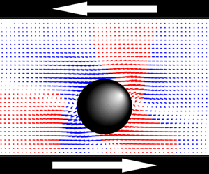
  $\theta _g={\rm \pi} /2$ correspond to a horizontally and vertically aligned channel, respectively. Figure 1 depicts the flow problem.

Figure 1. A sphere in two-dimensional shear flow between parallel walls. The behaviour of the sphere is determined by the initial transverse position  $\tilde {y}_0=y_0/H$, the confinement ratio
  $\kappa =a/H$ and the particle Reynolds number
  ${\textit {Re}}_p=Ga^2/\nu$, where
  $G=2U_m/H$. Here,
  $\theta _g$ is the angle of the imposed gravitational force
  $F_g$ in the shear plane relative to the direction of the shear gradient. The walls are infinite in the
  $x$- and
  $z$-directions.
We non-dimensionalize the problem by normalizing the position and time by the channel height and the inverse velocity gradient, respectively, such that  $\tilde {y}=y/H$ and
  $\tilde {t}=Gt$. The inertial lift force and gravitational force are normalized by
  $\rho U_m^2 a^4 / H^2$, which is the inertial force scaling at small
  ${\textit {Re}}_p$ found by Ho & Leal (Reference Ho and Leal1974). Thus, the dynamics of the sphere is dictated by the particle shear Reynolds number
  ${\textit {Re}}_p=Ga^2/\nu$, the confinement ratio
  $\kappa =a/H$, the initial position
  $\tilde {y}_0$ and the gravitational force
  $\tilde {F}_g$ applied at angle
  $\theta _g$ relative to the ambient shear gradient. Here, the tilde denotes the dimensionless counterpart of the appropriate dimensional variable, e.g.
  $\tilde {F}_g=F_g/(\rho U_m^2 a^4 / H^2)$.
The dynamics of the sphere will be quantified through two types of calculations. First, the position of the sphere will be fixed in the  $y$-direction and allowed to freely rotate and translate in the
  $x$- and
  $z$-directions. The force acting on the sphere is then calculated to determine the lift force
  $\tilde {F}_L$ at a given transverse position, which, by symmetry, is directed along the
  $y$-axis. In the second type of calculation, the sphere is force and torque free and thus allowed to rotate and translate in all directions. The position of the particle is calculated to generate particle trajectories in time and position (axial and transverse).
The effect of inertia on a neutrally buoyant sphere in confined shear flow is quantified by examining the impact of  ${\textit {Re}}_p$ and
  $\kappa$ on its equilibrium position. The lift force on the sphere at a given
  ${\textit {Re}}_p$ and
  $\kappa$ is determined at various transverse positions, spanning the channel. Zero crossings of the lift force reveal transverse equilibrium positions, with positive-to-negative crossings (i.e. a switch from a positive lift force to negative as the transverse position increase) corresponding to stable equilibria and negative-to-positive corresponding to unstable equilibria. By repeating this process over a variety of
  ${\textit {Re}}_p$, an inertial bifurcation of the equilibrium position shall be revealed above a critical
  ${\textit {Re}}_p$ dependent on
  $\kappa$. Trajectory calculations at the same
  ${\textit {Re}}_p$ will show the long-time stable equilibrium position of the sphere, thereby confirming the inertial bifurcations previously observed. Our lift force calculations will be performed at various
  $\kappa$ to reveal the impact of particle size on the critical
  ${\textit {Re}}_p$. Mikulencak & Morris (Reference Mikulencak and Morris2004) observed that velocity field about a force- and torque-free sphere in confined shear flow at the centre of the channel becomes unsteady flow above
  ${\textit {Re}}_p=100$ for
  $\kappa =0.125$; all flows in this study were below
  ${\textit {Re}}_p=100$ and no unsteady flow was observed about the sphere. Inertial migration in such unsteady flows is certainly interesting but outside the scope of the present work.
The behaviour of a non-neutrally buoyant sphere in confined shear flow will be studied in horizontally and vertically aligned channels. For horizontally aligned channels, the gravitational force  $\tilde {F}_g$ is applied on the sphere at an angle of
  $\theta _g=0$, and the trajectory of the sphere calculated in time. The resulting equilibrium positions of the sphere will be compared to predictions developed from the lift force calculations for a neutrally buoyant sphere, by subtracting the applied gravitational force from the positional lift forces to generate a new zero crossing. For a vertically aligned channel,
  $\tilde {F}_g$ is applied at an angle
  $\theta _g={\rm \pi} /2$, generating a ‘slip’ velocity for the particle relative to the streamline passing through its centre. This produces a Saffman-like lift, which will shift the equilibrium position of the sphere toward the bounding wall translating in the opposite direction to
  $\tilde {F}_g$, as demonstrated by calculations of the particle trajectory.
Finally, the dynamics of a neutrally buoyant sphere in time-dependent shear will be investigated by allowing the sphere to reach an equilibrium position, after which the flow conditions change. The impact of flow cessation will be studied by reducing the channel wall velocity from  $U_m$ to zero over a finite period and calculating the resulting trajectory of the sphere. Similarly, the effect of flow reversal is to be investigated by reversing the wall velocity from
  $U_m$ to
  $-U_m$ over a period and calculating the resulting trajectory of the sphere. The effect of duration of the change in flow on the particle dynamics will be elucidated.
3. Lattice Boltzmann calculations
The dynamics of a sphere in confined shear flow is quantified using the lattice Boltzmann (LB) method, a computational technique for solving the Navier–Stokes equations (Ladd Reference Ladd1994a,Reference Laddb; Aidun, Lu & Ding Reference Aidun, Lu and Ding1998). The method works by discretizing the fluid into a series of Eulerian nodes, where, at position  $\boldsymbol {x}$ and time
  $t$, there exists a distribution of fluid particles
  $f_{\sigma i} ( \boldsymbol {x}, t )$ with velocity
  $\boldsymbol {e}_{\sigma i}$ in the
  $\sigma i$ direction. The macroscopic fluid properties of mass density
  $\rho (\boldsymbol {x},t)$ and velocity
  $\boldsymbol {u}( \boldsymbol {x},t)$ are obtained from
 \begin{equation} \rho \left( \boldsymbol{x},t \right) = \sum_{\sigma i}\, f_{\sigma i} \left( \boldsymbol{x}, t \right) \quad \text{and} \quad \rho \left( \boldsymbol{x},t \right) \boldsymbol{u} \left( \boldsymbol{x},t \right) = \sum_{\sigma i}\, f_{\sigma i} \left( \boldsymbol{x}, t \right) \boldsymbol{e}_{\sigma i}. \end{equation}
The fluid particles obey by the dimensionless LB equation (Wu & Aidun Reference Wu and Aidun2010),
 \begin{equation} f_{\sigma i} \left( \boldsymbol{x}+\boldsymbol{e}_{\sigma i}, t+1 \right) -\,f_{\sigma i} \left( \boldsymbol{x}, t \right) ={-} \frac{1}{\tau} \left[ \,f_{\sigma i} \left( \boldsymbol{x}, t \right) - \,f_{\sigma i}^{(eq)} \left( \boldsymbol{x}, t \right) \right]+\boldsymbol{g}_{\sigma i} \left( \boldsymbol{x}, t \right), \end{equation}
dictating the time evolution of the fluid in the channel. The LB method models the fluid particle motion through alternating steps of collision and translation. Fluid particle collision, denoted by the first term on the right-hand side of (3.2), describes the interaction of the fluid particles at a given node by comparing the current distribution of particles,  $f_{\sigma i} (\boldsymbol {x}, t )$, to the equilibrium distribution of the same macroscopic velocity,
  $f_{\sigma i}^{(eq)} ( \boldsymbol {x}, t )$, over a relaxation time
  $\tau =(6\nu +1)/2$. Fluid particle translation, denoted by the first term on left side of (3.2), describes the movement of fluid particles between adjacent nodes. The final term in (3.2),
  $\boldsymbol {g}_{\sigma i} ( \boldsymbol {x}, t )$, represents forcing due to the fluid–solid interaction force (Wu & Aidun Reference Wu and Aidun2010), describing the force acting on the fluid due to the solid particle and a corresponding force acting on the nodes at the surface of the solid particle by the surrounding fluid particles. The LB equation has been shown to reduce to the Navier–Stokes equations at small Mach and Knudsen numbers (McNamara & Zanetti Reference McNamara and Zanetti1988; Chen, Chen & Mathhaeus Reference Chen, Chen and Mathhaeus1992; Huo et al. Reference Huo, Zou, Chen, Doolen and Cogley1995), and has been shown to accurately model the transient particle dynamics (Rosen et al. Reference Rosen, Do-Quang, Aidun and Lundell2015a).
An in-house LB code has been constructed to study the present problem, building from our previous work on migration of a circular cylinder. The fluid field is discretized into a computational domain of  $n_x \times n_y \times n_z$, where
  $n_i$ is the number of nodes in the
  $i$-direction, with a channel aspect ratio of
  $AR=n_x/n_y=n_x/n_z=2$. A standard bounce-back boundary condition is used to simulate the translating bounding walls (Aidun et al. Reference Aidun, Lu and Ding1998), and a periodic boundary condition is used on the open ends in the
  $y$- and
  $z$-directions. The particle is modelled by arranging a series of Lagrangian nodes over its surface using a geodesic placement algorithm (Miura & Kimoto Reference Miura and Kimoto2005), detailed further in figure 2. The net force
  $\boldsymbol {F}$ and torque
  $\boldsymbol {T}$ acting on the particle is calculated using an external boundary force (EBF) method (Wu & Aidun Reference Wu and Aidun2010), which calculates the aforementioned fluid–solid interaction force. The particle translational velocity,
  $\boldsymbol {U}_{\boldsymbol {p}}$, and particle angular velocity,
  $\boldsymbol {\varOmega }_{\boldsymbol {p}}$, are calculated from Newton's equations of rigid body motion, which for a sphere are simply
 \begin{equation} M \frac{\textrm{d} \boldsymbol{U}_{\boldsymbol{p}}(t)}{\textrm{d}t}=\boldsymbol{F}(t), \quad \text{and} \quad I \frac{\textrm{d} \boldsymbol{\varOmega}_{\boldsymbol{p}} (t)}{\textrm{d}t}=\boldsymbol{T}(t), \end{equation}
where  $M$ is the mass of the sphere and
  $I$ is its moment of inertia.

Figure 2. A depiction of the geodesic placement algorithm. The algorithm begins by inscribing an icosahedron (a) with the boundaries of the particle, such that the nodes of the polyhedron rest on the particle's surface. The edges of the polyhedron are bisected (b), producing a series of vertices. The new vertices are then projected onto the surface of the particle (c), creating additional nodes. The process is repeated until sufficient nodes exist.
The LB method is an iterative process, starting from a quiescent fluid and initiating with the bounding walls translating at a given velocity. The EBF method determines the force acting on the fluid and particle boundary nodes about the solid particle, from which a net force and torque acting on the particle can be determined through integration over the particle surface. The particle is then translated and rotated by the resulting particle velocity and angular velocities. The fluid particles then undergo collision and propagation, as previously described, and the process iterates. This cycle continues until the force acting on the particle remains constant in the fixed transverse position studies, or the particle reaches a constant  $\tilde {y}$ in the unconstrained studies.
The accuracy of our computational technique is assessed by performing three validation studies. The first considered the sedimentation of a sphere along the centreline of a bounded square channel under gravity, and the sedimentation velocity of the sphere is calculated as a function of  $\kappa$ at
  $0.1 \leqslant {\textit {Re}}_p \leqslant 0.8$, relative to the sedimentation velocity of an unbounded sphere at
  ${\textit {Re}}_p=0$,
  $U_g=F_g/6{\rm \pi} \mu a$, where
  ${\textit {Re}}_p=U_g a/\nu$,
  $\kappa =a/H$ and
  $H$ is width of the channel cross-section (figure 3a). The relative sedimentation velocity matches well to results from Wu & Aidun (Reference Wu and Aidun2010), who also used the LB method. The second validation study investigated the rotation of a neutrally buoyant sphere at the centre of a channel in confined shear flow at
  $\kappa =0.2$ as a function of
  ${\textit {Re}}_p$ (figure 3b). Our results are compared to experiments by Poe & Acrivos (Reference Poe and Acrivos1975) and simulation results by Nirschl, Dwyer & Denk (Reference Nirschl, Dwyer and Denk1995) and Mikulencak & Morris (Reference Mikulencak and Morris2004). Our calculations were found to compare favourably with these previous studies. The final validation study examined the migration of a neutrally buoyant sphere in confined shear flow at small
  ${\textit {Re}}_p$ and
  $\kappa$ (figure 3c,d); here, our results are compared to the perturbation theory of Ho & Leal (Reference Ho and Leal1974). Here, it is important to note that their theory is asymptotically valid when
  $Re_p\ll \kappa ^2\ll 1$. It is computationally prohibitive for us to run our code at such small values of
  $\kappa$ and
  $Re_p$ to recover quantitative agreement with their theory. Nonetheless, in combination, figures 3(c) and 3(d) show that our computations approach to Ho and Leal's theory as
  ${\textit {Re}}_p$ and
  $\kappa$ are separately decreased, as required. In summary, the validations detailed in figure 3 give confidence on the performance of the LB code used to generate new results that are discussed next. Further verification of our code with respect to domain size, channel periodicity, and time resolution can be found in the Appendix.

Figure 3. Validation of the in-house LB code. (a) Sedimentation velocity  $U_w$ of a confined sphere in a square channel as a function of confinement ratio
  $\kappa$, relative to the sedimentation velocity of an unbounded sphere
  $U_g$. (b) Rotation rate
  $\varOmega /G$ of a sphere in confined shear flow (
 $\kappa =0.2$ and
  $\tilde {y}_0=0$) as a function of particle Reynolds number
  ${\textit {Re}}_p$. (c) Transverse trajectory of a sphere of
  $\kappa =0.2$ and
  $\tilde {y}_0=-0.25$ in confined shear flow as a function of time at various particle Reynolds numbers
  ${\textit {Re}}_p$. (d) Transverse trajectory of a sphere of
  ${\textit {Re}}_p=1$ and
  $\tilde {y}_0=-0.4$ in confined shear flow as a function of time at various confinement ratios
  $\kappa$. Relevant results were digitized for replotting here.
4. Neutrally buoyant sphere in confined shear flow
4.1. Lift force on a transversely fixed sphere
The hydrodynamic lift force on a neutrally buoyant sphere of  $\kappa =0.2$ is calculated here. The sphere is at fixed transverse position,
  $\tilde {y}_0$, and allowed to freely rotate and translate in the direction of flow. This process is used to calculate the lift force acting on the sphere throughout the channel at various
  ${\textit {Re}}_p$, and the results are shown in figure 4. At
  ${\textit {Re}}_p=1$ the force varies monotonically across the channel, with a single zero crossing at the centre of the channel,
  $\tilde {y}=0$, corresponding to a single stable equilibrium position for the sphere. This behaviour is in qualitative agreement with Ho & Leal (Reference Ho and Leal1974). At
  ${\textit {Re}}_p=3$, the force at every fixed position (
 $\tilde {y}_0$) has decreased in magnitude, with again a monotonic variation across the channel and a single zero crossing, and therefore stable equilibrium position, at the centre of the channel. In contrast, at
  ${\textit {Re}}_p=10$, the lift force no longer varies monotonically across the channel. The lift force now possesses three zero crossings, with one at the centre of the channel and two equidistant from the centre at
  $y \simeq -0.15$ and
  $y \simeq 0.15$. Now, the centreline zero crossing corresponds to an unstable equilibrium position, while the off-centre zero crossings represent new stable equilibria; the positive-to-negative zero crossing implies a stable equilibrium position, while the opposite implies an unstable one. A supercritical pitchfork bifurcation of the equilibrium position has therefore occurred between
  $3<{\textit {Re}}_p<10$. By increasing the Reynolds number to
  ${\textit {Re}}_p=30$, the stable equilibria move closer to the walls at
  $\tilde {y} \simeq -0.21$ and
  $0.21$. At
  ${\textit {Re}}_p=50$, the stable equilibrium shifts closer to the confining walls at
  $\tilde {y} \simeq -0.24$ and
  $\simeq 0.24$.

Figure 4. Dimensionless lift force  $\tilde {F}_L$ on a sphere of
  $\kappa =0.2$ as a function of transverse position, with magnification of the lift force just below the centre of the channel in the inset. The finite particle radius precludes the centre of the particle from entering the size excluded region.
For any fixed position  $\tilde {y}$, the magnitude of the lift force decreases with increasing
  ${\textit {Re}}_p$, resulting in flatter curves at higher
  ${\textit {Re}}_p$. The decrease in force is caused by ‘inertial screening’ of the velocity disturbance caused by the particle. That is, as
  ${\textit {Re}}_p$ increases, the velocity disturbance is confined closer to the surface of the particle, screening out hydrodynamic interactions between the sphere and the wall, and thus decreasing the overall lift force. The novel aspect of these curves is the off-centre zero crossings beyond a critical
  ${\textit {Re}}_p$, changing the centre equilibrium position from stable to unstable and introducing two new stable equilibria. As demonstrated by Asmolov (Reference Asmolov1999), a neutrally buoyant sphere in shear flow bounded by a single wall experiences no equilibrium position, as the lift force is always directed away from the wall. We previously showed that the equilibrium position of a circular cylinder in confined shear flow experienced a similar inertial bifurcation as a result of the second confining wall (Fox et al. Reference Fox, Schneider and Khair2020). Our present findings indicate that this phenomenon persists in three-dimensional confined shear flows. As such, an inertial bifurcation of equilibrium positions can potentially be verified experimentally and thus may have practical relevance for particle separations.
To further examine the stable equilibria, the streamlines about spheres at their stable equilibrium positions for  ${\textit {Re}}_p=1$ and
  $10$ are shown in figure 5; the flows are shown in the shear plane. Additionally, the disturbance flows about the sphere, found by subtracting the ambient flow from the total flow, are presented in this figure. At
  ${\textit {Re}}_p=1$, the sphere rests at an equilibrium position at the centre of the channel and the flow about the particle is roughly top–down symmetric with respect to the centre of the sphere. At
  ${\textit {Re}}_p=10$, the equilibrium position of the sphere is off centre, and the flow about the sphere is no longer top–down symmetric. This asymmetry, while expected due to the position of the particle, surprisingly produces no net hydrodynamic lift on the sphere at this off-centre equilibrium position. The disturbance flow about the sphere at
  ${\textit {Re}}_p=1$ resembles that computed by Mikulencak & Morris (Reference Mikulencak and Morris2004), as in both studies the sphere is at the centre of the channel, with slightly askew recirculating flows adjacent to the sphere in the
  $\tilde {x}$-direction. Specifically, the disturbance flow takes on a quadrupolar character, as indicated by the colour shading in figures 5(c) and 5(d), which highlights that the freely suspended sphere acts as a quadrupolar source of vorticity by virtue of the no-slip condition at its surface. The disturbance flow at
  ${\textit {Re}}_p=10$, while containing recirculating flows seen by Mikulencak & Morris (Reference Mikulencak and Morris2004), differs qualitatively due to the sphere in our study lying on the off-centre equilibrium position. In particular, the top–down symmetry of the quadrupolar disturbance seen at
  ${\textit {Re}}_p=1$ is absent.

Figure 5. Streamlines for flow around spheres of  $\kappa =0.2$ at stable equilibrium positions in confined simple shear at (a)
  ${\textit {Re}}_p=1$ and (b)
  ${\textit {Re}}_p=10$, as well as velocity vectors for disturbance flow around the aforementioned spheres at (c)
  ${\textit {Re}}_p=1$ and (d)
  ${\textit {Re}}_p=10$, with flow in the positive
  $y$-direction in red and flow in the negative
  $y$-direction in blue.
Lift force calculations are repeated for confinement ratios  $\kappa =0.1$ and
  $0.15$, and the equilibrium positions at increasing
  ${\textit {Re}}_p$ are shown in figure 6. In this figure, the computations for
  $\kappa =0.2$ correspond to the equilibrium positions previously discussed, where the bifurcation occurs in the range
  $3<{\textit {Re}}_p<10$. When the confinement ratio is decreased to
  $\kappa =0.15$ and
  $0.1$, the critical
  ${\textit {Re}}_p$ required to induce the bifurcation decreases as well, occurring at
  $1<{\textit {Re}}_p<3$ and
  $0.3<{\textit {Re}}_p<1$, respectively. It is important to note that for
  $\kappa =0.1$, although the critical
  ${\textit {Re}}_p$ is smaller than unity, the critical channel Reynolds number
  ${\textit {Re}}_c={\textit {Re}}_p/\kappa ^2$ is not small (in the range
  $30<{\textit {Re}}_p<100$), and so the bifurcation occurs due to significant inertial forces on the scale of the channel flow. The theoretical results of Ho & Leal (Reference Ho and Leal1974), as well as experimental results of Halow & Willis (Reference Halow and Willis1970b,Reference Halow and Willisa), examining neutrally buoyant spheres in shear flow, do not demonstrate an inertial bifurcation of the equilibrium position as they pertain to
  ${\textit {Re}}_c \ll 1$, where the entire flow is viscous dominated.

Figure 6. Equilibrium position of a sphere in confined shear flow as a function of (a) particle Reynolds number  ${\textit {Re}}_p$ and (b) channel Reynolds number
  ${\textit {Re}}_c$, for three confinement ratios.
4.2. Migration of a freely suspended sphere
The trajectory of a neutrally buoyant sphere of  $\kappa =0.2$ is computed in confined shear flow. The sphere is located at initial positions
  $\tilde {y}_0=-0.25$ and
  $-0.1$ and allowed to freely rotate and translate until it reached an equilibrium position in the
  $y$-direction. The process was repeated for various
  ${\textit {Re}}_p$, and the results are shown in figure 7. At
  ${\textit {Re}}_p=1$, the particle translates to an equilibrium position at the centre of the channel,
  $\tilde {y}=0$. The equilibrium is independent of initial position, confirming the previous observation of a single zero crossing at
  $\tilde {y}=0$ in figure 4. At
  ${\textit {Re}}_p=3$, the equilibrium position remains at the centre of the channel, independent of the initial position. At
  ${\textit {Re}}_p=10$, the particle translates to a stable off-centre position of
  $\tilde {y} \simeq \pm 0.15$; thus, a bifurcation of the equilibrium position has occurred for
  $3<{\textit {Re}}_p<10$. The initial position of the particle now dictates the equilibrium position of the particle; spheres with initial positions of
  $\tilde {y}_0<0$ and
  $\tilde {y}_0>0$ will translate to equilibrium positions of
  $\tilde {y} \simeq -0.15$ and
  $\tilde {y} \simeq 0.15$, respectively, while a particle with an initial position of
  $\tilde {y}_0=0$ will remain at the centre in an unstable equilibrium position. At
  ${\textit {Re}}_p$=30, the equilibrium position shifts further from the channel centreline to
  $\tilde {y} \simeq \pm 0.21$. These findings are entirely consistent with those presented in § 4.1.

Figure 7. Trajectory of a freely suspended sphere of  $\kappa =0.2$ at various particle Reynolds numbers
  ${\textit {Re}}_p$, showing the change in transverse position
  $\tilde {y}$ as a function of time. A sphere with initial position
  $\tilde {y}>0$ would follow the trajectory of those shown here, mirrored about the centreline.
5. Non-neutrally buoyant sphere in confined shear flow
5.1. Migration in a horizontally aligned channel
The trajectory of a sphere of  $\kappa =0.2$ and density
  $\rho _p=2\rho$ in confined shear flow with
  ${\textit {Re}}_p=1$ and
  ${\textit {Re}}_p=10$ in a horizontally aligned channel under gravitational force
  $\tilde {F}_g$ is computed. The sphere is located at an initial position of
  $\tilde {y}_0=-0.25$,
  $-0.1$ or
  $0.1$ and allowed to freely rotate and translate until it reaches an equilibrium position. The resulting equilibrium position is compared to a prediction generated from our study of a neutrally buoyant particle in the previous section. To do so, the applied gravitational force is first linearly combined with the calculated hydrodynamic lift on a neutrally buoyant particle. This generates a new force–position curve with a new zero crossing; this zero crossing provides an approximation of the stable equilibrium position for a non-neutrally buoyant particle. The results of this exercise are shown in figure 8. The equilibrium position is found to change at all applied gravitational forces studied. Note, for
  $\tilde {F}_g=0$, the equilibrium positions would be
  $\tilde {y}=0$ and
  $\tilde {y} \simeq \pm 0.15$, respectively, as
  ${\textit {Re}}_p=1$ is below the critical
  ${\textit {Re}}_p$ for the pitchfork bifurcation and
  ${\textit {Re}}_p=10$ is above.

Figure 8. Trajectory of a sphere of  $\kappa =0.2$ at (a)
  ${\textit {Re}}_p=1$ and (b)
  ${\textit {Re}}_p=10$ under gravity in a horizontally aligned channel as a function of time. The angle of the imposed gravitational force is
  $\theta _g=0$. The dashed line corresponds to the approximated equilibrium position calculated from the lift force plot in figure 3, by linearly combining
  $\tilde {F}_g$ with the lift force
  $\tilde {F}_L$ for a neutrally buoyant particle.
At  ${\textit {Re}}_p=1$, the equilibrium position moves toward the lower confining wall, in the direction of the applied gravitational force, with only a single equilibrium position observed. The initial position was not found to impact the final equilibrium position; however, the rate at which the sphere approached the equilibrium position was affected. The sphere with an initial position of
  $\tilde {y}=0.1$ translates the most rapidly, as both the inertial lift force and applied gravitational force are affecting the particle in the same direction. Spheres with an initial position
  $\tilde {y}_0=-0.25$ translate across streamlines more rapidly than those that begin at
  $\tilde {y}_0=-0.1$. Particles closer to the bounding wall experience a greater lift force due to the positional dependence of the lift force, as shown in § 4.1. Thus, the resulting translational velocity of spheres closer to the wall will be higher.
At  ${\textit {Re}}_p=10$, the equilibrium position always shifts toward the low confining wall in the direction of gravity, but the trajectory of the particle depends on the magnitude of the force applied. For a gravitational force of
  $\tilde {F}_g=0.25$, there is an imperfect bifurcation of the equilibrium position, as the applied force is insufficient to oppose the inertial lift force directing the particle upwards. Here, by ‘imperfect’ bifurcation we mean that two stable equilibrium positions are no longer equidistant from the centre of the channel, and the equilibrium position of the sphere depends on the initial position. At
  $\tilde {F}_g=0.5$, the applied force is greater in magnitude than the local inertial force maximum, overcoming the inertial force and allowing the particle to cross the channel centre. Thus, the pitchfork equilibrium position bifurcation is broken by a sufficiently strong gravitational force, and only a single off-centre equilibrium position remains.
The results indicate that the gravitational force shifts the equilibrium position of the sphere towards the bottom bounding wall in all cases, as would be expected in a horizontally aligned channel under a uniform body force. As mentioned above, predictions of the equilibrium position of a non-neutrally buoyant sphere were created by linearly combining the calculated lift force on a neutrally buoyant particle with the applied gravitational force, thereby shifting the zero crossing and equilibrium position. This simple approximation is shown to be in reasonable agreement with the calculations in figure 8.
5.2. Migration in a vertically aligned channel
The trajectory of a sphere of  $\kappa =0.2$ and density
  $\rho _p=2\rho$ in confined shear flow with
  ${\textit {Re}}_p=1$ and
  ${\textit {Re}}_p=10$ in a vertically aligned channel under gravitational force
  $\tilde {F}_g$ is computed. The sphere is located at an initial position of
  $\tilde {y}_0=-0.25, -0.1$ or
  $0.1$ and allowed to freely rotate and translate until it reached an equilibrium position. The results are shown in figure 9. Note, for
  $\tilde {F}_g=0$, the equilibrium positions would be
  $\tilde {y}=0$ and
  $\tilde {y} \simeq \pm 0.15$, respectively, as
  ${\textit {Re}}_p=1$ is below the critical
  ${\textit {Re}}_p$ for the pitchfork bifurcation and
  ${\textit {Re}}_p=10$ is above.

Figure 9. Trajectory of a sphere of  $\kappa =0.2$ under gravity in a vertically aligned channel as a function of time for (a)
  ${\textit {Re}}_p=1$ and (b)
  ${\textit {Re}}_p=10$, as well as velocity vectors for disturbance flow around the aforementioned spheres at (c)
  ${\textit {Re}}_p=1$ with
  $\tilde {F}_g=100$ and (d)
  ${\textit {Re}}_p=10$ with
  $\tilde {F}_g=2$, with flow in the positive
  $y$-direction in red and flow in the negative
  $y$-direction in blue. The angle of the imposed gravitational force is
  $\theta _g={\rm \pi} /2$.
The results show that the applied force, in the direction of flow, causes the transverse equilibrium position of the sphere to shift toward the oppositely moving confining wall. The applied force induces a difference between the particle velocity and the fluid velocity of the streamline passing through its centre, referred to as a ‘slip velocity’. This induces a Saffman-like lift due to the relative velocity gradient across the particle, and forces the particle toward the bounding wall translating in the opposite direction of gravity. As we have noted in previous sections, while  ${\textit {Re}}_p=1$ and
  $10$ are relatively small,
  ${\textit {Re}}_c={\textit {Re}}_p/\kappa ^2=100$ and
  $1000$ are not, and as such an inertia-dominated ‘outer’ region is within the channel; as such, a Saffman-type lift is produced.
At  ${\textit {Re}}_p=1$, the equilibrium position moves toward the confining wall translating in the opposite direction to the applied gravitational force, with only a single equilibrium position observed. A greater gravitational force is required to produce an equilibrium position shift on the scale observed in § 5.1, with
  $\tilde {F}_g=100$ shifting the equilibrium position in a vertically aligned channel to a similar distance as
  $\tilde {F}_g=8$ in a horizontally aligned channel.
At  ${\textit {Re}}_p=10$, the equilibrium position again shifts toward the confining wall translating in the opposite direction to the gravitational force, but the behaviour of the sphere depends on the magnitude of the applied force. At
  $\tilde {F}_g=1$, there are still two equilibrium positions, although they are no longer equidistant from the centre; again, an imperfect bifurcation arises from the broken symmetry due to the applied force. Under this gravitational force, the induced Saffman-type lift is less than the wall-induced inertial lift force, and as such can only shift the equilibrium position. An imperfect bifurcation of the equilibrium positions occurs, with the equilibrium position of the sphere depends on its initial position. At
  $\tilde {F}_g=2$, the induced Saffman-type lift is greater in magnitude than the local wall-induced inertial lift maximum, forcing the particle across the channel centre. As such, under this gravitational force, only a single equilibrium position exists and the pitchfork equilibrium position bifurcation for a neutrally buoyant particle is broken.
The disturbance flow about the spheres allows for the visualization of the impact of the gravitational force. As seen in figure 9(c), the disturbance flow at  ${\textit {Re}}_p=1$ retains the quadrupolar characteristic seen in figure 5(c), although the symmetry of the flow has been broken due to the off-centre equilibrium position of the sphere. In figure 9(d), the disturbance flow at
  ${\textit {Re}}_p=10$ remains qualitatively similar to that seen in figure 5(d), as the equilibrium position was already off centre. Neither case shows a dipolar disturbance flow, as would be expected for a sphere settling in quiescent fluid under gravity, as the particle velocity under the gravitational force is less than the characteristic velocity of the ambient shear flow.
6. Neutrally buoyant sphere in time-dependent shear flow
6.1. Migration after flow cessation
The trajectory and rotation rate of a sphere of  $\kappa =0.2$ in confined shear flow following a cessation of the flow is computed. The sphere is located at an initial position of
  $\tilde {y}_0=-0.1$ and allowed to freely rotate and translate until it reached a centreline equilibrium position at
  ${\textit {Re}}_p=1$ or off-centre equilibrium position at
  ${\textit {Re}}_p=10$. Here, the values of
  ${\textit {Re}}_p$ pertain to the flow before cessation. Prior to flow cessation, the simulation runs for an equilibration time of
  $\tilde {t}_{EQ}=200$ under steady flow, allowing the sphere to reach an equilibrium position within the channel. After equilibrating, the velocity of the confining wall is decreased from
  $U_m$ to zero, with
  $U_m$ dictated by the Reynolds number of the specific computation, over a period of
  $\Delta \tilde {t}$. The sphere is allowed to freely translate and rotate in the slowing fluid until it reaches a final equilibrium position. The results of this study are shown in figure 10. At
  ${\textit {Re}}_p=1$, the particle remains at the centre of the channel and does not move laterally during flow cessation. At
  ${\textit {Re}}_p=10$, the cessation of the flow induces particle motion away from its initial off-centre equilibrium position. For
  $\Delta \tilde {t} \leqslant 10$, the effect of flow cessation is similar, with the sphere shifting toward the centreline, reaching a final equilibrium position of
  $\tilde {y} \simeq -0.12$. The parametric plot indicates that particle motion ultimately ceases in the
  $x$- and
  $y$-directions, with only slight drift of the particle in the
  $x$-direction following flow cessation. For
  $\Delta \tilde {t} \geqslant 30$, the equilibrium position shifted closer to the centre of the channel, reaching final equilibrium positions of
  $\tilde {y} \simeq -0.11$ and
  $-0.07$ at
  $\Delta \tilde {t}$ of
  $30$ and
  $100$, respectively. At
  $\Delta \tilde {t}=1000$, the particle translates to the centre of the channel, reaching a final equilibrium position at
  $\tilde {y}=0$. These behaviours were confirmed to be independent of relaxation time,
  $\tau$.

Figure 10. Trajectory of a sphere of  $\kappa =0.2$ under cessation of shear flow (a) as a function of time and (b) as a function of distance in the flow direction. At
  $\tilde {t}=200$, denoted in (a) by a dashed line vertical and in (b) by a black circle, the velocity of the bounding walls of the channel decreases from
  $U_m$ to 0 over a period of
  $\Delta \tilde {t}$. The relative rotation rate of a sphere
  $\tilde {\varOmega }/\tilde {\varOmega }_{max}$ following the cessation of the channel walls as a function of (c) time and (d) relative shear gradient.
At all transition times probed, the rotation rate of the sphere at  ${\textit {Re}}_p=1$ slowed faster than a sphere at
  ${\textit {Re}}_p=10$, due to the greater inertia in the latter case, shown in figure 10(c). The slowing of rotation of the sphere is dictated by two time scales: a time scale of the dissipation of momentum across the channel,
  $H^2/\nu$, and a time scale for the ceasing of the channel walls,
  $\Delta \tilde {t}$. As shown in figure 10(d), at
  $\Delta \tilde {t}=3$, the particle continues rotating after the relative shear gradient goes to zero, as the momentum dissipates on a slower time scale than the channel walls come to a halt, or cease. As the transition time increases, the rotation of the particle when the walls cease lowers, as more momentum is able to dissipate. By
  $\Delta \tilde {t}=300$, the momentum dissipation time scale is much less than the flow ceasing time scale, and as such, the rotation of the particle ceases when the channel walls cease translating.
The shift of the particle toward the centre of the channel during cessation is the result of the particle experiencing instantaneously smaller  ${\textit {Re}}_p$ as the flow ceases. During the period of cessation, the particle experiences non-zero,
  ${\textit {Re}}_p$ flows, as the instantaneous
  ${\textit {Re}}_p$ in the channel drops from
  $10$ to
  $0$. These flows produce equilibrium positions closer to and eventually at the centre of the channel, driving the particle inward. The greater shift toward the centre with increasing
  $\Delta \tilde {t}$ is caused by the particle sampling lower
  ${\textit {Re}}_p$ flows for longer times. Above
  $\Delta \tilde {t} \geqslant 30$, this effect becomes more pronounced, leading to greater changes in equilibrium position, as well as extended drift in the direction of flow. At
  $\Delta \tilde {t} = 1000$, the sphere reaches the centre of the channel, as the sphere experiences flows below the critical
  ${\textit {Re}}_p$ for enough time to allow the inertial lift to drive the particle to a central equilibrium position. This result is noteworthy, as a finite stopping time can be explored further through experimentation. Using a rheometer, Couette flow can be generated in a laboratory setting and, by varying the rate at which the shearing ceases, the behaviour of particles as detailed in this section could be confirmed.
6.2. Migration after flow reversal
The trajectory of a sphere of  $\kappa =0.2$ in confined shear flow following a reversal of the flow is computed. The sphere is located at an initial position of
  $\tilde {y}_0=-0.1$ and allowed to freely rotate and translate until it reached a centreline equilibrium position at
  ${\textit {Re}}_p=1$ or and off-centre equilibrium position at
  ${\textit {Re}}_p=10$ of
  $\tilde {y} \simeq -0.15$. Prior to flow reversal, the simulation runs for an equilibration time of
  $\tilde {t}_{EQ}=200$ under steady flow, allowing the sphere to reach an equilibrium position within the channel. After equilibrating, the velocities of the confining walls are reversed from
  $U_m$ to
  $-U_m$ and from
  $-U_m$ to
  $U_m$, with
  $U_m$ dictated by the Reynolds number of the specific computation, over a period of
  $\Delta \tilde {t}$. The results of this study are shown in figure 11. At
  ${\textit {Re}}_p=1$, the particle remains at the centre of the channel and does not move during flow reversal. At
  ${\textit {Re}}_p=10$, the reversal of the flow induces particle motion away from its equilibrium position before the flow reverses. That is, the sphere translates towards the centre of the channel, before reversing direction and returning to its original equilibrium position at
  $\tilde {y} \simeq -0.15$. The period of reversal does not affect the long time behaviour of the sphere, although longer reversal times above
  $\Delta \tilde {t} \geqslant 30$ cause the sphere to translate closer to the centre of the channel and require a longer time to return to the equilibrium position. These behaviours were confirmed to be independent of relaxation time,
  $\tau$.

Figure 11. Trajectory of a sphere of  $\kappa =0.2$ in reversing shear flow (a) as a function of time and (b) as a function of distance in the flow direction. At
  $\tilde {t}=200$, denoted in (a) by a dashed line and in (b) by a black circle, the velocity of the bounding walls of channel reverses from
  $U_m$ to
  $-U_m$ over a period of
  $\Delta \tilde {t}$. The relative rotation rate of a sphere
  $\tilde {\varOmega }-\tilde {\varOmega }_{min}/\tilde {\varOmega }_{max}-\tilde {\varOmega }_{min}$ following the cessation of the channel walls as a function of (c) time and (d) relative shear gradient.
The rotation rate of the sphere at  ${\textit {Re}}_p=1$ decelerated faster than a sphere at
  ${\textit {Re}}_p=10$ for all transition times tested, shown in figure 11(c), as the latter flow contained more inertia than the former. Similar to § 6.1, the reversing of rotation of the sphere is dictated by two time scales: a momentum dissipation time scale and channel wall translation reversing time scale. As shown in figure 11(d), at
  $\Delta \tilde {t}=3$, the particle rotation continues reversing after the shear gradient reversed, as the momentum dissipates on a slower time scale than the channel walls reverse. As the transition time increases, the rotation of the particle is closer to reversed when the channel walls reverse translation, as more momentum is able to dissipate. At
  $\Delta \tilde {t}=300$, the momentum dissipation time scale is much less than the flow reversing time scale, and as such, the rotation of the particle is fully reversed when the channel walls reverse translation direction. That is, here the rotation responds quasi-steadily with the changing wall velocity.
As in the case of flow cessation in § 6.1, the translation of the particle toward the channel centre is caused by the sphere experiencing instantaneously smaller  ${\textit {Re}}_p$ as the flow reverses. During flow reversal, the instantaneous
  ${\textit {Re}}_p$ in the channel drops from
  $10$ to
  $0$, before increasing again to
  $10$. The equilibrium positions created by these flows are closer to or at the centre of the channel, resulting in the particle moving toward the centre before
  ${\textit {Re}}_p$ returns to
  $10$. Above
  $\Delta \tilde {t} \geqslant 30$, the cross-streamline translation occurs for a greater time, as the sphere samples lower
  ${\textit {Re}}_p$ for greater times and shifts the position closer toward the centre. At
  $\Delta \tilde {t}=1000$, the sphere nearly reaches the centre of the channel, as the flow remains subcritical (i.e. the instantaneous
  ${\textit {Re}}_p$ is below the critical
  ${\textit {Re}}_p$ for equilibrium position bifurcation) for enough time to allow the inertial lift to drive the sphere toward very near the centre. Similarly to the previous section, the examination of finite reversal times is of particular interest for examination through physical experimentation. Likewise, such a system could be analysed using a Couette flow rheometer in oscillatory shear, allowing for experimental confirmation of particle trajectories after flow reversal, although the curved streamlines in Couette flow could alter the trajectories from what is computed here.
7. Conclusions
In this study, the dynamics of a rigid sphere in confined shear flow was quantified via the LB method. The equilibrium position of a neutrally buoyant sphere in confined shear is predicted to undergo a supercritical pitchfork bifurcation above a critical  ${\textit {Re}}_p$, which is below the transition to unsteady flow. Below the critical
  ${\textit {Re}}_p$, the sphere has a single stable equilibrium position located at the centre of the channel, while above the critical
  ${\textit {Re}}_p$, the sphere has three possible equilibria. The aforementioned centre equilibrium position remains, but becomes unstable, and two new stable equilibrium positions exist equidistant from the centre of the channel. The critical
  ${\textit {Re}}_p$ was shown to increase with
  $\kappa$ and, therefore, particle size.
A non-neutrally buoyant sphere in confined shear flow was shown to migrate to new equilibrium positions dependent on the magnitude of the gravitational force acting upon it. In horizontally aligned channels, the gravitational force on the sphere acts transverse to the direction of flow and shifts the equilibrium position of the sphere toward the lower confining wall. In the regime tested, this gravitational force and the inertial force on a neutrally buoyant particle could be linearly combined to produce a reasonable prediction of the equilibrium position of a non-neutrally buoyant particle. In a vertically aligned channel, the gravitational force on the sphere acts in the direction of flow, creating a slip velocity between the particle and shear flow. This induces a Saffman-like lift force that was shown to shift the equilibrium of the particle toward the oppositely moving bounding wall. In both channel alignments, when the flow is above the critical  ${\textit {Re}}_p$, there exists a gravitational force range such that the equilibrium position bifurcation persists, but no longer exhibits the symmetric pitchfork characteristic seen for a neutrally buoyant particle. When gravitational force is sufficiently strong enough, this bifurcation breaks and only a single off-centre equilibrium position remains.
The dynamics of a neutrally buoyant sphere in time-dependent confined shear flow was shown to depend on the period of variation of the flow. Following a cessation of the flow, a sphere with an off-centre equilibrium was seen to shift towards the centre of the channel, while particles at the centre remained stationary in the transverse position. The amount of translation toward the centre was shown to depend on the period over which the confining walls of the channel stopped, with longer transition periods resulting in equilibrium positions closer to the centre. In the case of flow reversal, the equilibrium position of a sphere was seen to remain at its initial position; however, a sphere with an equilibrium position off centre will undergo a translational period during which it will move toward, then away from, the centre of the channel. The distance the particle translates toward the centre increases with longer transition times, as does the time over which the translation of the particle occurs.
As the equilibrium bifurcation occurs at non-zero  ${\textit {Re}}_p$, the particle contributes to the bulk stress in a suspension (i.e. particles plus fluid) through both the stresslet on its surface and an acceleration stress (Batchelor Reference Batchelor1970). The latter effect resembles a Reynolds stress and is due to variations in the velocity field around the particle relative to the mean flow in the suspension. The stresslet on a sphere in confined shear flow at the centre of a channel has been computed by Mikulencak & Morris (Reference Mikulencak and Morris2004) to vary with the Reynolds number, as the flow about the sphere changes with
  ${\textit {Re}}_p$. In future studies of the bifurcation uncovered in the present work, the effect of the change in equilibrium position on the stresslet could be investigated. Specifically, calculating the stresslet as the equilibrium position bifurcates could reveal a signature change beyond the critical
  ${\textit {Re}}_p$. Additionally, the acceleration stress could be calculated both below and above the critical
  ${\textit {Re}}_p$.
Our observation of a bifurcation in equilibrium position for spheres suggests future work should examine the generality of this phenomenon. Specifically, the behaviour of anisotropic particles, such as oblate and prolate spheroids, in confined inertial flows would be of particular interest. In unbounded shear flow, neutrally buoyant spheroids undergo a range of rotational dynamics, such as Jeffery orbits at  ${\textit {Re}}_p=0$ (Jeffery Reference Jeffery1922) and tumbling and rolling states at finite
  ${\textit {Re}}_p$ for prolate and oblate spheroids, respectively (Mao & Alexeev Reference Mao and Alexeev2014; Rosen, Lundell & Aidun Reference Rosen, Lundell and Aidun2014; Rosen et al. Reference Rosen, Einarsson, Nordmark, Aidun, Lundell and Mehlig2015b). The addition of this rotational dynamics would create an additional translational dynamics unseen in our study of spheres, which undergo simple rotation. Notably, the study of the inertial dynamics of spheres and spheroids could be verified through laboratory experimentation. Using a parallel band apparatus, a flow cell could be constructed that creates a planar shear flow about both neutrally and non-neutrally buoyant particles (Taylor Reference Taylor1934; Rust & Manga Reference Rust and Manga2002). Confirmation of the dynamics of particles in inertial flow, as well the equilibrium position bifurcation observed in this study, would represent the first step toward developing novel particle separation devices. Such an apparatus could offer separations of high selectivity, as the dynamics of the particles would change abruptly above a critical
  ${\textit {Re}}_p$, due to the equilibrium position bifurcation.
Funding
This work was supported by a graduate fellowship from the PPG Foundation to A.J.F. and by a grant from the Pennsylvania Infrastructure Technology Alliance supplied by the Pennsylvania Department of Community and Economic Development.
Declaration of interests
The authors report no conflict of interest.
Appendix. Further verification of LB computations
It is important to ensure that the computational parameters, such as the domain size, the channel periodicity and time resolution, do not impact the conclusions of our work. The convergence of our computations with respect to the values of these parameters will be addressed here by examining the translation and equilibrium position of a neutrally buoyant sphere in confined shear flow of  $\kappa =0.2$.
The size of the computational domain directly affects the resolution of the simulations. To minimize the errors, the computational domain should be made as large as possible; however, excessively large domains are too computationally expensive. As such, it is necessary to determine the minimum domain size necessary to produce results that are invariant with increasing the domain size. To study the domain size dependence, the trajectory of a neutrally buoyant sphere with  $\kappa =0.2$ at
  $Re_p=1$ and
  $Re_p=10$ is considered. Three different computational domain sizes of
  $AR=N_x/N_y=2$ are tested, at
  $(N_x,N_y,N_z)=(64,32,32)$,
  $(96,48,48)$, and
  $(128,64,64)$. The shear rate was held constant at
  $G=1/1000$, thus removing the influence of time resolution from the study. It is seen in figure 12 that the trajectory for the sphere in all cases remains independent of the domain size. As the computation time did not prove prohibitively large and to ensure maximum veracity, a domain of
  $(128,64,64)$ was used for the results reported in the main text of this article.

Figure 12. Trajectory of a sphere of  $\kappa =0.2$ at
  $Re_p=1$ and
  $Re_p=10$ at three different domain sizes,
  $nx \times ny \times nz$, where
  $ny=nz=0.5nx$.
The periodicity of the computational domain can alter the dynamics of simulated particles. As the simulation uses a periodic boundary condition in the direction of flow, there is essentially an infinite array of simultaneously translating particles in the  $x$-direction. If the aspect ratio of the channel
  $AR=N_x/N_y$ is too small, the flow about the sphere will be influenced by the flow about the neighbouring virtual particles. It is necessary to select an
  $AR$ such that the dynamics of the particle simulated is independent of the virtual particles, while remaining small enough to not induce excessive computational times. To study the periodicity, three different channel aspect ratios are tested of
  $AR=2$, 3, and 4. The shear rate was again held constant at
  $G=1/1000$. It is shown in figure 13 that the trajectory for the sphere in all cases remains independent of the domain size, with all spheres migrating to the centre of the channel along the same path. To reduce computational time, an aspect ratio of
  $AR=2$ is used for the results reported in the main text.

Figure 13. Trajectory of a sphere of  $\kappa =0.2$ at
  $Re_p=1$ at three different channel aspect ratios,
  $AR=nx/ny$.
Last, we turn to the time resolution of the simulations. The time resolution is inversely dependent on the shear rate  $G$, as high shear rates, and therefore characteristic velocities, produce high Mach number flows, which the derivation of the LB equation and thus LB computations require to be small. However, lower shear gradients lead to longer computational times, which may be prohibitively expensive. Therefore, the ideal shear gradient is the largest
  $G$ such that the reduction of
  $G$ does not alter the dynamics of the simulation. To study the time resolution dependence, the trajectory of a neutrally buoyant sphere in confined shear flow is considered at three different shear gradients
  $G=1/1000$, 1/2000 and 1/3000. It is shown in figure 14 that the trajectory for the sphere in all cases remains independent of the domain size, with all spheres migrating to the centre of the channel along the same path. To reduce computational time, a shear gradient of
  $G=1/1000$ is used for the results reported in the main text.

Figure 14. Trajectory of a sphere of  $\kappa =0.2$ at
  $Re_p=1$ at three different shear rates,
  $G$.
$G$.


