


1. Introduction
1.1. Background
Shallow-water flow of a homogeneous fluid over bottom topography is a fundamental problem in fluid mechanics and has been heavily studied from various points of view. A widely used approach when the topography is a single localised obstacle is the application of hydraulic concepts which lead to the classification of the flow in terms of the value of the upstream Froude number, defined as the ratio of the uniform upstream flow to the linear long-wave speed. The flow is then described as supercritical, subcritical or transcritical depending on whether the upstream Froude number is greater than unity, less than unity, or close to unity, respectively; see for instance the monograph by Baines (Reference Baines1995) for a comprehensive account of hydraulic theory and the issues involved. In the supercritical case, waves generated by the flow interaction with the obstacle propagate downstream away from the obstacle, and the flow at the obstacle location is a locally steady elevation. In the subcritical case, waves propagate upstream and downstream away from the obstacle, and the flow at the obstacle location is a locally steady depression. When wave dispersion is considered, steady lee waves are also formed downstream of the obstacle. Both these cases can be well understood, at least qualitatively, using linearised theory.
However, linearised theory fails in the transcritical regime, which is the main interest here, and then a nonlinear theory is needed to describe the locally steady hydraulic flow over the obstacle, which has an upstream elevation and a downstream depression, each terminated by upstream- and downstream-propagating undular bores. A popular model here in the weakly nonlinear regime when the obstacle has a small amplitude is the forced Korteweg–de Vries (KdV) equation; see Akylas (Reference Akylas1984), Cole (Reference Cole1985), Grimshaw & Smyth (Reference Grimshaw and Smyth1986), Lee, Yates & Wu (Reference Lee, Yates and Wu1989), Binder, Dias & Vanden-Broeck (Reference Binder, Dias and Vanden-Broeck2006), Grimshaw, Zhang & Chow (Reference Grimshaw, Zhang and Chow2007) and the recent review by Grimshaw (Reference Grimshaw2010). Various aspects of the extension to finite amplitudes in the long-wave regime can be found in El, Grimshaw & Smyth (Reference El, Grimshaw and Smyth2006, Reference El, Grimshaw and Smyth2008, Reference El, Grimshaw and Smyth2009).
Thus transcritical shallow-water flow is quite well understood for a single localised obstacle, but there have been comparatively very few studies of the analogous case when there are two widely separated localised obstacles. In the context of this paper, the most relevant is the article by Pratt (Reference Pratt1984), where a combination of steady hydraulic theory, numerical simulations using the nonlinear shallow-water equations and laboratory experiments are used to infer that the formation of dispersive waves between the obstacles is needed to obtain a stable solution. More recently Dias & Vanden-Broeck (Reference Dias and Vanden-Broeck2004) and Ee et al. (Reference Ee, Grimshaw, Zhang and Chow2010, Reference Ee, Grimshaw, Chow and Zhang2011) have examined the possible presence of such waves for steady flows, while Grimshaw, Zhang & Chow (Reference Grimshaw, Zhang and Chow2009) considered the related problem of unsteady flow over a wide hole. Thus a new feature of interest when considering two obstacles is that the waves generated by each obstacle may interact in the region between them, and then the question is how this interaction might affect the long-time outcome. In this paper we examine this scenario using the nonlinear shallow-water equations, so that, although finite-amplitude effects are included, wave dispersion is neglected and the generated waves are represented as shock waves. Our emphasis is on the transcritical regime for two widely spaced localised obstacles. The nonlinear shallow-water equations are solved numerically using a well-balanced finite-volume method, and the results are shown in § 3. The simulations are supplemented by a combination of fully nonlinear hydraulic theory with classical shock closure conditions, and a reduced model used in the weakly nonlinear regime, presented in § 2. We conclude in § 4.
1.2. Formulation
The basic model is one-dimensional shallow-water flow past topography, in which the flow is described by the total local depth
 $H$
and the depth-averaged horizontal velocity
$H$
and the depth-averaged horizontal velocity
 $U$
. The upstream flow is a constant horizontal velocity
$U$
. The upstream flow is a constant horizontal velocity
 $V>0$
, and the forcing is due to a localised topographic obstacle
$V>0$
, and the forcing is due to a localised topographic obstacle
 $f(x)$
so that the bottom is at
$f(x)$
so that the bottom is at
 $z=-h+f(x)$
, where
$z=-h+f(x)$
, where
 $h$
is the undisturbed depth at infinity. Henceforth, we use non-dimensional coordinates, based on a length scale
$h$
is the undisturbed depth at infinity. Henceforth, we use non-dimensional coordinates, based on a length scale
 $h$
, a velocity scale
$h$
, a velocity scale
 $\sqrt{gh}$
and a time scale of
$\sqrt{gh}$
and a time scale of
 $\sqrt{h/g}$
, in terms of which the equation system is
$\sqrt{h/g}$
, in terms of which the equation system is
 $$\begin{eqnarray}{\it\zeta}_{t}+(HU)_{x}=0,\quad H=1+{\it\zeta}-f,\end{eqnarray}$$
 $$\begin{eqnarray}U_{t}+UU_{x}+{\it\zeta}_{x}=0.\end{eqnarray}$$
In these non-dimensional coordinates, the constant upstream flow is
 $\mathit{Fr}=V/\sqrt{gh}$
, the Froude number. Here the topography
$\mathit{Fr}=V/\sqrt{gh}$
, the Froude number. Here the topography
 $f(x)$
consists of two obstacles, each symmetrical, and placed a distance
$f(x)$
consists of two obstacles, each symmetrical, and placed a distance
 $L$
apart, with respective maximum heights (or depths) of
$L$
apart, with respective maximum heights (or depths) of
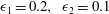
 ${\it\epsilon}_{1,2}$
. Our interest here is when
${\it\epsilon}_{1,2}$
. Our interest here is when
 ${\it\epsilon}_{1,2}>0$
, and the situation when either or both
${\it\epsilon}_{1,2}>0$
, and the situation when either or both
 ${\it\epsilon}_{1,2}<0$
will be considered elsewhere. We assume that the separation distance
${\it\epsilon}_{1,2}<0$
will be considered elsewhere. We assume that the separation distance
 $L$
is much greater than the width of the obstacles. Then the main parameters are the Froude number Fr, and the maximum heights
$L$
is much greater than the width of the obstacles. Then the main parameters are the Froude number Fr, and the maximum heights
 ${\it\epsilon}_{1,2}$
. This system is to be solved with the initial conditions
${\it\epsilon}_{1,2}$
. This system is to be solved with the initial conditions
 $$\begin{eqnarray}H=1,\quad U=\mathit{Fr},\quad \text{at}~t=0.\end{eqnarray}$$
This is equivalent to introducing the obstacles instantaneously at
 $t=0$
into a constant flow. The solution will initially develop smoothly, but, being a nonlinear hyperbolic system, we can expect the development of discontinuities in the derivatives of
$t=0$
into a constant flow. The solution will initially develop smoothly, but, being a nonlinear hyperbolic system, we can expect the development of discontinuities in the derivatives of
 ${\it\zeta}$
and
${\it\zeta}$
and
 $U$
. The classical procedure is then to introduce shocks, given by
$U$
. The classical procedure is then to introduce shocks, given by
 $$\begin{eqnarray}-S[{\it\zeta}]+[HU]=0,\quad -S[HU]+[HU^{2}+{\textstyle \frac{1}{2}}H^{2}]=0.\end{eqnarray}$$
Here
 $S$
is the shock speed, and
$S$
is the shock speed, and
 $[\cdots \,]$
denotes the jump across the shock. In the absence of the bumps (
$[\cdots \,]$
denotes the jump across the shock. In the absence of the bumps (
 $f(x)=0$
), these classical shocks conserve mass and momentum.
$f(x)=0$
), these classical shocks conserve mass and momentum.
In the transcritical regime when
 $\mathit{Fr}\approx 1$
, it will be useful also to consider a weakly nonlinear model for small-amplitude topography, given by
$\mathit{Fr}\approx 1$
, it will be useful also to consider a weakly nonlinear model for small-amplitude topography, given by
 $$\begin{eqnarray}-{\it\zeta}_{t}-{\it\Delta}{\it\zeta}_{x}+{\textstyle \frac{3}{2}}{\it\zeta}{\it\zeta}_{x}+{\textstyle \frac{1}{2}}\,f_{x}=0,\quad {\it\Delta}=\mathit{Fr}-1.\end{eqnarray}$$
Here
 $U=\mathit{Fr}+u$
and
$U=\mathit{Fr}+u$
and
 $u\approx -{\it\zeta}$
. The reduced model (1.5) can be seen as a dispersionless forced KdV equation; see the aforementioned references. For convenience, we present an alternative derivation in appendix A. The initial condition (1.3) is replaced by
$u\approx -{\it\zeta}$
. The reduced model (1.5) can be seen as a dispersionless forced KdV equation; see the aforementioned references. For convenience, we present an alternative derivation in appendix A. The initial condition (1.3) is replaced by
 $$\begin{eqnarray}{\it\zeta}=0,\quad \text{at}~t=0.\end{eqnarray}$$
In this weakly nonlinear limit, the shock conditions (1.4) reduce to
 $$\begin{eqnarray}(S-{\it\Delta})[{\it\zeta}]+{\textstyle \frac{3}{4}}[{\it\zeta}^{2}]=0.\end{eqnarray}$$
This can also of course be directly deduced from (1.5).

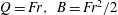
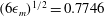
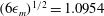
Figure 1. Plot of (2.3) at equality. The intersections of the line
 ${\it\epsilon}_{m}=\text{const.}$
with the curve (2.3) define
${\it\epsilon}_{m}=\text{const.}$
with the curve (2.3) define
 $\mathit{Fr}_{b,p}$
, respectively. The region below the curve defines the subcritical and supercritical regimes, and the region above the curve is the transcritical regime.
$\mathit{Fr}_{b,p}$
, respectively. The region below the curve defines the subcritical and supercritical regimes, and the region above the curve is the transcritical regime.
2. Hydraulic flow
2.1. Steady solutions
Here we consider the hydraulic theory, and to begin with we review the well-known theory (see e.g. Baines Reference Baines1995) for flow over a single obstacle. Then we will show how this can be extended to obtain analogous solutions for flow over two obstacles. Thus we seek steady solutions, so that, on omitting the time derivatives, (1.1) and (1.2) integrate to
 $$\begin{eqnarray}HU=(1+{\it\zeta}-f)U=Q,\quad {\it\zeta}+{\textstyle \frac{1}{2}}U^{2}=B.\end{eqnarray}$$
Here
 $Q$
and
$Q$
and
 $B$
are positive integration constants, representing mass flux and energy flux, respectively (strictly,
$B$
are positive integration constants, representing mass flux and energy flux, respectively (strictly,
 $Q$
is volume flux, but we are assuming that the fluid density has been scaled to unity; and
$Q$
is volume flux, but we are assuming that the fluid density has been scaled to unity; and
 $B$
is the Bernoulli constant, while
$B$
is the Bernoulli constant, while
 $BQ$
is the energy flux). Eliminating
$BQ$
is the energy flux). Eliminating
 $H$
or
$H$
or
 $U$
gives
$U$
gives
 $$\begin{eqnarray}\frac{G^{4/3}}{2}+\frac{1}{G^{2/3}}=\frac{B+1-f}{Q^{2/3}},\quad G=\frac{U}{H^{1/2}}=\frac{U^{3/2}}{Q^{1/2}}=\frac{Q}{H^{3/2}},\end{eqnarray}$$
which determines the local Froude number
 $G$
as a function of the obstacle height
$G$
as a function of the obstacle height
 $f$
.
$f$
.
For non-critical flow, this solution must connect smoothly to
 $U=\mathit{Fr},~{\it\zeta}=0$
, that is,
$U=\mathit{Fr},~{\it\zeta}=0$
, that is,
 $G=\mathit{Fr}$
, at infinity, and so
$G=\mathit{Fr}$
, at infinity, and so
 $Q=\mathit{Fr},~B=\mathit{Fr}^{2}/2$
. Noting that then the right-hand side of the first expression in (2.2) has a minimum value of
$Q=\mathit{Fr},~B=\mathit{Fr}^{2}/2$
. Noting that then the right-hand side of the first expression in (2.2) has a minimum value of
 $3/2-{\it\epsilon}_{m}$
when
$3/2-{\it\epsilon}_{m}$
when
 $\mathit{Fr}=1$
, it can be established that
$\mathit{Fr}=1$
, it can be established that
 $$\begin{eqnarray}0<{\it\epsilon}_{m}<1+\frac{\mathit{Fr}^{2}}{2}-\frac{3\mathit{Fr}^{2/3}}{2}.\end{eqnarray}$$
Here
 ${\it\epsilon}_{m}$
is the maximum obstacle height. This expression is plotted in figure 1 at equality (note that this is the curve BAE in figure 2.11 of Baines (Reference Baines1995)). It defines the subcritical regime
${\it\epsilon}_{m}$
is the maximum obstacle height. This expression is plotted in figure 1 at equality (note that this is the curve BAE in figure 2.11 of Baines (Reference Baines1995)). It defines the subcritical regime
 $\mathit{Fr}<\mathit{Fr}_{b}<1$
where
$\mathit{Fr}<\mathit{Fr}_{b}<1$
where
 $\mathit{Fr}<G<1$
, and the supercritical regime
$\mathit{Fr}<G<1$
, and the supercritical regime
 $1<\mathit{Fr}_{p}<\mathit{Fr}$
where
$1<\mathit{Fr}_{p}<\mathit{Fr}$
where
 $1<G<\mathit{Fr}$
and a smooth steady hydraulic solution exists. In the subcritical regime a localised depression forms over the obstacle, and in the supercritical regime a localised elevation forms over the obstacle. For small
$1<G<\mathit{Fr}$
and a smooth steady hydraulic solution exists. In the subcritical regime a localised depression forms over the obstacle, and in the supercritical regime a localised elevation forms over the obstacle. For small
 $({\it\epsilon}_{m})^{1/2}\ll 1$
, recalling that
$({\it\epsilon}_{m})^{1/2}\ll 1$
, recalling that
 ${\it\Delta}=\mathit{Fr}-1$
, we find that
${\it\Delta}=\mathit{Fr}-1$
, we find that
 $$\begin{eqnarray}{\it\Delta}_{p,b}=\pm \frac{(6{\it\epsilon}_{m})^{1/2}}{2}+\frac{{\it\epsilon}_{m}}{4}+O\left({\it\epsilon}_{m}^{3/2}\right).\end{eqnarray}$$
In the transcritical regime
 $\mathit{Fr}_{b}<\mathit{Fr}<\mathit{Fr}_{p}$
, (2.3) does not hold and is replaced by
$\mathit{Fr}_{b}<\mathit{Fr}<\mathit{Fr}_{p}$
, (2.3) does not hold and is replaced by
 $$\begin{eqnarray}{\it\epsilon}_{m}>1+\frac{\mathit{Fr}^{2}}{2}-\frac{3\mathit{Fr}^{2/3}}{2}.\end{eqnarray}$$
Instead, we seek a solution which has upstream and downstream shocks propagating away from the obstacle, and which satisfies the critical flow condition at the top of the obstacle, that is, when
 $f={\it\epsilon}_{m}$
,
$f={\it\epsilon}_{m}$
,
 $G_{x}\neq 0$
. This condition implies that
$G_{x}\neq 0$
. This condition implies that
 $$\begin{eqnarray}G=1,\quad \frac{3Q^{2/3}}{2}=B+1-{\it\epsilon}_{m}\quad \text{at}~f={\it\epsilon}_{m}.\end{eqnarray}$$
For a given
 ${\it\epsilon}_{m}$
, this relation defines
${\it\epsilon}_{m}$
, this relation defines
 $B$
in terms of
$B$
in terms of
 $Q$
. At this critical location,
$Q$
. At this critical location,
 $U=U_{m}=Q^{1/3}$
and
$U=U_{m}=Q^{1/3}$
and
 $1+{\it\zeta}_{m}-{\it\epsilon}_{m}=Q^{2/3}$
. The local Froude number varies over the range
$1+{\it\zeta}_{m}-{\it\epsilon}_{m}=Q^{2/3}$
. The local Froude number varies over the range
 $G_{-}<G<G_{+}$
, where
$G_{-}<G<G_{+}$
, where
 $+$
and
$+$
and
 $-$
denote the downstream and upstream values, respectively. It transpires that, in order for the shocks to propagate away from the obstacle, the flow is subcritical upstream where
$-$
denote the downstream and upstream values, respectively. It transpires that, in order for the shocks to propagate away from the obstacle, the flow is subcritical upstream where
 $G_{-}<G<1$
,
$G_{-}<G<1$
,
 ${\it\zeta}_{-}>{\it\zeta}>{\it\zeta}_{m}$
,
${\it\zeta}_{-}>{\it\zeta}>{\it\zeta}_{m}$
,
 $U_{-}<U<U_{m}$
, and supercritical downstream where
$U_{-}<U<U_{m}$
, and supercritical downstream where
 $1<G<G_{+}$
,
$1<G<G_{+}$
,
 ${\it\zeta}_{+}<{\it\zeta}<{\it\zeta}_{m}$
,
${\it\zeta}_{+}<{\it\zeta}<{\it\zeta}_{m}$
,
 $U_{+}>U>U_{m}$
.
$U_{+}>U>U_{m}$
.

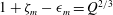
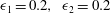
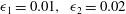
Figure 2. Schematic for closure using classical shocks.
Before proceeding, we note that the expressions (2.2) hold both upstream and downstream, yielding the relationships
 $$\begin{eqnarray}U_{\pm }(1+{\it\zeta}_{\pm })^{1/2}=Q,\quad \frac{U_{\pm }^{2}}{2}+{\it\zeta}_{\pm }=B,\end{eqnarray}$$
and so
 $$\begin{eqnarray}\displaystyle & \displaystyle \frac{U_{\pm }^{2}}{2}+\frac{Q}{U_{\pm }}=\frac{Q^{2}}{2(1+{\it\zeta}_{\pm })^{2}}+{\it\zeta}_{\pm }+1=B+1, & \displaystyle\end{eqnarray}$$
 $$\begin{eqnarray}\displaystyle & \displaystyle \frac{G_{\pm }^{4/3}}{2}+\frac{1}{G_{\pm }^{2/3}}=\frac{B+1}{Q^{2/3}}. & \displaystyle\end{eqnarray}$$
 $Q$
and
$Q$
and
 $B$
, these relations fix
$B$
, these relations fix
 $U_{\pm }$
and
$U_{\pm }$
and
 ${\it\zeta}_{\pm }$
completely. But we have one relationship (2.6) connecting
${\it\zeta}_{\pm }$
completely. But we have one relationship (2.6) connecting
 $B$
and
$B$
and
 $Q$
, and so there is just a single constant to determine. This is found using the classical shock closure described in the next section.
$Q$
, and so there is just a single constant to determine. This is found using the classical shock closure described in the next section.
2.2. Classical shock closure
Outside the obstacle,
 $U=U_{\pm }$
and
$U=U_{\pm }$
and
 ${\it\zeta}={\it\zeta}_{\pm }$
are constants, downstream and upstream, respectively, and are connected to the undisturbed values
${\it\zeta}={\it\zeta}_{\pm }$
are constants, downstream and upstream, respectively, and are connected to the undisturbed values
 $U=\mathit{Fr}$
and
$U=\mathit{Fr}$
and
 ${\it\zeta}=0$
far downstream and upstream, using classical shock closure based on the shock conditions (1.4); see figure 2. Since the steady hydraulic flow over the obstacle conserves mass and energy, rather than mass and momentum, these are non-trivial conditions to apply. Further, it transpires that we cannot simultaneously impose upstream and downstream jumps which connect directly to the uniform flow. Instead, we first impose an upstream jump as specified by Baines (Reference Baines1995); see also El et al. (Reference El, Grimshaw and Smyth2009). There is then a downstream jump which connects to a rarefaction wave; see figure 2.
${\it\zeta}=0$
far downstream and upstream, using classical shock closure based on the shock conditions (1.4); see figure 2. Since the steady hydraulic flow over the obstacle conserves mass and energy, rather than mass and momentum, these are non-trivial conditions to apply. Further, it transpires that we cannot simultaneously impose upstream and downstream jumps which connect directly to the uniform flow. Instead, we first impose an upstream jump as specified by Baines (Reference Baines1995); see also El et al. (Reference El, Grimshaw and Smyth2009). There is then a downstream jump which connects to a rarefaction wave; see figure 2.
First we consider the upstream jump, which connects
 ${\it\zeta}_{-},~U_{-}$
to
${\it\zeta}_{-},~U_{-}$
to
 $0,~\mathit{Fr}$
with
$0,~\mathit{Fr}$
with
 $S_{-}<0$
. The first relation in (1.4) gives
$S_{-}<0$
. The first relation in (1.4) gives
 $$\begin{eqnarray}{\it\zeta}_{-}(S_{-}-U_{-})=U_{-}-\mathit{Fr}\quad \text{or}\quad S_{-}{\it\zeta}_{-}=Q-\mathit{Fr},\end{eqnarray}$$
and the second relation in (1.4) gives
 $$\begin{eqnarray}(1+{\it\zeta}_{-})(U_{-}-\mathit{Fr})(S_{-}-U_{-})={\it\zeta}_{-}\biggl(1+\frac{{\it\zeta}_{-}}{2}\biggr).\end{eqnarray}$$
Eliminating
 $S_{-}$
, or
$S_{-}$
, or
 $U_{-}-\mathit{Fr}$
, yields the following expressions:
$U_{-}-\mathit{Fr}$
, yields the following expressions:
 $$\begin{eqnarray}\displaystyle & \displaystyle (1+{\it\zeta}_{-})(U_{-}-\mathit{Fr})^{2}={\it\zeta}_{-}^{2}\biggl(1+\frac{{\it\zeta}_{-}}{2}\biggr), & \displaystyle\end{eqnarray}$$
 $$\begin{eqnarray}\displaystyle & \displaystyle S_{-}=\mathit{Fr}-\biggl[(1+{\it\zeta}_{-})\biggl(1+\frac{{\it\zeta}_{-}}{2}\biggr)\biggr]^{1/2}, & \displaystyle\end{eqnarray}$$
 $$\begin{eqnarray}\displaystyle & \displaystyle (1+{\it\zeta}_{-})\mathit{Fr}-{\it\zeta}_{-}\biggl[(1+{\it\zeta}_{-})\biggl(1+\frac{{\it\zeta}_{-}}{2}\biggr)\biggr]^{1/2}=Q. & \displaystyle\end{eqnarray}$$
Since we need
 $S_{-}<0$
, it follows that we must have
$S_{-}<0$
, it follows that we must have
 ${\it\zeta}_{-}>0$
and
${\it\zeta}_{-}>0$
and
 $U_{-}<Q<\mathit{Fr}$
. The system of equations is now closed, as the combination of (2.8) and (2.14) determines
$U_{-}<Q<\mathit{Fr}$
. The system of equations is now closed, as the combination of (2.8) and (2.14) determines
 ${\it\zeta}_{-}$
in terms of
${\it\zeta}_{-}$
in terms of
 $B$
, so that finally all unknowns are obtained in terms of
$B$
, so that finally all unknowns are obtained in terms of
 ${\it\epsilon}_{m}$
from (2.6). Further, the condition
${\it\epsilon}_{m}$
from (2.6). Further, the condition
 ${\it\zeta}_{-}>0$
serves to define the transcritical regime (2.5) in terms of the Froude number
${\it\zeta}_{-}>0$
serves to define the transcritical regime (2.5) in terms of the Froude number
 $\mathit{Fr}$
and
$\mathit{Fr}$
and
 ${\it\epsilon}_{m}$
.
${\it\epsilon}_{m}$
.
Downstream, this procedure also determines
 $U_{+}>\mathit{Fr},~{\it\zeta}_{+}<0$
, but, in general, this cannot be resolved by a jump directly to the state
$U_{+}>\mathit{Fr},~{\it\zeta}_{+}<0$
, but, in general, this cannot be resolved by a jump directly to the state
 $\mathit{Fr},0$
. Instead we must insert a right-propagating rarefaction wave; see figure 2. The rarefaction wave propagates downstream into the undisturbed state
$\mathit{Fr},0$
. Instead we must insert a right-propagating rarefaction wave; see figure 2. The rarefaction wave propagates downstream into the undisturbed state
 $0,\mathit{Fr}$
, and so is defined by the values
$0,\mathit{Fr}$
, and so is defined by the values
 $U_{r}$
and
$U_{r}$
and
 ${\it\zeta}_{r}$
where
${\it\zeta}_{r}$
where
 $$\begin{eqnarray}U_{r}-2(1+{\it\zeta}_{r})^{1/2}=\mathit{Fr}-2.\end{eqnarray}$$
It is then connected to the hydraulic downstream state
 $U_{+},~{\it\zeta}_{+}$
by a shock, using the jump conditions (1.4) to connect the two states through a shock with speed
$U_{+},~{\it\zeta}_{+}$
by a shock, using the jump conditions (1.4) to connect the two states through a shock with speed
 $S_{+}>0$
. There are then three equations for the three unknowns
$S_{+}>0$
. There are then three equations for the three unknowns
 ${\it\zeta}_{r},~U_{r},~S_{+}$
and the system is closed.
${\it\zeta}_{r},~U_{r},~S_{+}$
and the system is closed.
In the weakly nonlinear regime, when the forcing is sufficiently small (the appropriate small parameter is
 ${\it\alpha}\sim \sqrt{{\it\epsilon}_{m}}$
), the rarefaction wave contribution can be neglected, as it has an amplitude of order
${\it\alpha}\sim \sqrt{{\it\epsilon}_{m}}$
), the rarefaction wave contribution can be neglected, as it has an amplitude of order
 ${\it\alpha}^{3}$
while the shock intensity is
${\it\alpha}^{3}$
while the shock intensity is
 $O({\it\alpha})$
. In this limit we can solve the system of equations by an expansion in
$O({\it\alpha})$
. In this limit we can solve the system of equations by an expansion in
 ${\it\alpha}$
and find that
${\it\alpha}$
and find that
 $$\begin{eqnarray}\displaystyle 3{\it\zeta}_{\pm }=2{\it\Delta}\mp (6{\it\epsilon}_{m}+{\it\beta}_{\pm })^{1/2}+O({\it\alpha}^{3}),\quad {\it\beta}_{\pm }=3{\it\zeta}_{\pm }^{3}-2{\it\zeta}_{\pm }{\it\Delta}^{2}+\frac{4{\it\Delta}^{3}}{9}, & & \displaystyle\end{eqnarray}$$
 $$\begin{eqnarray}\displaystyle & \left.\begin{array}{@{}c@{}}\displaystyle S_{\pm }={\it\Delta}-\frac{3{\it\zeta}_{\pm }}{4}+\frac{{\it\zeta}_{\pm }^{2}}{32}+O({\it\alpha}^{3}),\quad G_{\pm }=1+{\it\Delta}-\frac{3{\it\zeta}_{\pm }}{2}+{\it\gamma}_{\pm }+O({\it\alpha}^{3}),\\ \displaystyle {\it\gamma}_{\pm }=\frac{9{\it\zeta}_{\pm }^{2}}{8}-\frac{{\it\zeta}_{\pm }{\it\Delta}}{2},\end{array}\right\} & \displaystyle\end{eqnarray}$$
 $$\begin{eqnarray}\displaystyle & \displaystyle Q=1+{\it\Delta}+{\it\zeta}_{\pm }{\it\Delta}-\frac{3{\it\zeta}_{\pm }^{2}}{4}+O({\it\alpha}^{3}). & \displaystyle\end{eqnarray}$$
 ${\it\beta}_{\pm }=O({\it\alpha}^{3})$
and
${\it\beta}_{\pm }=O({\it\alpha}^{3})$
and
 ${\it\gamma}_{\pm }=O({\it\alpha}^{2})$
are small correction terms, which if needed explicitly can be evaluated to leading order using the leading-order solution for
${\it\gamma}_{\pm }=O({\it\alpha}^{2})$
are small correction terms, which if needed explicitly can be evaluated to leading order using the leading-order solution for
 ${\it\zeta}_{\pm }$
. It is useful to note here that using (2.16) and (2.4), the local Froude numbers
${\it\zeta}_{\pm }$
. It is useful to note here that using (2.16) and (2.4), the local Froude numbers  $$\begin{eqnarray}G_{\pm }=1\pm \frac{(6{\it\epsilon}_{m})^{1/2}}{2}+O({\it\alpha}^{2})=1+{\it\Delta}_{p,b}+O({\it\alpha}^{2})\end{eqnarray}$$
and are independent of
 ${\it\Delta}$
at the leading order in
${\it\Delta}$
at the leading order in
 ${\it\alpha}$
. Also, since the transcritical regime is defined by
${\it\alpha}$
. Also, since the transcritical regime is defined by
 ${\it\Delta}_{s}<{\it\Delta}<{\it\Delta}_{p}$
, it follows that, at the leading order in
${\it\Delta}_{s}<{\it\Delta}<{\it\Delta}_{p}$
, it follows that, at the leading order in
 ${\it\alpha}$
, the local downstream and upstream Froude numbers
${\it\alpha}$
, the local downstream and upstream Froude numbers
 $G_{\pm }$
are outside this transcritical regime, and hence the downstream and upstream flows are indeed fully supercritical and subcritical, respectively.
$G_{\pm }$
are outside this transcritical regime, and hence the downstream and upstream flows are indeed fully supercritical and subcritical, respectively.
2.3. Two obstacles
The same procedure can now be followed when there are two widely separated obstacles. Based on our numerical simulations reported in § 3, the solution evolves in two stages. In the first stage, the theory described above can be applied to each obstacle separately. Then in the second stage, when the downstream-propagating waves emitted by the first obstacle interact with the upstream-propagating waves emitted by the first obstacle, an interaction takes place and there is an adjustment to a new configuration. There are several scenarios depending on the obstacle heights
 ${\it\epsilon}_{1,2}$
and the Froude number
${\it\epsilon}_{1,2}$
and the Froude number
 $\mathit{Fr}$
. For instance, if both obstacles satisfy the condition (2.3) for subcritical or supercritical flow, then the solutions obtained for each obstacle separately will again be obtained. On the other hand, if both obstacles satisfy the condition (2.5) for transcritical flow, then at the end of the first stage a downstream depression shock preceded by a rarefaction wave emitted by the first obstacle will meet an upstream elevation shock emitted by the second obstacle. Our numerical simulations show that these generate a new shock between the obstacles. The speed
$\mathit{Fr}$
. For instance, if both obstacles satisfy the condition (2.3) for subcritical or supercritical flow, then the solutions obtained for each obstacle separately will again be obtained. On the other hand, if both obstacles satisfy the condition (2.5) for transcritical flow, then at the end of the first stage a downstream depression shock preceded by a rarefaction wave emitted by the first obstacle will meet an upstream elevation shock emitted by the second obstacle. Our numerical simulations show that these generate a new shock between the obstacles. The speed
 $S_{int}$
of this shock can be found from (1.4) where the conservation of mass law implies that
$S_{int}$
of this shock can be found from (1.4) where the conservation of mass law implies that
 $$\begin{eqnarray}S_{int}({\it\zeta}_{2-}-{\it\zeta}_{1+})=(1+{\it\zeta}_{2-})U_{2-}-(1+{\it\zeta}_{1+})U_{1+}+O({\it\alpha}^{3})=Q_{2}-Q_{1}+O({\it\alpha}^{3}).\end{eqnarray}$$
Here the
 $O({\it\alpha}^{3})$
error is due to the presence of the rarefaction wave. Since
$O({\it\alpha}^{3})$
error is due to the presence of the rarefaction wave. Since
 ${\it\zeta}_{2-}>0>{\it\zeta}_{1+}$
, the shock moves in the positive or negative direction depending on whether
${\it\zeta}_{2-}>0>{\it\zeta}_{1+}$
, the shock moves in the positive or negative direction depending on whether
 $Q_{2}\,>\,({<})\,Q_{1}$
. Indeed, using the expressions (2.17) and (2.14),
$Q_{2}\,>\,({<})\,Q_{1}$
. Indeed, using the expressions (2.17) and (2.14),
 $$\begin{eqnarray}S_{int}={\it\Delta}-{\textstyle \frac{3}{4}}({\it\zeta}_{1+}+{\it\zeta}_{2-})+O({\it\alpha}^{2})={\textstyle \frac{1}{4}}[(6{\it\epsilon}_{1})^{1/2}-(6{\it\epsilon}_{2})^{1/2}]+O({\it\alpha}^{2})\end{eqnarray}$$
and is independent of
 ${\it\Delta}$
to this order. Thus, this shock will move towards the higher of the two obstacles, that is,
${\it\Delta}$
to this order. Thus, this shock will move towards the higher of the two obstacles, that is,
 $S_{int}$
is positive or negative according to whether
$S_{int}$
is positive or negative according to whether
 ${\it\epsilon}_{1}>{\it\epsilon}_{2}$
or
${\it\epsilon}_{1}>{\it\epsilon}_{2}$
or
 ${\it\epsilon}_{1}<{\it\epsilon}_{2}$
, respectively. This is followed by the interaction of this shock with either the second or first obstacle, followed eventually by an adjustment to a final localised steady state encompassing both obstacles; this is the second stage.
${\it\epsilon}_{1}<{\it\epsilon}_{2}$
, respectively. This is followed by the interaction of this shock with either the second or first obstacle, followed eventually by an adjustment to a final localised steady state encompassing both obstacles; this is the second stage.
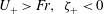
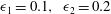
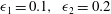
The final localised steady hydraulic state can now be determined as before, with the criterion that criticality occurs at the higher obstacle so that the formulae in §§ 2.1 and 2.2 apply with
 ${\it\epsilon}_{m}=\max [{\it\epsilon}_{1},{\it\epsilon}_{2}]$
, the same as if the combination of the two obstacles was a single obstacle. Indeed, the criticality determined at the first stage at the higher obstacle persists into the second stage, while the flow at the lower obstacle adjusts in the second stage to be locally subcritical if the lower obstacle is the first obstacle, or is locally supercritical if the lower obstacle is the second obstacle. Illustrative examples taken from the numerical simulations are shown in figures 3 and 4, respectively. Note that criticality is controlled by the higher obstacle which has the same height in the two cases, and hence the same constant values of
${\it\epsilon}_{m}=\max [{\it\epsilon}_{1},{\it\epsilon}_{2}]$
, the same as if the combination of the two obstacles was a single obstacle. Indeed, the criticality determined at the first stage at the higher obstacle persists into the second stage, while the flow at the lower obstacle adjusts in the second stage to be locally subcritical if the lower obstacle is the first obstacle, or is locally supercritical if the lower obstacle is the second obstacle. Illustrative examples taken from the numerical simulations are shown in figures 3 and 4, respectively. Note that criticality is controlled by the higher obstacle which has the same height in the two cases, and hence the same constant values of
 $Q$
and
$Q$
and
 $B$
are generated in the region containing both obstacles.
$B$
are generated in the region containing both obstacles.

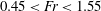
Figure 3. Hydraulic solution for the case
 $\mathit{Fr}=1$
and unequal obstacle heights
$\mathit{Fr}=1$
and unequal obstacle heights
 ${\it\epsilon}_{1}=0.1,~{\it\epsilon}_{2}=0.2$
. In the steady region over both obstacles,
${\it\epsilon}_{1}=0.1,~{\it\epsilon}_{2}=0.2$
. In the steady region over both obstacles,
 $Q=0.8923$
and
$Q=0.8923$
and
 $B=0.5900$
, and
$B=0.5900$
, and
 $G=0.6584$
at the crest of the first obstacle where the flow is locally subcritical.
$G=0.6584$
at the crest of the first obstacle where the flow is locally subcritical.

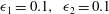
Figure 4. Hydraulic solution for the case
 $\mathit{Fr}=1$
and unequal obstacle heights
$\mathit{Fr}=1$
and unequal obstacle heights
 ${\it\epsilon}_{1}=0.2,~{\it\epsilon}_{2}=0.1$
. In the steady region over both obstacles,
${\it\epsilon}_{1}=0.2,~{\it\epsilon}_{2}=0.1$
. In the steady region over both obstacles,
 $Q=0.8923$
and
$Q=0.8923$
and
 $B=0.5900$
, and
$B=0.5900$
, and
 $G=1.463$
at the crest of the second obstacle where the flow is locally supercritical.
$G=1.463$
at the crest of the second obstacle where the flow is locally supercritical.
When the obstacles have equal heights,
 ${\it\epsilon}_{1}={\it\epsilon}_{2}$
, then also
${\it\epsilon}_{1}={\it\epsilon}_{2}$
, then also
 $Q_{1}=Q_{2}$
and the shock speed
$Q_{1}=Q_{2}$
and the shock speed
 $S_{int}=0({\it\alpha}^{3})$
, so that the error term in (2.20) is needed to determine the shock speed. This error term is due to the neglected rarefaction wave, and when this has a negative mass flux, as sketched in the scenario shown in figure 2,
$S_{int}=0({\it\alpha}^{3})$
, so that the error term in (2.20) is needed to determine the shock speed. This error term is due to the neglected rarefaction wave, and when this has a negative mass flux, as sketched in the scenario shown in figure 2,
 $S_{int}<0$
. The numerical solutions show that this is indeed the case. Hence it is then the second obstacle that controls criticality. An example taken from our numerical simulations is shown in figure 5. In the region over both obstacles combined, there is a steady state with constant values of
$S_{int}<0$
. The numerical solutions show that this is indeed the case. Hence it is then the second obstacle that controls criticality. An example taken from our numerical simulations is shown in figure 5. In the region over both obstacles combined, there is a steady state with constant values of
 $Q$
and
$Q$
and
 $B$
satisfying the relation (2.6). The local Froude number
$B$
satisfying the relation (2.6). The local Froude number
 $G=1$
at the crest of the second obstacle, where
$G=1$
at the crest of the second obstacle, where
 $G$
passes smoothly from subcritical
$G$
passes smoothly from subcritical
 $G<1$
to supercritical
$G<1$
to supercritical
 $G>1$
. The flow is subcritical over the first obstacle, but
$G>1$
. The flow is subcritical over the first obstacle, but
 $G=1$
at the crest of the first obstacle. At this location there is a discontinuity in the slope of
$G=1$
at the crest of the first obstacle. At this location there is a discontinuity in the slope of
 $G$
, and hence also in the slopes of
$G$
, and hence also in the slopes of
 $U$
and
$U$
and
 $H$
, but all quantities are continuous. This can be deduced from (2.2) and (2.6) where near the crest of either obstacle
$H$
, but all quantities are continuous. This can be deduced from (2.2) and (2.6) where near the crest of either obstacle
 $$\begin{eqnarray}(G-1)^{2}\approx \frac{3({\it\epsilon}_{m}-f)}{2Q^{2/3}}.\end{eqnarray}$$
There are two possible solutions. We consider for simplicity the generic case when
 ${\it\epsilon}_{m}-f\approx {\it\delta}(x\pm L)^{2},~{\it\delta}>0$
. Then at the second obstacle there is a smooth solution for which
${\it\epsilon}_{m}-f\approx {\it\delta}(x\pm L)^{2},~{\it\delta}>0$
. Then at the second obstacle there is a smooth solution for which
 $G-1\approx C(x-L)$
,
$G-1\approx C(x-L)$
,
 $C=\sqrt{3{\it\delta}/2Q^{2/3}}$
, but at the first obstacle the solution is
$C=\sqrt{3{\it\delta}/2Q^{2/3}}$
, but at the first obstacle the solution is
 $1-G\approx C|x+L|$
, which is continuous but has a discontinuous slope. This can be regarded as a stationary contact discontinuity. This scenario is asymmetrical and so differs from those considered by Pratt (Reference Pratt1984), who examined only symmetrical configurations and showed that these could not be stable. Further, he pointed out that it is not possible to construct a steady stable solution using a stationary shock, as this would then dissipate energy (see the last paragraph of his § 1 and footnote on p. 1216).
$1-G\approx C|x+L|$
, which is continuous but has a discontinuous slope. This can be regarded as a stationary contact discontinuity. This scenario is asymmetrical and so differs from those considered by Pratt (Reference Pratt1984), who examined only symmetrical configurations and showed that these could not be stable. Further, he pointed out that it is not possible to construct a steady stable solution using a stationary shock, as this would then dissipate energy (see the last paragraph of his § 1 and footnote on p. 1216).

Figure 5. Hydraulic solution for the case
 $\mathit{Fr}=1$
and equal obstacle heights
$\mathit{Fr}=1$
and equal obstacle heights
 ${\it\epsilon}_{1}={\it\epsilon}_{2}=0.1$
. In the steady region over both obstacles,
${\it\epsilon}_{1}={\it\epsilon}_{2}=0.1$
. In the steady region over both obstacles,
 $Q=0.9469$
and
$Q=0.9469$
and
 $B=0.5464$
, and
$B=0.5464$
, and
 $G=1$
at the crest of the first obstacle, but
$G=1$
at the crest of the first obstacle, but
 $G<1$
in the vicinity of the first obstacle where the flow is locally subcritical.
$G<1$
in the vicinity of the first obstacle where the flow is locally subcritical.
2.4. Reduced model
Before presenting the numerical results, it is useful to examine the same scenario as presented above in §§ 2.1–2.3 using the reduced model, especially as then the initial value problem can be solved (see e.g. Grimshaw & Smyth Reference Grimshaw and Smyth1986; Grimshaw Reference Grimshaw2010). With the initial condition that
 ${\it\zeta}=0$
at
${\it\zeta}=0$
at
 $t=0$
, (1.5) can be solved using characteristics,
$t=0$
, (1.5) can be solved using characteristics,
 $$\begin{eqnarray}\left.\begin{array}{@{}l@{}}\displaystyle \frac{\text{d}x}{\text{d}t}={\it\Delta}-\frac{3{\it\zeta}}{2},\quad \frac{\text{d}{\it\zeta}}{\text{d}t}=\frac{f_{x}}{2},\\ \displaystyle x=x_{0},\quad {\it\zeta}=0,\quad \text{at}~t=0.\end{array}\right\}\end{eqnarray}$$
The system (2.23) can be integrated to yield
 $$\begin{eqnarray}{\it\Delta}{\it\zeta}-\frac{3{\it\zeta}^{2}}{4}=\frac{1}{2}(f(x)-f(x_{0})),\end{eqnarray}$$
 $$\begin{eqnarray}3{\it\zeta}=2{\it\Delta}\mp {\it\Delta}\{4{\it\Delta}^{2}+6[f(x_{0})-f(x)]\}^{1/2}.\end{eqnarray}$$
 $2{\it\Delta}=3{\it\zeta}$
and then the lower sign is chosen. When
$2{\it\Delta}=3{\it\zeta}$
and then the lower sign is chosen. When
 ${\it\Delta}=0$
the upper (lower) sign is chosen on the left-hand (right-hand) side of the maximum point where
${\it\Delta}=0$
the upper (lower) sign is chosen on the left-hand (right-hand) side of the maximum point where
 $f={\it\epsilon}_{m}$
. Where characteristics intersect, a shock forms with speed
$f={\it\epsilon}_{m}$
. Where characteristics intersect, a shock forms with speed
 $S$
, given by (1.7) Then when
$S$
, given by (1.7) Then when  $$\begin{eqnarray}2{\it\Delta}^{2}<3{\it\epsilon}_{1,2}\end{eqnarray}$$
there is a critical
 $x_{0c}$
for each obstacle such that all characteristics with
$x_{0c}$
for each obstacle such that all characteristics with
 $x_{0}<x_{0c}$
have a turning point, propagate upstream and form an upstream shock. Otherwise all characteristics with
$x_{0}<x_{0c}$
have a turning point, propagate upstream and form an upstream shock. Otherwise all characteristics with
 $x_{0}>x_{0c}$
have no turning points, propagate downstream and form a downstream shock. The critical point is defined by
$x_{0}>x_{0c}$
have no turning points, propagate downstream and form a downstream shock. The critical point is defined by
 $3f(x_{0c})=3{\it\epsilon}_{1,2}-2{\it\Delta}^{2}$
. Then, in the first stage, a steady solution will emerge over each obstacle, terminated by upstream and downstream shocks, determined by that characteristic emanating from
$3f(x_{0c})=3{\it\epsilon}_{1,2}-2{\it\Delta}^{2}$
. Then, in the first stage, a steady solution will emerge over each obstacle, terminated by upstream and downstream shocks, determined by that characteristic emanating from
 $x_{0c}$
and the corresponding steady solution is found using (2.24a
),
$x_{0c}$
and the corresponding steady solution is found using (2.24a
),
 $$\begin{eqnarray}4{\it\Delta}^{2}-12{\it\Delta}{\it\zeta}+9{\it\zeta}^{2}=6({\it\epsilon}_{m}-f(x)),\end{eqnarray}$$
 $$\begin{eqnarray}3{\it\zeta}=2{\it\Delta}\mp \text{sign}[x\mp L]\{6[{\it\epsilon}_{m}-f(x)]\}^{1/2}.\end{eqnarray}$$
 ${\it\zeta}_{\mp }$
, where
${\it\zeta}_{\mp }$
, where  $$\begin{eqnarray}3{\it\zeta}_{\mp }=2{\it\Delta}\pm \{6{\it\epsilon}_{m}\}^{1/2},\end{eqnarray}$$
respectively. Note that
 ${\it\zeta}_{+}>0$
and
${\it\zeta}_{+}>0$
and
 ${\it\zeta}_{-}<0$
so that the upstream shock is elevation and the downstream shock is depression. The speeds of these shocks are found from (1.7), that is,
${\it\zeta}_{-}<0$
so that the upstream shock is elevation and the downstream shock is depression. The speeds of these shocks are found from (1.7), that is,
 $$\begin{eqnarray}4S_{\mp }=2{\it\Delta}\mp \{6{\it\epsilon}_{m}\}^{1/2}\end{eqnarray}$$
and
 $S_{-}<0,~S_{+}>0$
, while the local Froude number is
$S_{-}<0,~S_{+}>0$
, while the local Froude number is
 $$\begin{eqnarray}G=1+{\it\Delta}-3{\it\zeta}/2\quad \text{and so}\quad G_{\mp }=1\mp \frac{\{6{\it\epsilon}_{m}\}^{1/2}}{2}.\end{eqnarray}$$
In the first stage, this local steady solution holds only for each obstacle separately. When there are two obstacles, the upstream elevation shock from the obstacle will meet the downstream depression shock from the obstacle. This generates a new shock, with speed
 $$\begin{eqnarray}S_{int}={\it\Delta}-{\textstyle \frac{3}{4}}({\it\zeta}_{1+}+{\it\zeta}_{2-})={\textstyle \frac{1}{4}}[(6{\it\epsilon}_{1})^{1/2}-(6{\it\epsilon}_{2})^{1/2}],\end{eqnarray}$$
which is independent of
 ${\it\Delta}$
, and is positive or negative according to whether
${\it\Delta}$
, and is positive or negative according to whether
 ${\it\epsilon}_{1}>{\it\epsilon}_{2}$
or
${\it\epsilon}_{1}>{\it\epsilon}_{2}$
or
 ${\it\epsilon}_{1}<{\it\epsilon}_{2}$
, respectively. These results all agree with the small-amplitude limits of the corresponding expressions in the preceding subsections.
${\it\epsilon}_{1}<{\it\epsilon}_{2}$
, respectively. These results all agree with the small-amplitude limits of the corresponding expressions in the preceding subsections.
3. Numerical results
3.1. Numerical method
The nonlinear shallow-water equations (1.1) and (1.2) can be written as
 $$\begin{eqnarray}\mathscr{U}_{t}+\mathscr{F}_{x}=\mathscr{G},\end{eqnarray}$$
where
 $\mathscr{U}$
,
$\mathscr{U}$
,
 $\mathscr{F}$
and
$\mathscr{F}$
and
 $\mathscr{G}$
represent the density vector, flux vector and source term, respectively,
$\mathscr{G}$
represent the density vector, flux vector and source term, respectively,
 $$\begin{eqnarray}\mathscr{U}=\left[\begin{array}{@{}c@{}}H\\ UH\end{array}\right],\quad \mathscr{F}=\left[\begin{array}{@{}c@{}}UH\\ HU^{2}+H^{2}/2\end{array}\right],\quad \mathscr{G}=\left[\begin{array}{@{}c@{}}0\\ -Hf_{x}\end{array}\right].\end{eqnarray}$$
The computational domain,
 $0<x<x_{L}$
, is discretised by uniform cell size
$0<x<x_{L}$
, is discretised by uniform cell size
 ${\rm\Delta}x$
. The cell centre is denoted by
${\rm\Delta}x$
. The cell centre is denoted by
 $x_{i}$
, where
$x_{i}$
, where
 $x_{i-1/2}$
and
$x_{i-1/2}$
and
 $x_{i+1/2}$
refer the left and the right cell interface, respectively.
$x_{i+1/2}$
refer the left and the right cell interface, respectively.
In discretisation form, (3.1) can be written as
 $$\begin{eqnarray}\frac{\mathscr{U}_{i}^{n+1}-\mathscr{U}_{i}^{n}}{{\rm\Delta}t}+\frac{\mathscr{F}_{i+1/2}^{n}-\mathscr{F}_{i-1/2}^{n}}{{\rm\Delta}x}=\mathscr{G}_{i}^{n}.\end{eqnarray}$$
Superscript
 $n$
refers to the time-step level. The gradient of the flux function is approximated by the difference of numerical fluxes at the left,
$n$
refers to the time-step level. The gradient of the flux function is approximated by the difference of numerical fluxes at the left,
 $\mathscr{F}_{i-1/2}^{n}$
, and the right,
$\mathscr{F}_{i-1/2}^{n}$
, and the right,
 $\mathscr{F}_{i+1/2}^{n}$
, of cell interfaces, respectively. At the cell interface
$\mathscr{F}_{i+1/2}^{n}$
, of cell interfaces, respectively. At the cell interface
 $i+1/2$
,
$i+1/2$
,
 $$\begin{eqnarray}\mathscr{F}_{i+1/2}^{n}=\mathscr{F}(\mathscr{U}_{i+1/2-}^{n},\mathscr{U}_{i+1/2+}^{n}).\end{eqnarray}$$
Numerical flux at the cell interface is a function of an unknown variable on the left and the right limits, and
 $$\begin{eqnarray}\mathscr{U}_{i+1/2-}^{n}=\left[\begin{array}{@{}c@{}}H_{i+1/2-}^{n}\\ H_{i+1/2-}^{n}U_{i}^{n^{2}}\end{array}\right],\quad \mathscr{U}_{i+1/2+}^{n}=\left[\begin{array}{@{}c@{}}H_{i+1/2+}^{n}\\ H_{i+1/2+}^{n}U_{i+1}^{n^{2}}\end{array}\right].\end{eqnarray}$$
Applying the hydrostatic reconstruction from Audusse et al. (Reference Audusse, Bouchut, Bristeau, Klein and Perthame2004),
 $$\begin{eqnarray}H_{i+1/2-}^{n}=\max (0,H_{i}+f_{i}-f_{i+1/2})\quad \text{and}\quad H_{i+1/2+}^{n}=\max (0,H_{i+1}+f_{i+1}-f_{i+1/2}).\end{eqnarray}$$
Bottom slope is now included in the reconstruction of water depth. The value of bottom height at the corresponding interface is approximated by upwind evaluation,
 $$\begin{eqnarray}f_{i+1/2}=\max (f_{i},f_{i+1}).\end{eqnarray}$$
To obtain a well-balanced scheme, the gradient of source term and flux difference must be balanced at steady state (Audusse et al. Reference Audusse, Bouchut, Bristeau, Klein and Perthame2004), so (3.3) can be rewritten as
 $$\begin{eqnarray}\frac{\mathscr{U}_{i}^{n+1}-\mathscr{U}_{i}^{n}}{{\rm\Delta}t}+\frac{\mathscr{F}_{l}^{n}(\mathscr{U}_{i}^{n},\mathscr{U}_{i+1}^{n},f_{i},f_{i+1})-\mathscr{F}_{r}^{n}(\mathscr{U}_{i-1}^{n},\mathscr{U}_{i}^{n},f_{i-1},f_{i})}{{\rm\Delta}x}=0,\end{eqnarray}$$
with modified numerical fluxes
 $$\begin{eqnarray}\displaystyle & \displaystyle \mathscr{F}_{l}^{n}(\mathscr{U}_{i}^{n},\mathscr{U}_{i+1}^{n},f_{i},f_{i+1})=\mathscr{F}(\mathscr{U}_{i+1/2-}^{n},\mathscr{U}_{i+1/2+}^{n})+[0,H_{i}^{n^{2}}-H_{i+1/2-}^{n^{2}}]/2, & \displaystyle\end{eqnarray}$$
 $$\begin{eqnarray}\displaystyle & \displaystyle \mathscr{F}_{r}^{n}(\mathscr{U}_{i}^{n},\mathscr{U}_{i+1}^{n},f_{i},f_{i+1})=\mathscr{F}(\mathscr{U}_{i+1/2-}^{n},\mathscr{U}_{i+1/2+}^{n})+[0,H_{i+1}^{n^{2}}-H_{i+1/2+}^{n^{2}}]/2. & \displaystyle\end{eqnarray}$$
 $\mathscr{F}(\mathscr{U}_{i+1/2-}^{n},\mathscr{U}_{i+1/2+}^{n})$
. We also apply the minmod flux limiter based on the total variation diminishing (TVD) proposed by Toro (Reference Toro1992) in our numerical scheme to remove spurious oscillations when simulating the moving shock problem.
$\mathscr{F}(\mathscr{U}_{i+1/2-}^{n},\mathscr{U}_{i+1/2+}^{n})$
. We also apply the minmod flux limiter based on the total variation diminishing (TVD) proposed by Toro (Reference Toro1992) in our numerical scheme to remove spurious oscillations when simulating the moving shock problem.
In our simulations, we apply transmissive boundaries to allow waves to propagate outwards on both boundaries. The bottom elevation is assumed to be two Gaussian obstacles given by
 $$\begin{eqnarray}f(x)={\it\epsilon}_{1}\exp (-(x-x_{a})^{2}/w)+{\it\epsilon}_{2}\exp (-(x-x_{b})^{2}/w),\end{eqnarray}$$
where
 ${\it\epsilon}_{1}$
and
${\it\epsilon}_{1}$
and
 ${\it\epsilon}_{2}$
are the obstacle heights,
${\it\epsilon}_{2}$
are the obstacle heights,
 $x_{a}$
and
$x_{a}$
and
 $x_{b}=x_{a}+L$
are the centre locations of the first and the second obstacle, respectively, and the width of each obstacle is
$x_{b}=x_{a}+L$
are the centre locations of the first and the second obstacle, respectively, and the width of each obstacle is
 $w=10$
.
$w=10$
.
3.2. Equal obstacle heights
3.2.1. The case
 ${\it\epsilon}_{1}=0.1,{\it\epsilon}_{2}=0.1$

Simulations for a subcritical case
 $\mathit{Fr}=0.5$
are shown in figure 6. Initially, in the first stage (
$\mathit{Fr}=0.5$
are shown in figure 6. Initially, in the first stage (
 $t=50$
), steady depression waves are produced over each obstacle, and small transient elevation waves travel upstream from each obstacle. In the second stage (
$t=50$
), steady depression waves are produced over each obstacle, and small transient elevation waves travel upstream from each obstacle. In the second stage (
 $t=70$
), the transient wave from the second obstacle has passed over the first obstacle and proceeded upstream. In the final stage (
$t=70$
), the transient wave from the second obstacle has passed over the first obstacle and proceeded upstream. In the final stage (
 $t=300$
), only the steady depression waves over each obstacle are left. In this case, the Froude number is outside the transcritical regime for both obstacles; see (2.3) and figure 1.
$t=300$
), only the steady depression waves over each obstacle are left. In this case, the Froude number is outside the transcritical regime for both obstacles; see (2.3) and figure 1.

Figure 6. Simulations for
 $\mathit{Fr}=0.5,~{\it\epsilon}_{1}=0.1,~{\it\epsilon}_{2}=0.1$
: (a)
$\mathit{Fr}=0.5,~{\it\epsilon}_{1}=0.1,~{\it\epsilon}_{2}=0.1$
: (a)
 $t=50$
; (b)
$t=50$
; (b)
 $t=70$
; and (c)
$t=70$
; and (c)
 $t=300$
.
$t=300$
.
Simulations for a transcritical flow case
 $\mathit{Fr}=1$
are shown in figure 7. In the first stage (
$\mathit{Fr}=1$
are shown in figure 7. In the first stage (
 $t=50$
), a transcritical flow is generated over each obstacle separately, consisting of an elevation shock propagating upstream connected by a steady solution to a depression shock propagating downstream. The depression shock from the first obstacle meets the elevation shock from the second obstacle at around
$t=50$
), a transcritical flow is generated over each obstacle separately, consisting of an elevation shock propagating upstream connected by a steady solution to a depression shock propagating downstream. The depression shock from the first obstacle meets the elevation shock from the second obstacle at around
 $t=130$
forming a single shock, which then propagates upstream. In the second stage (
$t=130$
forming a single shock, which then propagates upstream. In the second stage (
 $t=400$
), there is an adjustment in which a locally steady subcritical depression wave forms over the first obstacle, while a locally steady transcritical flow forms over the second obstacle. At the same time, the elevation shock and depression shock outside both obstacles continue to propagate in their separate ways. As time increases (
$t=400$
), there is an adjustment in which a locally steady subcritical depression wave forms over the first obstacle, while a locally steady transcritical flow forms over the second obstacle. At the same time, the elevation shock and depression shock outside both obstacles continue to propagate in their separate ways. As time increases (
 $t=1000$
), the flow over both obstacles reaches a locally steady state with criticality controlled by the second obstacle.
$t=1000$
), the flow over both obstacles reaches a locally steady state with criticality controlled by the second obstacle.
Next, we examine a quantitative comparison between the nonlinear shallow-water simulations and the theoretical results from the reduced model presented in § 3.2. From the numerical simulations shown in figure 7 over the time range
 $t=400{-}1000$
, we find that the respective shock magnitudes and speeds are
$t=400{-}1000$
, we find that the respective shock magnitudes and speeds are
 ${\it\zeta}_{+}=-0.2574$
,
${\it\zeta}_{+}=-0.2574$
,
 ${\it\zeta}_{-}=0.2670$
,
${\it\zeta}_{-}=0.2670$
,
 $S_{+}=0.1880$
,
$S_{+}=0.1880$
,
 $S_{-}=-0.1980$
. With
$S_{-}=-0.1980$
. With
 ${\it\epsilon}_{m}=0.1$
the local Froude numbers in (2.29) are
${\it\epsilon}_{m}=0.1$
the local Froude numbers in (2.29) are
 $G_{+}=1.3873$
,
$G_{+}=1.3873$
,
 $G_{-}=0.6127$
, while the shock magnitudes from (2.27) are
$G_{-}=0.6127$
, while the shock magnitudes from (2.27) are
 ${\it\zeta}_{+}=-0.2582$
,
${\it\zeta}_{+}=-0.2582$
,
 ${\it\zeta}_{-}=0.2582$
, and the shock speeds from (2.28) are
${\it\zeta}_{-}=0.2582$
, and the shock speeds from (2.28) are
 $S_{+}=0.1937$
,
$S_{+}=0.1937$
,
 $S_{-}=-0.1937$
. These values are in reasonable agreement with the numerically determined values. Using the more exact formulae (2.16) and (2.17) up to the
$S_{-}=-0.1937$
. These values are in reasonable agreement with the numerically determined values. Using the more exact formulae (2.16) and (2.17) up to the
 $O({\it\alpha}^{2})$
terms leads to
$O({\it\alpha}^{2})$
terms leads to
 ${\it\zeta}_{+}=-0.2468$
,
${\it\zeta}_{+}=-0.2468$
,
 ${\it\zeta}_{-}=0.2691$
and
${\it\zeta}_{-}=0.2691$
and
 $S_{+}=0.1871$
,
$S_{+}=0.1871$
,
 $S_{-}=-0.1996$
, which is an improvement. Note that the effective small parameter here is
$S_{-}=-0.1996$
, which is an improvement. Note that the effective small parameter here is
 $(6{\it\epsilon}_{m})^{1/2}=0.7746$
and so is not small enough for the reduced model to be completely accurate.
$(6{\it\epsilon}_{m})^{1/2}=0.7746$
and so is not small enough for the reduced model to be completely accurate.
Simulations for a supercritical flow case
 $\mathit{Fr}=1.5$
are shown in figure 8. Initially, in the first stage (
$\mathit{Fr}=1.5$
are shown in figure 8. Initially, in the first stage (
 $t=30$
), steady elevation waves are produced over each obstacle, and small transient depression waves travel downstream from each obstacle. At the beginning of the second stage (
$t=30$
), steady elevation waves are produced over each obstacle, and small transient depression waves travel downstream from each obstacle. At the beginning of the second stage (
 $t=70$
), the transient wave from the first obstacle passes over the second obstacle and proceeds upstream. In the final stage (
$t=70$
), the transient wave from the first obstacle passes over the second obstacle and proceeds upstream. In the final stage (
 $t=400$
), only the steady elevation waves over each obstacle are left. In this case, the Froude number is outside the transcritical regime for both obstacles; see (2.3) and figure 1.
$t=400$
), only the steady elevation waves over each obstacle are left. In this case, the Froude number is outside the transcritical regime for both obstacles; see (2.3) and figure 1.
It should be noted that, in the reduced model, the local Froude number (2.29) satisfies
 $0.6127<G<1.3873$
for
$0.6127<G<1.3873$
for
 ${\it\epsilon}_{m}=0.1$
. This prediction is consistent with the nonlinear simulations shown in figure 6 for subcritical flow, in figure 7 for transcritical flow and in figure 8 for supercritical flow.
${\it\epsilon}_{m}=0.1$
. This prediction is consistent with the nonlinear simulations shown in figure 6 for subcritical flow, in figure 7 for transcritical flow and in figure 8 for supercritical flow.
3.2.2. The case
${\it\epsilon}_{1}=0.2,~{\it\epsilon}_{2}=0.2$
Four simulations for
 $\mathit{Fr}=0.5,~1.0,~1.5,~2.0$
are shown in figures 9–12. When
$\mathit{Fr}=0.5,~1.0,~1.5,~2.0$
are shown in figures 9–12. When
 ${\it\epsilon}_{m}=0.2$
, transcritical flow occurs in the range of
${\it\epsilon}_{m}=0.2$
, transcritical flow occurs in the range of
 $0.48<\mathit{Fr}<1.56$
; see (2.3) and figure 1. The reduced model predicts transcritical flow when
$0.48<\mathit{Fr}<1.56$
; see (2.3) and figure 1. The reduced model predicts transcritical flow when
 $0.45<\mathit{Fr}<1.55$
; see (2.4). Thus the flow is slightly transcritical for
$0.45<\mathit{Fr}<1.55$
; see (2.4). Thus the flow is slightly transcritical for
 $\mathit{Fr}=0.5$
and
$\mathit{Fr}=0.5$
and
 $1.5$
, respectively nearly subcritical or supercritical, while it is transcritical for
$1.5$
, respectively nearly subcritical or supercritical, while it is transcritical for
 $\mathit{Fr}=1.0$
, and supercritical for
$\mathit{Fr}=1.0$
, and supercritical for
 $\mathit{Fr}=2.0$
. In all cases we expect the reduced model to provide quite good interpretation.
$\mathit{Fr}=2.0$
. In all cases we expect the reduced model to provide quite good interpretation.

Figure 7. Simulations for
 $\mathit{Fr}=1.0,~{\it\epsilon}_{1}=0.1,~{\it\epsilon}_{2}=0.1$
: (a)
$\mathit{Fr}=1.0,~{\it\epsilon}_{1}=0.1,~{\it\epsilon}_{2}=0.1$
: (a)
 $t=50$
; (b)
$t=50$
; (b)
 $t=130$
; (c)
$t=130$
; (c)
 $t=400$
; and (d)
$t=400$
; and (d)
 $t=1000$
.
$t=1000$
.

Figure 8. Simulations for
 $\mathit{Fr}=1.5,~{\it\epsilon}_{1}=0.1,~{\it\epsilon}_{2}=0.1$
: (a)
$\mathit{Fr}=1.5,~{\it\epsilon}_{1}=0.1,~{\it\epsilon}_{2}=0.1$
: (a)
 $t=30$
; (b)
$t=30$
; (b)
 $t=60$
; and (c)
$t=60$
; and (c)
 $t=400$
.
$t=400$
.

Figure 9. Simulations for
 $\mathit{Fr}=0.5,~{\it\epsilon}_{1}=0.2,~{\it\epsilon}_{2}=0.2$
: (a)
$\mathit{Fr}=0.5,~{\it\epsilon}_{1}=0.2,~{\it\epsilon}_{2}=0.2$
: (a)
 $t=30$
; (b)
$t=30$
; (b)
 $t=60$
; (c)
$t=60$
; (c)
 $t=130$
; and (d)
$t=130$
; and (d)
 $t=800$
.
$t=800$
.

Figure 10. Simulations for
 $\mathit{Fr}=1.0,~{\it\epsilon}_{1}=0.2,~{\it\epsilon}_{2}=0.2$
: (a)
$\mathit{Fr}=1.0,~{\it\epsilon}_{1}=0.2,~{\it\epsilon}_{2}=0.2$
: (a)
 $t=40$
; (b)
$t=40$
; (b)
 $t=200$
; (c)
$t=200$
; (c)
 $t=400$
; and (d)
$t=400$
; and (d)
 $t=800$
.
$t=800$
.
The nearly subcritical case shown in figure 9 can be compared with the subcritical case shown in figure 6 for
 ${\it\epsilon}_{1}={\it\epsilon}_{2}=0.1$
. Although the first stage (
${\it\epsilon}_{1}={\it\epsilon}_{2}=0.1$
. Although the first stage (
 $t=30,60$
) is similar, there are now visible two small rarefaction waves propagating to the left, and in the second stage (
$t=30,60$
) is similar, there are now visible two small rarefaction waves propagating to the left, and in the second stage (
 $t=130,800$
) a pronounced asymmetry develops with a larger depression wave over the second obstacle. This is due to this case being in the transcritical regime, and hence the second obstacle controls criticality.
$t=130,800$
) a pronounced asymmetry develops with a larger depression wave over the second obstacle. This is due to this case being in the transcritical regime, and hence the second obstacle controls criticality.
The transcritical case shown in figure 10 is qualitatively similar to that in figure 7 for
 ${\it\epsilon}_{1}=0.1,~{\it\epsilon}_{2}=0.1$
. From the numerical simulations shown in figure 7 over the time range
${\it\epsilon}_{1}=0.1,~{\it\epsilon}_{2}=0.1$
. From the numerical simulations shown in figure 7 over the time range
 $t=40{-}800$
, we find that the respective shock magnitudes and speeds are
$t=40{-}800$
, we find that the respective shock magnitudes and speeds are
 ${\it\zeta}_{+}=-0.3600,~{\it\zeta}_{-}=0.3810,~S_{+}=0.2535,~S_{-}=-0.2814$
. With
${\it\zeta}_{+}=-0.3600,~{\it\zeta}_{-}=0.3810,~S_{+}=0.2535,~S_{-}=-0.2814$
. With
 ${\it\epsilon}_{m}=0.2$
the local Froude numbers in (2.29) are
${\it\epsilon}_{m}=0.2$
the local Froude numbers in (2.29) are
 $G_{+}=1.5477$
and
$G_{+}=1.5477$
and
 $G_{-}=0.4523$
, while the shock magnitudes from (2.27) are
$G_{-}=0.4523$
, while the shock magnitudes from (2.27) are
 ${\it\zeta}_{+}=-0.3651$
and
${\it\zeta}_{+}=-0.3651$
and
 ${\it\zeta}_{-}=0.3651$
, and the shock speeds from (2.28) are
${\it\zeta}_{-}=0.3651$
, and the shock speeds from (2.28) are
 $S_{+}=0.2739$
and
$S_{+}=0.2739$
and
 $S_{-}=-0.2739$
. These values are in reasonable agreement with the numerically determined values. Using the more exact formulae (2.16) and (2.17) up to the
$S_{-}=-0.2739$
. These values are in reasonable agreement with the numerically determined values. Using the more exact formulae (2.16) and (2.17) up to the
 $O({\it\alpha}^{2})$
terms leads to
$O({\it\alpha}^{2})$
terms leads to
 ${\it\zeta}_{+}=-0.3422,~{\it\zeta}_{-}=0.3867$
and
${\it\zeta}_{+}=-0.3422,~{\it\zeta}_{-}=0.3867$
and
 $S_{+}=0.2603,~S_{-}=-0.2853$
, which is overall some improvement. But note here that the effective small parameter is
$S_{+}=0.2603,~S_{-}=-0.2853$
, which is overall some improvement. But note here that the effective small parameter is
 $(6{\it\epsilon}_{m})^{1/2}=1.0954$
and can hardly be considered small.
$(6{\it\epsilon}_{m})^{1/2}=1.0954$
and can hardly be considered small.
The nearly supercritical case shown in figure 11 can be compared with the supercritical case shown in figure 8 for
 ${\it\epsilon}_{1}={\it\epsilon}_{2}=0.1$
. Although the first stage (
${\it\epsilon}_{1}={\it\epsilon}_{2}=0.1$
. Although the first stage (
 $t=300$
) is rather similar, there is already an asymmetry in that the elevation wave over the second obstacle is already slightly smaller than that over the first obstacle, indicating that the adjustment process to the second obstacle is beginning. This adjustment continues at
$t=300$
) is rather similar, there is already an asymmetry in that the elevation wave over the second obstacle is already slightly smaller than that over the first obstacle, indicating that the adjustment process to the second obstacle is beginning. This adjustment continues at
 $t=300$
and the final locally steady state is achieved at
$t=300$
and the final locally steady state is achieved at
 $t=660,1200$
, in which there is criticality controlled by the second obstacle, and a locally subcritical flow over the first obstacle.
$t=660,1200$
, in which there is criticality controlled by the second obstacle, and a locally subcritical flow over the first obstacle.

Figure 11. Simulations for
 $\mathit{Fr}=1.5,~{\it\epsilon}_{1}=0.2,~{\it\epsilon}_{2}=0.2$
: (a)
$\mathit{Fr}=1.5,~{\it\epsilon}_{1}=0.2,~{\it\epsilon}_{2}=0.2$
: (a)
 $t=100$
; (b)
$t=100$
; (b)
 $t=300$
; (c)
$t=300$
; (c)
 $t=660$
; and (d)
$t=660$
; and (d)
 $t=1200$
.
$t=1200$
.

Figure 12. Simulations for
 $\mathit{Fr}=2.0,~{\it\epsilon}_{1}=0.2,~{\it\epsilon}_{2}=0.2$
: (a)
$\mathit{Fr}=2.0,~{\it\epsilon}_{1}=0.2,~{\it\epsilon}_{2}=0.2$
: (a)
 $t=10$
; (b)
$t=10$
; (b)
 $t=20$
; (c)
$t=20$
; (c)
 $t=40$
; and (d)
$t=40$
; and (d)
 $t=200$
.
$t=200$
.

Figure 13. Simulations for
 $\mathit{Fr}=1.0,~{\it\epsilon}_{1}=0.01,~{\it\epsilon}_{2}=0.02$
: (a)
$\mathit{Fr}=1.0,~{\it\epsilon}_{1}=0.01,~{\it\epsilon}_{2}=0.02$
: (a)
 $t=150$
; (b)
$t=150$
; (b)
 $t=460$
; (c)
$t=460$
; (c)
 $t=1000$
; and (d)
$t=1000$
; and (d)
 $t=1800$
.
$t=1800$
.
The fully supercritical case is shown in figure 12 and can also be compared with the supercritical case shown in figure 8 for
 ${\it\epsilon}_{1}={\it\epsilon}_{2}=0.1$
. It is quite similar, although the time then to reach the second stage is much shorter.
${\it\epsilon}_{1}={\it\epsilon}_{2}=0.1$
. It is quite similar, although the time then to reach the second stage is much shorter.
3.3. Unequal obstacle heights
3.3.1. The cases
${\it\epsilon}_{1}=0.01,~{\it\epsilon}_{2}=0.02$
and
${\it\epsilon}_{1}=0.1,~{\it\epsilon}_{2}=0.2$
A transcritical case (
 $\mathit{Fr}=1$
) when the second obstacle is larger is shown in figure 13 for quite small amplitudes. At the first stage (
$\mathit{Fr}=1$
) when the second obstacle is larger is shown in figure 13 for quite small amplitudes. At the first stage (
 $t=50$
), each obstacle generates elevation and depression shocks that can be described by the single-obstacle theory. As time increases (
$t=50$
), each obstacle generates elevation and depression shocks that can be described by the single-obstacle theory. As time increases (
 $t=460$
), the depression shock from the first obstacle interacts with the upstream elevation shock generated by the second obstacle. A new shock is formed, called an intermediate shock as described in the analysis of § 2. Since the second obstacle is larger, the intermediate shock travels upstream and passes over the first obstacle, leaving a locally steady depression wave in a locally subcritical flow (
$t=460$
), the depression shock from the first obstacle interacts with the upstream elevation shock generated by the second obstacle. A new shock is formed, called an intermediate shock as described in the analysis of § 2. Since the second obstacle is larger, the intermediate shock travels upstream and passes over the first obstacle, leaving a locally steady depression wave in a locally subcritical flow (
 $t=1000$
). The speed of the intermediate shock is greater than the speed of the travelling elevation shock from the first obstacle. These two shocks merge and finally form a new shock moving further upstream (
$t=1000$
). The speed of the intermediate shock is greater than the speed of the travelling elevation shock from the first obstacle. These two shocks merge and finally form a new shock moving further upstream (
 $t=1800$
).
$t=1800$
).
Next, we compare these nonlinear simulations quantitatively with theoretical results from § 2. For
 ${\it\epsilon}_{1}=0.01$
, we find from the nonlinear simulations that the upstream shock magnitude and speed are
${\it\epsilon}_{1}=0.01$
, we find from the nonlinear simulations that the upstream shock magnitude and speed are
 ${\it\zeta}_{-}=0.0822$
and
${\it\zeta}_{-}=0.0822$
and
 $S_{-}=-0.0615$
, while the reduced model predicts that
$S_{-}=-0.0615$
, while the reduced model predicts that
 ${\it\zeta}_{-}=0.0816$
and
${\it\zeta}_{-}=0.0816$
and
 $S_{-}=-0.0612$
, and using the more exact formulae (2.16) and (2.17) leads to
$S_{-}=-0.0612$
, and using the more exact formulae (2.16) and (2.17) leads to
 ${\it\zeta}_{-}=0.0828$
and
${\it\zeta}_{-}=0.0828$
and
 $S_{-}=-0.0619$
. Similarly, for the second obstacle with
$S_{-}=-0.0619$
. Similarly, for the second obstacle with
 ${\it\epsilon}_{2}=0.02$
, the downstream shock magnitude and speed from the simulations are
${\it\epsilon}_{2}=0.02$
, the downstream shock magnitude and speed from the simulations are
 ${\it\zeta}_{+}=0.1134$
and
${\it\zeta}_{+}=0.1134$
and
 $S_{+}=0.0847$
while the reduced model predicts that
$S_{+}=0.0847$
while the reduced model predicts that
 ${\it\zeta}_{+}=-0.1155$
and
${\it\zeta}_{+}=-0.1155$
and
 $S_{+}=0.0866$
, and using the more exact formulae (2.16) and (2.17) leads to
$S_{+}=0.0866$
, and using the more exact formulae (2.16) and (2.17) leads to
 ${\it\zeta}_{+}=0.1132$
and
${\it\zeta}_{+}=0.1132$
and
 $S_{+}=0.0853$
. These comparisons show very good agreement for these small-amplitude obstacles. Further, the intermediate shock speed from the simulation is
$S_{+}=0.0853$
. These comparisons show very good agreement for these small-amplitude obstacles. Further, the intermediate shock speed from the simulation is
 $S_{int}=-0.0262$
, while the theoretical expression (2.30) yields
$S_{int}=-0.0262$
, while the theoretical expression (2.30) yields
 $S_{int}=-0.0254$
. Also, note that for the nonlinear simulations when
$S_{int}=-0.0254$
. Also, note that for the nonlinear simulations when
 $t=1000{-}1800$
, the two upstream elevation shocks merge to form a new one with the new speed
$t=1000{-}1800$
, the two upstream elevation shocks merge to form a new one with the new speed
 $S_{-}=-0.0867$
, which is nearly the addition of
$S_{-}=-0.0867$
, which is nearly the addition of
 $S_{int}$
and
$S_{int}$
and
 $S_{-}$
(for
$S_{-}$
(for
 ${\it\epsilon}_{1}=0.01$
).
${\it\epsilon}_{1}=0.01$
).
A case with higher obstacle amplitudes,
 ${\it\epsilon}_{1}=0.1,~{\it\epsilon}_{2}=0.2$
, is shown in figure 14. The flow behaviour is quite similar to the smaller-amplitude case. Here the intermediate shock speed from the simulation is
${\it\epsilon}_{1}=0.1,~{\it\epsilon}_{2}=0.2$
, is shown in figure 14. The flow behaviour is quite similar to the smaller-amplitude case. Here the intermediate shock speed from the simulation is
 $S_{int}=-0.1286$
, but from (2.30),
$S_{int}=-0.1286$
, but from (2.30),
 $S_{int}=-0.0802$
. The quite large difference is due to higher-order nonlinear effects.
$S_{int}=-0.0802$
. The quite large difference is due to higher-order nonlinear effects.

Figure 14. Simulations for
 $\mathit{Fr}=1.0,~{\it\epsilon}_{1}=0.1,~{\it\epsilon}_{2}=0.2$
: (a)
$\mathit{Fr}=1.0,~{\it\epsilon}_{1}=0.1,~{\it\epsilon}_{2}=0.2$
: (a)
 $t=50$
; (b)
$t=50$
; (b)
 $t=80$
; (c)
$t=80$
; (c)
 $t=150$
; and (d)
$t=150$
; and (d)
 $t=290$
.
$t=290$
.
3.3.2. The cases
${\it\epsilon}_{1}=0.02,~{\it\epsilon}_{2}=0.01$
and
${\it\epsilon}_{1}=0.2,~{\it\epsilon}_{2}=0.1$
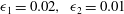

A transcritical case (
 $\mathit{Fr}=1$
) when the first obstacle is larger is shown in figure 15 for quite small amplitudes. At the first stage (
$\mathit{Fr}=1$
) when the first obstacle is larger is shown in figure 15 for quite small amplitudes. At the first stage (
 $t=150$
), each obstacle generates elevation and depression shocks that can be described by the single-obstacle theory. As time increases (
$t=150$
), each obstacle generates elevation and depression shocks that can be described by the single-obstacle theory. As time increases (
 $t=460$
), the downstream depression shock from the first obstacle interacts with the upstream elevation shock generated by the second obstacle, and an intermediate shock is formed. Because the first obstacle is larger, it now controls criticality. The intermediate shock travels downstream and passes over the second obstacle, leaving a locally steady elevation wave (
$t=460$
), the downstream depression shock from the first obstacle interacts with the upstream elevation shock generated by the second obstacle, and an intermediate shock is formed. Because the first obstacle is larger, it now controls criticality. The intermediate shock travels downstream and passes over the second obstacle, leaving a locally steady elevation wave (
 $t=1400$
) in a locally supercritical flow. The speed of the intermediate shock is greater than the speed of the downstream-travelling depression shock from the second obstacle. These two shocks merge and form a new shock moving further downstream (
$t=1400$
) in a locally supercritical flow. The speed of the intermediate shock is greater than the speed of the downstream-travelling depression shock from the second obstacle. These two shocks merge and form a new shock moving further downstream (
 $t=1800$
).
$t=1800$
).

Figure 15. Simulations for
 $\mathit{Fr}=1.0,~{\it\epsilon}_{1}=0.02,~{\it\epsilon}_{2}=0.01$
: (a)
$\mathit{Fr}=1.0,~{\it\epsilon}_{1}=0.02,~{\it\epsilon}_{2}=0.01$
: (a)
 $t=150$
; (b)
$t=150$
; (b)
 $t=460$
; (c)
$t=460$
; (c)
 $t=1400$
; and (d)
$t=1400$
; and (d)
 $t=1800$
.
$t=1800$
.
Next, we compare these nonlinear simulations quantitatively with the theoretical results. For
 ${\it\epsilon}_{1}=0.02$
, we find from the nonlinear simulations that the upstream shock magnitude and speed are
${\it\epsilon}_{1}=0.02$
, we find from the nonlinear simulations that the upstream shock magnitude and speed are
 ${\it\zeta}_{-}=0.1170$
and
${\it\zeta}_{-}=0.1170$
and
 $S_{-}=-0.0880$
, while the reduced model predicts that
$S_{-}=-0.0880$
, while the reduced model predicts that
 ${\it\zeta}_{-}=0.1155$
and
${\it\zeta}_{-}=0.1155$
and
 $S_{-}=-0.0866$
, and using the more exact formulae (2.16) and (2.17) leads to
$S_{-}=-0.0866$
, and using the more exact formulae (2.16) and (2.17) leads to
 ${\it\zeta}_{-}=0.1165$
and
${\it\zeta}_{-}=0.1165$
and
 $S_{-}=-0.0870$
. Similarly, for the second obstacle with
$S_{-}=-0.0870$
. Similarly, for the second obstacle with
 ${\it\epsilon}_{2}=0.01$
, the downstream shock magnitude and speed from the simulations are
${\it\epsilon}_{2}=0.01$
, the downstream shock magnitude and speed from the simulations are
 ${\it\zeta}_{+}=-0.0811$
and
${\it\zeta}_{+}=-0.0811$
and
 $S_{+}=0.0607$
, while the reduced model predicts that
$S_{+}=0.0607$
, while the reduced model predicts that
 ${\it\zeta}_{+}=-0.0816$
and
${\it\zeta}_{+}=-0.0816$
and
 $S_{+}=0.0612$
, and using the more exact formulae (2.16) and (2.17) leads to
$S_{+}=0.0612$
, and using the more exact formulae (2.16) and (2.17) leads to
 ${\it\zeta}_{-}=0.0802$
and
${\it\zeta}_{-}=0.0802$
and
 $S_{-}=-0.0604$
. These comparisons show very good agreement for small-amplitude obstacles. Further, the intermediate shock speed from the simulation is
$S_{-}=-0.0604$
. These comparisons show very good agreement for small-amplitude obstacles. Further, the intermediate shock speed from the simulation is
 $S_{int}=0.0260$
, while the theoretical expression (2.30) yields
$S_{int}=0.0260$
, while the theoretical expression (2.30) yields
 $S_{int}=0.0254$
. Also, note that for the nonlinear simulations when
$S_{int}=0.0254$
. Also, note that for the nonlinear simulations when
 $t=1400{-}1800$
, the two downstream depression shocks merge to form a new shock with the new speed
$t=1400{-}1800$
, the two downstream depression shocks merge to form a new shock with the new speed
 $S_{+}=0.0812$
, which is nearly the addition of
$S_{+}=0.0812$
, which is nearly the addition of
 $S_{int}$
and
$S_{int}$
and
 $S_{+}$
(for
$S_{+}$
(for
 ${\it\epsilon}=0.01$
).
${\it\epsilon}=0.01$
).
A case with higher obstacle amplitudes,
 ${\it\epsilon}=0.2,~{\it\epsilon}_{2}=0.1$
, is shown in figure 16. The flow behaviour is similar to the smaller-amplitude case. Here the intermediate shock speed from the simulation is
${\it\epsilon}=0.2,~{\it\epsilon}_{2}=0.1$
, is shown in figure 16. The flow behaviour is similar to the smaller-amplitude case. Here the intermediate shock speed from the simulation is
 $S_{int}=0.0281$
, but from (2.30),
$S_{int}=0.0281$
, but from (2.30),
 $S_{int}=0.0802$
. Again, the quite large difference is due to higher-order nonlinear effects.
$S_{int}=0.0802$
. Again, the quite large difference is due to higher-order nonlinear effects.

Figure 16. Simulations for
 $\mathit{Fr}=1.0,~{\it\epsilon}_{1}=0.2,~{\it\epsilon}_{2}=0.1$
: (a)
$\mathit{Fr}=1.0,~{\it\epsilon}_{1}=0.2,~{\it\epsilon}_{2}=0.1$
: (a)
 $t=50$
; (b)
$t=50$
; (b)
 $t=80$
; (c)
$t=80$
; (c)
 $t=400$
; and (d)
$t=400$
; and (d)
 $t=650$
.
$t=650$
.
4. Summary
Transcritical shallow-water flow over two localised and widely spaced obstacles has been examined using the fully nonlinear shallow-water equations (1.1) and (1.2) and with a combination of numerical simulations and theoretical analysis based on hydraulic flow concepts. For a single obstacle, the solution is typically a locally steady hydraulic flow over the obstacle contained between an upstream elevation shock and a downstream depression shock. For the case of two obstacles, there are two stages. At the first stage, each obstacle generates an upstream-propagating elevation shock and a downstream-propagating depression shock, each well described by the single-obstacle theory. Then, in the second stage, the downstream-propagating depression shock from the first obstacle interacts with the upstream-propagating elevation shock from the second obstacle to produce an intermediate shock, which propagates towards the larger obstacle, or, if the obstacles have equal heights, towards the second obstacle. There is an adjustment to a locally steady flow over both obstacles, where the higher obstacle controls criticality, or if the obstacles have equal heights, the second obstacle controls criticality. This outcome agrees with the analytical theory based on hydraulic flow concepts extended here from a single obstacle to two obstacles.
As is known, the case of flow over a single negative obstacle, or hole, is more complicated, as the shock waves are generated at the obstacle location; see Grimshaw & Smyth (Reference Grimshaw and Smyth1986) and Grimshaw et al. (Reference Grimshaw, Zhang and Chow2007, Reference Grimshaw, Zhang and Chow2009). Hence we expect that the case when either or both of the obstacles are holes could lead to different and more complicated scenarios, which will be the subject of a future study. Further, the present study is restricted to non-dispersive waves. Extensions to include even just weak dispersion using the forced KdV equation, or the fully nonlinear Su–Gardner equations, as done by El et al. (Reference El, Grimshaw and Smyth2009) for a single obstacle, will certainly lead to rather different behaviour. In that case, the shocks are replaced by undular bores and the shock interactions described here are replaced by the interactions of these nonlinear wave trains. For instance, some of the numerical simulations reported by Grimshaw et al. (Reference Grimshaw, Zhang and Chow2009) using just the forced KdV equation indicate that the interaction of these nonlinear wave trains can produce very complicated behaviour. This is also a topic needing much further study.
Acknowledgements
This work was supported by the Thailand Research Fund (TRF) and the Kasetsart University Research and Development Institute (KURDI) under grant no. RSA5680038 to the second author.
Appendix A
The weakly nonlinear model (1.5) for small-amplitude topographic forcing in the transcritical regime can be derived as follows. First, we introduce the Riemann variables
 $$\begin{eqnarray}R=U+2C,\quad L=U-2C,\quad C=\sqrt{H},\end{eqnarray}$$
so that (1.1) and (1.2) become
 $$\begin{eqnarray}R_{t}+(U+C)R_{x}+f_{x}=0,\quad L_{t}+(U-C)L_{x}+f_{x}=0.\end{eqnarray}$$
Then we assume that
 $f\sim {\it\alpha}^{2}$
where
$f\sim {\it\alpha}^{2}$
where
 ${\it\alpha}\ll 1$
, and that
${\it\alpha}\ll 1$
, and that
 ${\it\zeta}\sim {\it\alpha}$
,
${\it\zeta}\sim {\it\alpha}$
,
 ${\it\zeta}_{t}\sim {\it\alpha}^{2}$
,
${\it\zeta}_{t}\sim {\it\alpha}^{2}$
,
 $u=U-\mathit{Fr}\sim {\it\alpha}$
and
$u=U-\mathit{Fr}\sim {\it\alpha}$
and
 ${\it\Delta}=\mathit{Fr}-1\sim {\it\alpha}$
. Next, noting that
${\it\Delta}=\mathit{Fr}-1\sim {\it\alpha}$
. Next, noting that
 $U+C=\mathit{Fr}+1+O({\it\alpha})$
, we can find an approximation to the right-going Riemann invariant in the vicinity of the topography,
$U+C=\mathit{Fr}+1+O({\it\alpha})$
, we can find an approximation to the right-going Riemann invariant in the vicinity of the topography,
 $$\begin{eqnarray}R=\mathit{Fr}+2-\frac{f}{2}+O({\it\alpha}^{3})\quad \text{so that}\quad u+{\it\zeta}=\frac{{\it\zeta}^{2}}{4}+\frac{f}{2}+O({\it\alpha}^{3}).\end{eqnarray}$$
Here a transient propagating rapidly with a speed
 $\mathit{Fr}+1+O({\it\alpha})$
to the right is ignored. Then we find that, for the left-going Riemann invariant,
$\mathit{Fr}+1+O({\it\alpha})$
to the right is ignored. Then we find that, for the left-going Riemann invariant,
 $$\begin{eqnarray}\displaystyle & \displaystyle L=2U-(\mathit{Fr}+2)+\frac{f}{2}+O({\it\alpha}^{3})=\mathit{Fr}-2-2{\it\zeta}+\frac{{\it\zeta}^{2}}{2}+\frac{3f}{2}+O({\it\alpha}^{3}), & \displaystyle\end{eqnarray}$$
 $$\begin{eqnarray}\displaystyle & \displaystyle U-C=\frac{3U}{2}-\frac{\mathit{Fr}+2}{2}+\frac{f}{4}+O({\it\alpha}^{3})={\it\Delta}-\frac{3{\it\zeta}}{2}+O({\it\alpha}^{2}). & \displaystyle\end{eqnarray}$$
 $L$
in (A 2) reduces to (1.5), with an error of
$L$
in (A 2) reduces to (1.5), with an error of
 $O({\it\alpha}^{3})$
. Similarly, the mass shock condition in (1.4) reduces to (1.7) with an error of
$O({\it\alpha}^{3})$
. Similarly, the mass shock condition in (1.4) reduces to (1.7) with an error of
 $O({\it\alpha}^{3})$
, while the momentum shock condition has all terms of
$O({\it\alpha}^{3})$
, while the momentum shock condition has all terms of
 $O({\it\alpha}^{3})$
.
$O({\it\alpha}^{3})$
.


