


Introduction
The impedance properties of a wire grid with different background media have been of an interest to scientific community because of their important technical applications [Reference Larsen1–Reference Awan21]. They have applications in impedance matching, filters, artificial dielectrics or lens, electromagnetic shields, screens, antenna reflectors, and epsilon negative metamaterials. The electromagnetic properties of a parallel wire grid composed of infinite length conducting wires have been studied by Larsen [Reference Larsen1]. According to Larsen, impedance properties of a wire grid can be used for impedance matching, filters, and artificial dielectrics. The reflection and transmission properties of a parallel wire grid composed of conducting or perfectly electric conducting wires have been investigated by some authors [Reference Lewis and Casey2–Reference Manabe and Murk5]. Lewis and Casey [Reference Lewis and Casey2] have investigated the reflection and transmission properties of a resistive wire grid. They argued that the amplitude of reflection coefficient decreases with the increase of resistivity of wires. Wait [Reference Wait3] has studied the reflection properties of a planar wire grid under arbitrary incidence having arbitrary polarization. He has derived a general reflection coefficient without placing any restrictions upon incidence angle, polarization, and conductivity of wires. The transmission properties of a wire grid using parabolic equation method have been analyzed by Mias and Constantinou [Reference Mias and Constantinou4]. They also studied a wire grid as an electromagnetic screen. Manabe and Murk [Reference Manabe and Murk5] have investigated the reflection and transmission characteristics of a wire grid with slight irregularity in grid position and grid rotation. They have used the T-matrix approach for their proposed solution and also incorporated mutual coupling effects. Recently, Awan [Reference Awan6] has studied the reflection and transmission properties of a wire grid composed of lossy and lossless wires embedded in single negative or single zero metamaterial media. He concluded that a lossy wire grid becomes transparent to the incoming normal incident wave provided that if the background medium is Mu zero medium.
The scattering properties of a parallel wire grid has been studied analytically by Richmond [Reference Richmond7] and experimentally by Lewis and et al. [Reference Lewis, Fortuny-Guasch and Sieber8]. A wire grid as an electromagnetic shield has been investigated by authors [Reference Young and Wait9–Reference Lovat12]. Young and wait [Reference Young and Wait9,Reference Young and Wait10] have shown that an ensemble of infinitely long thin parallel wires can be taken as an electromagnetic shield. These shielding properties have been further explored in [Reference Celozzi, Araneo and Lovat11,Reference Lovat12]. Samii and Lee [Reference Samii and Lee13] have studied a wire grid as an antenna reflector which is composed of thin wires. Such type of antenna reflectors are light weight and have reduced wind effects. A two-dimensional extension of a wire grid can be taken as a wire medium or epsilon-negative metamaterial and have been studied by Belove et al. [Reference Belov, Tretyakov and Viitanen14] and by Awan [Reference Awan15]. The impedance characteristics of a parallel wire grid with the free space background have been studied by many authors [Reference Macfarlane16–Reference Awan21]. A study of impedance properties of a parallel wire grid under oblique angles of incidence has been carried out by Macfarlane [Reference Macfarlane16] and Marcuvitz [Reference Marcuvitz17]. An effective or surface impedance of a wire grid with the free space background and placed parallel to earth's surface has been discussed by Wait [Reference Wait18]. He has shown that this surface impedance decreases in value by raising the grid above the ground. The impedance boundary conditions for a sparse parallel wire grid with the free space background have been investigated in [Reference Tretyakov19,Reference Yatsenko, Tretyakov, Maslovski and Sochava20]. Yatsenko et al. [Reference Yatsenko, Tretyakov, Maslovski and Sochava20] concluded that if the spacing among wires is equal to the free space wavelength then the wire grid becomes transparent to the incoming wave. The effects of positioning errors upon the impedance, reflection, and transmission properties of a parallel wire grid with the free space background have been investigated by Awan [Reference Awan21]. He found that by increasing the positioning errors in the wires of the grid increases the magnitude of surface impedance. In all the papers cited above, a wire grid is assumed to place either in free space background or metamaterial background media. According to the author, surface impedance properties of a copper wire grid with lossless chiral or frequency-dispersive lossy chiral [Reference Lindell, Sihvola, Tretyakov and Viitanen22] background media have not been explored previously and is a topic of present study. The impedance properties of a wire grid with free space or dielectric background find potential applications in the designing of microwave lenses, various forms of shielding, antenna reflectors, impedance transformer networks used in the microwave engineering, and recently in the designing of metasurface, see for example [Reference Tretyakov23]. When such type of wire grid is placed in the chiral background then we have a greater control over the impedance characteristics of this wire grid due to an additional parameter of chirality. By varying the chirality parameter of the background medium, the impedance magnitude can be enhanced or diminished as compared to the free space or dielectric background. Thus, this type of control over the impedance properties due to an additional chirality signify the novelty of the proposed work and have not been studied previously.
In this paper, the effects of several background chiral media upon the surface impedance of a wire grid have been investigated. Using wavefield decomposition approach and with the application of impedance boundary conditions for a wire grid, the surface impedance of a wire grid embedded in a chiral background has been derived. It is found that surface impedance of a wire grid with the chiral background is frequency as well as spatially dispersive. The word spatial dispersion is used because its surface impedance is a function of incident wave vector components. Firstly, the effects of lossless chiral background media including strong chiral and chiral nihility background media upon the surface impedance of a copper wire grid have been investigated. It is found that for a chiral nihility background, the surface impedance magnitude is almost zero and is nearly independent of incident polar angle. From here it can be concluded that the surface impedance of a copper wire grid with chiral nihility background has very weak spatial dispersion effects. Secondly, the effects of lossy frequency-dispersive chiral background media upon the surface impedance of a copper wire grid have been studied. Finally, the effects of the realistic chiral background medium upon the surface impedance magnitude have been investigated. It is found that the magnitudes of surface impedances of copper wire grid embedded in realistic chiral and free space background media are nearly same for smaller values of polar angles. For polar angle closer to the right angle, the impedance magnitude of a wire grid embedded in the realistic chiral background is smaller than if the same wire grid is placed in the free space.
Surface impedance of a wire grid with chiral background
It is assumed that a wire grid consists of parallel cylindrical wires which are aligned along z-axis. The length of each wire is taken to be infinite and these wires are placed periodically along y-axis. The consecutive spacing among wires along y-direction is d y. The radius of each wire is taken to be a. The axial impedance per unit length of each wire is assumed to be Z w and given by [Reference Mias and Constantinou4,Reference Awan6],
 $$ Z_{w} = {\eta_{w} \over 2\pi a}{I_{0}(\gamma_{w}a) \over I_{1}(\gamma_{w}a)} $$
 $$ \eta_{w} = \sqrt{\,j\omega\mu_{w}/(\sigma_{w}+j\omega\epsilon_{w})} \qquad \gamma_{w} = \sqrt{\,j\omega\mu_{w}(\sigma_{w}+j\omega\epsilon_{w})} $$
where εw, μw, and σw are permittivity, permeability, and conductivity of wire material, respectively. The factors I 0( · ) and I 1( · ) represent the modified Bessel functions of order zero and one, respectively. It is important to note that for perfectly conducting wires, we have Z w = 0. The geometry of the wire grid is shown in Fig. 1.

Fig. 1. A wire grid composed of periodic arrangements of cylindrical wires and placed in a chiral background. Each wire is characterized by an axial impedance of Z w.
It is assumed that this wire grid is placed in the chiral background which is characterized by the relative permittivity εr, relative permeability μr, and relative chirality parameter of κr. It is known that the chiral medium is bi-refringent and allows two types of waves to exist in it. One of the waves is called right circularly polarized (RCP) wave and the other is known as a left circularly polarized (LCP) wave. The equivalent bulk wave numbers associated with RCP and LCP waves are k + and k −, respectively. They are expressed in mathematical forms as below [Reference Lindell, Sihvola, Tretyakov and Viitanen22],
 $$ k_{+} = k_{o}n_{+} \quad {\rm and} \quad k_{-} = k_{o}n_{-} $$
 $$ n_{+} = \sqrt{\epsilon_{r}\mu_{r}}(1+\kappa_{r}) \quad {\rm and} \quad n_{-} = \sqrt{\epsilon_{r}\mu_{r}}(1-\kappa_{r}) $$
where k o is free space wave number. The wave impedance of a chiral background is taken to be η = ηo(μr/εr)1/2 where ηo is intrinsic impedance of the free space. It is clear fromequations (3)–(4) that both wave numbers are positive provided that  $\kappa ^{2}_{r} \lt $ 1 [Reference Lindell, Sihvola, Tretyakov and Viitanen22]. In this case, both refractive indices n +, n − are positive. In case if
  $\kappa ^{2}_{r} \gt $ 1 then one of the refractive index, i.e. n − become negative whereas the refractive index n + remains positive. This gives rise to interesting phenomena that conventional negative index metamaterial does not exhibit, such as negative reflection for electromagnetic waves incident onto a mirror embedded in such a medium. This type of chiral medium is known as a strong chiral medium in the literature [Reference Zhang and Cui24]. On the other hand, for a chiral nihility medium, we have εr ≈ 0, μr ≈ 0, and κr ≠ 0 [Reference Qiu, Burokur, Zouhdi and Li25].
It is known that right-handed and left-handed fields in a chiral background medium are independent and do not couple [Reference Lindell, Sihvola, Tretyakov and Viitanen22]. Therefore, we can write these field components of an incident plane wave as two independent plane waves. These incident plane waves can be written as,
 $$ {\bf E}_{\pm}({\bf r}) = {\bf E}_{\pm}e^{-j{\bf k}_{\pm}\cdot {\bf r}} $$
with
 $$ {\bf k}_{\pm} = \hat{{\bf k}}k_{\pm} = \hat{{\bf x}}k^{\pm}_{x} + \hat{{\bf y}}k^{\pm}_{y} + \hat{{\bf z}}k^{\pm}_{z} $$
where k+ · E+ = 0 and k− · E− = 0. It should be noted that positive sign (+) subscript or superscript has been used for quantities related to right handed fields. On the other hand, negative sign (−) subscript or superscript represent quantities related to left-handed fields. These notations have been used throughout the study. These incident waves induce currents inside the wires of the grid. It is assumed that wires are taken to be infinitesimally thin, i.e. |k ±|a ≪ 1 therefore no circumferential currents induce inside the wires of a grid. Only axial currents are induced in the wires. Using theory outlined in [Reference Awan6,Reference Tretyakov19–Reference Awan21], the cell averaged induced current densities are defined as J + = I +/d y and J − = I −/d y. In this case, J +, J − are induced current densities due to incident RCP and LCP waves, respectively. They are found by applying the boundary conditions at the surface of reference wire which is located at y = 0 and given below,
 $$ E^{loc}_{\pm,z} + E^{0}_{\pm,z}= Z_{w}I_{\pm} $$
 $$ E^{0}_{\pm,z}= -{\eta \over 4}I_{\pm}e^{-jk_{z}^{\pm}z} {(k^{\pm}_{\rho})^{2} \over k_{\pm}}\left[1-j {2 \over \pi} (\ln(k^{\pm}_{\rho}a/2)+C)\right] $$
 $$ E^{loc}_{\pm,z}= E^{z}_{\pm}e^{-jk_{z}^{\pm}z}+ {E^{sc}_{\pm,z}} $$
 $$ E^{sc}_{\pm,z} = - {\eta \over 4}I_{\pm}e^{-jk_{z}^{\pm}z} {(k^{\pm}_{\rho})^{2} \over k_{\pm}}\sum_{i=-\infty, i\neq 0}^{i=+\infty}e^{-jk_{y}^{\pm}y_{i}}H^{(2)}_{0}(k^{\pm}_{\rho}\vert y_{i}\vert ) $$
with  $E^{z}_{\pm } = \hat { {\bf z}}\cdot {\bf E}_{\pm }$ and C=0.5772 is an Euler's constant. Here
  $k^{\pm }_{\rho } = (k^{2}_{\pm } - (k^{\pm }_{z})^{2})^{1/2}$ and the factor
  $H^{(2)}_{0}(\cdot )$ represents the Hankel function of second kind with order zero. Also y i = id y which represents the location of an ith wire in the grid with i=0, ±1, ±2,.........., ± ∞. Using this notation, it is argued that the reference wire is located at i = 0. The z-component of the total scattered electric field
  $E^{sc}_{+,z}$ appearing in equation (10) represents the contributions of the z-components of the scattered electric fields from the rest of the wires in the grid at reference wire due to an RCP incident wave. Similar definition exists for the z-component of the total scattered electric field
  $E^{sc}_{-,z}$ due to an LCP incident wave. After some manipulations and using the theory outlined in [Reference Awan21] these induced current densities J ± can be written as,
 $$ J_{\pm} = {(2/\eta)(\vert k^{\pm}_{x}\vert /k_{\pm}) \over (2/\eta)(\vert k^{\pm}_{x}\vert /k_{\pm})Z_{w}d_{y}+(k^{\pm\,2}_{\rho}/k^{2}_{\pm})(1 + jg^{\pm}_{\,p}(\vert k^{\pm}_{x}\vert /k_{\pm}))}E^{\pm}_{z} $$
 $$ g^{\pm}_{\,p} = {k_{\pm}d_{y} \over 2}\left\{\ln\left({d_{y} \over 2\pi a}\right) + (1/2)S^{\pm} \right\} $$
 $$ S^{\pm} = \sum_{m = -\infty,\,m \neq 0}^{m = +\infty}\left[{2\pi \over \sqrt{(k^{\pm}_{y}d_{y} + 2\pi m)^{2}-(k^{\pm}_{\rho}d_{y})^{2}}}- {1 \over \vert m\vert }\right] $$
For surface impedance of a wire grid, it is required that |k ±|d y < π. This ensures that there exists no grating lobes and is an essential condition for the homogenized description of a wire grid. In this case, the whole wire grid can be replaced by average current sheets carrying electric surface currents  $J^{s}_{\pm }$. The characteristics of such a grid can be described in terms of the grid impedances Z ±, which connects the averaged electric field magnitudes in the grid plane to the averaged current density magnitudes J ±. In this case,
  $E^{T+}_{z}$ is the z–component of total cell averaged electric field in the grid plane. This total field is the sum of the z-component of incident electric field and the z-component of the scattered plane wave field created by an equivalent current sheet
  $J^{s}_{+} = J_{+}e^{-jk^{+}_{y}y-jk^{+}_{z}z}$. Similar definition exists for the cell averaged electric field
  $E^{T-}_{z}$. These total fields can be written as,
 $$ \eqalign{ E^{T\pm}_{z} =& \left({E^{\pm}_{z} \over J_{\pm}}-{\eta \over 2}(k^{\pm\,2}_{\rho}/k^{2}_{\pm}){k_{\pm} \over \vert k^{\pm}_{x}\vert }\right)J_{\pm}e^{-jk^{\pm}_{y}y-jk^{\pm}_{z}z} \cr &= Z^{\pm}J_{\pm}e^{-jk^{\pm}_{y}y-jk^{\pm}_{z}z} } $$
It is known from [Reference Lindell, Sihvola, Tretyakov and Viitanen22] that J ± = J/2 with J = J + + J −. Therefore, the surface impedance of a wire grid embedded in the chiral background can be written as,
 $$ Z_{s} = {1 \over 2}(Z^{+} + Z^{-}) = Z_{w}d_{y} + {\,j\eta \over 4}\left\{g^{+}_{\,p}{k_{\rho}^{+\,2} \over k_{+}^2} +g^{-}_{\,p} {k_{\rho}^{-\,2} \over k_{-}^2}\right\} $$
It is clear from equation (15) that the surface impedance Z s of a wire grid embedded in the chiral background shows frequency as well as spatial dispersion. This surface impedance is also dependent upon the chirality of the background medium. It can be seen from equations (12), (13), and (15) that if the background medium is the free space then we have  $k_{z}^{+} = k_{z}^{-} = k_{z}$, k + = k − = k o, η = ηo, and
  $g^{+}_{p} = g^{-}_{p} = g_{p}$. Using this information in equation (15), it is found that the surface impedance of a wire grid Z s becomes same as given in [Reference Awan6,Reference Tretyakov19–Reference Awan21] for the free space background. In usual spherical coordinate system, the components of wave vector are defined as
  $k^{\pm }_{x} = -k_{\pm }\sin \theta \cos \phi $,
  $k^{\pm }_{y} = k_{\pm }\sin \theta \sin \phi $, and
  $k^{\pm }_{z} = -k_{\pm }\cos \theta $. It is important to note that for the normal incidence, we have θ = π/2 and ϕ = 0.
The electromagnetic parameters of chiral medium given by equations (3)–(4) are based upon Kong constitutive relationships and are often used when one is not interested in frequency dispersion. In this case, parameters of the medium are taken to be constant. On the other hand, if someone is interested in the frequency-dispersive nature of the chiral medium which takes into account appropriate losses, it is desired to use frequency-dispersive models for εr(ω), μr(ω), and κr(ω). It is known from [Reference Lindell, Sihvola, Tretyakov and Viitanen22,Reference Grande, Barba, Cabeceira, Represa, Karkkainen and Sihvola26,Reference Huang, Li and Lin27] that the permittivity and permeability of artificial chiral medium follow a second-order Lorentz model. Likewise, the frequency dependence of chirality parameter is based upon the Condon model [Reference Lindell, Sihvola, Tretyakov and Viitanen22]. Using this information, the mathematical expressions for εr(ω), μr(ω), and κr(ω) for frequency-dispersive chiral medium can be written as,
 $$ \epsilon_{r}(\omega) = \epsilon_{\infty} + {(\epsilon-\epsilon_{\infty})\omega_{0e}^{2} \over \omega_{0e}^{2} - \omega^{2} +j2\Gamma_{e}\omega_{0e}\omega} $$
 $$ \mu_{r}(\omega) = \mu_{\infty} + {(\mu-\mu_{\infty})\omega_{0m}^{2} \over \omega_{0m}^{2} - \omega^{2} +j2\Gamma_{m}\omega_{0m}\omega} $$
 $$ \kappa_{r}(\omega) = {\kappa(\omega) \over \sqrt{\mu_{r}(\omega)\epsilon_{r}(\omega)}} $$
 $$ \kappa(\omega) = {\tau\omega^{2}\omega \over \omega_{0}^{2} - \omega^{2} + j2\Gamma\omega_{0}\omega} $$
where ε and μ are low-frequency values of permittivity and permeability while ε∞ and μ∞ represent high-frequency values of permittivity and permeability, respectively. The factor ω0e represents characteristic resonant frequency and Γe shows the associated damping factor for the permittivity. Likewise, the factors ω0m and Γm represent characteristic resonant frequency and associated damping factor for the permeability, respectively. Here τ is a time constant, ω0 is a characteristic resonant frequency whereas Γ is a damping factor for the chirality parameter. It is known from [Reference Grande, Barba, Cabeceira, Represa, Karkkainen and Sihvola26,Reference Huang, Li and Lin27] that the resonance frequencies of εr(ω), μr(ω), and κr(ω) are found to be very close in experiments, therefore, it can be argued that ω0e = ω0m = ω0.
An artificial chiral medium whose electromagnetic parameters, i.e. εr(ω), μr(ω), and κr(ω) are governed by the equations (16)–(19) can be realized by four-folded rotated metallic Ω- resonators [Reference Zhao, v and Soukoulis28]. It is seen from [Reference Zhao, v and Soukoulis28] that the chirality parameter κ(ω) given inequation (19) is dependent upon the volume of the unit cell, cross-sectional area of loop, number of Ω- resonators in one unit cell, and length of short wires comprising the resonator. Likewise, κ(ω) is also dependent upon the resistance, inductance, and capacitance of equivalent RLC circuit model of the Ω- resonator. By proper selection of these parameters, one can control the chirality parameter of an artificial chiral medium.
Numerical results
For numerical results, it is assumed that wires of the grid are made of a copper material. The electromagnetic parameters of copper wires for equations (1)–(2) are taken to be εw = εo, μw = μo, and σw = 5.8 × 10⁷ S/m and has been taken from Young and Wait [Reference Young and Wait29]. Here εo, μo are permittivity and permeability of the free space, respectively. The spacing among wires are taken to be d y = 10.2 mm at an operating free space wavelength λo of 50 mm for Figs 3–7 and Figs 9–10. In order to ensure that the wires of the grid are thin, the radius of each wire is taken to be a = d y/50. It is important to note that the proposed formulation can also be applied to higher frequencies, e.g. THz frequencies. For this one needs to use the Drude-like frequency response of metals at these frequencies. In order to highlight the influences of background chirality upon the surface impedance of a wire grid, the relative permittivity and the relative permeability have been assumed to be fixed, i.e. εr = 1.23 and μr = 1 for chiral and strong chiral background media for Figs 3–8 except for chiral nihility background where εr = 0.001 and μr = 0.001.
It is already mentioned in section “Surface impedance of a wire grid with chiral background” that if we take κr = 0, εr = 1, and μr = 1 for the background medium then the mathematical expression of surface impedance Z s given by equation (15) becomes same as that given in [Reference Awan6,Reference Tretyakov19–Reference Awan21] for the free space background. Likewise, if we assume that wires of the grid are made of perfectly electric conducting martial, i.e. Z w = 0 and placed in the free space background then we can find the reflection coefficient based upon this surface impedance Z s. For the normal incidence, the reflection coefficient R and transmission coefficient T can be computed as, R = −1/(1 + (2/ηo)Z s) and T=1+R [Reference Awan6,Reference Tretyakov19,Reference Yatsenko, Tretyakov, Maslovski and Sochava20]. Using this information, the surface impedance magnitude and their corresponding reflection and transmission coefficients have been shown in Fig. 2. It is found that the reflection and transmission coefficients based upon this equivalent surface impedance Z s are in good agreement with the previous work [Reference Tretyakov19,Reference Yatsenko, Tretyakov, Maslovski and Sochava20]. This validates the accuracy of the proposed formulation.

Fig. 2. (a) The magnitude of surface impedance and (b) reflection and transmission coefficients of a wire grid composed of perfectly conducting wires with the free space background, i.e. κr = 0, εr = μr = 1 as a function of d y/λo.
The influences of incident angles upon the magnitude of surface impedance of a wire grid with various background media have been shown in Fig. 3–4. For Figs 3–4, one of the incidence azimuth angle is fixed, i.e. ϕ = π/4. In Fig. 3, the influences of various background chiral media upon the magnitude of surface impedance as a function of angle θ have been shown. It is seen that for κr = 0.1, 0.5, and 0.99, the magnitudes of surface impedances are nearly same for 0.001° ≤ θ ≤ 30° as that of magnitude of surface impedance with the free space background. Thus, it is concluded that if θ is small then the magnitude of impedance nearly seems to be independent of the background chirality. On the other hand, the magnitude of impedance increases with the increase of background chirality for 30° ≤ θ ≤ 90°. It is found that significant increase in the magnitude of surface impedance for chiral background having chirality parameter close to unity, i.e. κr = 0.99 is observed at θ = 90°. The effects of strong chiral and chiral nihility background media upon surface impedance magnitude have been given in Fig. 4. For strong chiral background, the chirality is assumed to be 1.2 and the electromagnetic parameters for chiral nihility background are taken to be εr = 0.001, μr = 0.001, and κr = 0.99. It is seen that strong chiral background significantly enhances the surface impedance magnitude of a grid for incident polar angles θ closer to 90° as compared to the free space background. An interesting result is found in case of a wire grid embedded in a chiral nihility background, it is seen that the magnitude of surface impedance is approximately close to zero and independent of the considered range of incident polar angle θ. Thus, it is concluded that impedance of wire grid with chiral nihility background is almost independent of spatial dispersion.
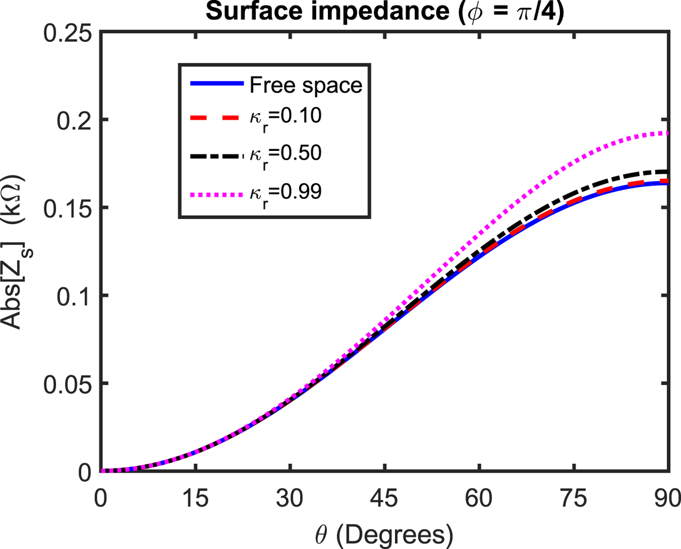
Fig. 3. Effects of various chiral background media upon the magnitude of surface impedance of a wire grid. In this case, ϕ = 45° whereas θ is variable.

Fig. 4. A comparative study of the surface impedance magnitude for strong chiral, chiral nihility, and free space background media. Here one of the incidence angle is fixed, i.e. ϕ = 45° and θ is variable.
Figures 5–6 deal with the effects of various chiral background media including strong chiral and chiral nihility upon impedance magnitude for incident wave-vectors k+, k− lie in the yz-plane which is a plane parallel to the plane of a wire grid. From Fig. 5, it is studied that the value of surface impedance magnitude increases with the increase of background chirality for polar angles θ closer to π/2. The significant enhancement in impedance magnitude is observed for θ = π/2 with chirality of background closer to unity, i.e. κr = 0.99. In Fig. 6, the effects of strong chiral and chiral nihility background upon the magnitude of surface impedance have been shown. It is observed that for polar angles lying in the range 0° ≤ θ ≤ 45°, the impedance magnitude of a grid with the free space background is almost same as that of the same grid embedded in the strong chiral background. For angles 45° ≤ θ ≤ 90°, the value of surface impedance with the strong chiral background increases significantly as compared to the free space background with the highest value of 0.75 kΩ for a polar angle of π/2. It is once again observed that for the chiral nihility background the surface impedance magnitude is very small and almost independent of the considered range of incident polar angles.

Fig. 5. Influences of several chiral background media upon the magnitude of surface impedance of a wire grid where ϕ = 90°. In this case, θ is variable.
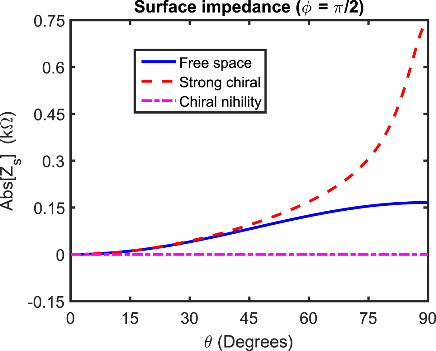
Fig. 6. Influences of strong chiral and chiral nihility background media upon the magnitude of surface impedance of a wire grid and their comparison with the free space background. Here we have ϕ = 90° and θ is variable.
The effects of chirality of background media upon the magnitude of surface impedance are given in Fig. 7. In this case, one of the angle is taken to be fixed, i.e. θ = π/2 whereas ϕ isa variable. In case of ϕ = 0 which corresponds to the normal incidence, the magnitude of impedance increases as the value of κr increases from 0.01 to 1.2. It is found that at κr = 1.2, the magnitude of impedance for ϕ = 0 becomes 0.1745 kΩ. The angles ϕ = π/4, π/2 corresponds to oblique incidence. For these angles, the magnitude of surface impedance increases as the value of κr increases. It is clear from Fig. 7 that for κr = 1.2, the magnitude of impedance becomes 0.2153 kΩ for ϕ = π/4. On the other hand, the magnitude of impedance for κr = 1.2 and ϕ = π/2 enhances significantly and becomes 0.742 kΩ. It is noticed that κr = 1.2 corresponds to the strong chiral background.

Fig. 7. Influences of various incident angles ϕ and chirality parameter upon the magnitude of surface impedance with θ = 90°.
The surface impedance magnitude as a function of d/λo for various values of background chirality κr are given in Fig. 8 under normal incidence. It is found that for the free space background medium if d/λo = 1 then the grid parameter g p as given byequation (12) becomes infinite and as a result no currents are induced in wires of a grid. Thus, a wire grid becomes transparent to the incoming wave with zero reflection. On the other hand, for a chiral background with the chirality κr of 0.25, this phenomenon of zero reflection occurs at relatively smaller value of d/λo as compared to the free space background, i.e. d/λo = 0.7215. Likewise, if the value of chiral background is taken to be very large and close to unity, i.e. κr = 0.99 then this phenomenon is observed at two specific values of d/λo, i.e. d/λo = 0.4530 and d/λo = 0.9060. Thus, it is concluded that with chiral background, zero reflection can be obtained at relatively smaller value of spacing among wires as compared to spacing among wires with the free space background.

Fig. 8. The magnitude of surface impedance as a function of d y/λo for various chirality parameters whereas the incident wave is assumed to be normal.
It is known that frequency-dispersive nature of the chiral medium is described by the one resonance Condon model [Reference Lindell, Sihvola, Tretyakov and Viitanen22]. This shows that the chiral medium has complex valued permittivity, permeability, and chirality at a given frequency of interest. Therefore, in order to study the frequency-dispersive nature of surface impedance of a wire grid embedded in the chiral background, it is desired to use frequency-dispersive electromagnetic parameters of the chiral background as given byequations (16)–(19). For Fig. 9, it is assumed that the direction of incident wave is fixed, i.e. θ = π/2 and ϕ = π/4. In this case, incident wave vectors k± lie in the xy-plane. It is observed that with the increase in frequency, the magnitude of surface impedance of a wire grid with the free space background increases. For a frequency-dispersive chiral background, the various parameters appearing in equations (16)–(19) are taken from [Reference Grande, Barba, Cabeceira, Represa, Karkkainen and Sihvola26,Reference Huang, Li and Lin27]. They are ε = 6, ε∞ = 4, μ = 1.5, μ∞ = 1, τ = 15 ps, ω0e = ω0m = ω0 = 6π GHz, and Γe = Γm = Γ = δ = 0.2. In this case, it is seen that for frequency f lying in the range 1 GHz ≤ f < 3.3363 GHz, the impedance magnitude is greater than the corresponding impedance magnitude of same wire grid placed in the free space background. For frequency lying in the range 3.3363 GHz < f ≤ 6 GHz, the impedance magnitude is smaller than the impedance magnitude of wire grid with the free space background. From this analysis, it is concluded that at some critical frequency f c, i.e. f c = 3.3363 GHz, the impedance magnitude of a wire grid embedded in a certain frequency-dispersive chiral background is equal to the impedance magnitude of the same wire grid when embedded in the free space background. For a frequency-dispersive chiral background having relatively larger damping factor of δ = 0.9, this critical frequency f c becomes 3.6435 GHz. This is clear from Fig. 9. The frequency dispersion characteristics of a wire grid with various chiral background media have been shown in Fig. 10 for incident angles θ = π/2 and ϕ = π/2. In this case, we have  $k^{\pm }_{x} = 0$,
  $k^{\pm }_{y} = k_{\pm }$, and
  $k^{\pm }_{z} = 0$. All the chiral background media considered for Fig. 9 have also been considered for Fig. 10. The comparative study of surface impedance magnitudes for frequency-dispersive chiral and free space background media as considered in Figs 9 and 10 ata frequency of 6 GHz are given in Table 1.

Fig. 9. The magnitude of surface impedance as a function of frequency for frequency-dispersive chiral background media and their comparisons with the magnitude of surface impedance of a wire grid with the free space background. In this case, ϕ = 45° and θ = 90°.

Fig. 10. The magnitude of surface impedance as a function of frequency for various lossy chiral background media. Here we have assumed ϕ = 90° and θ = 90°.
Table 1. Comparative study of surface impedance magnitudes for dispersive chiral and free space background media at an operating frequency of 6 GHz for case 1 where θ = π/2, ϕ = π/4 and case 2 where θ = π/2, ϕ = π/2.

In Fig. 11, a comparative study of the magnitude of surface impedance for free space and realistic chiral background media have been shown. For the realistic chiral background, the complex valued electromagnetic parameters have been adopted from [Reference Wang, Lau, Yung and Chen30] at an operating free space wavelength of 30.4 mm. They are taken to be εr = 3.514 − j 3.760, μr = 0.820 − j 0.359, and κr = 0.06568 − j 0.04589. For this case, the operating frequency is relatively high and in order to satisfy the requisite condition |k +|d y, |k −|d y < π for homogenization, the spacing among wires are assumed to be 6.5 mm. It is clear from Fig. 11 that for smaller values of θ, the magnitudes of surface impedances of wire grid embedded in realistic chiral and free space background media are nearly same. As the value of θ increases and approaches 90° where we have normal incidence, the magnitude of impedance of a wire grid embedded in the realistic chiral background is smaller than if the same wire grid is placed in the free space.
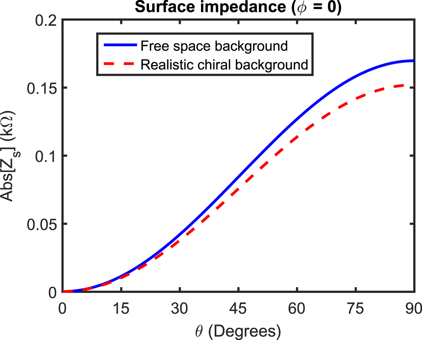
Fig. 11. A comparative study for the surface impedance magnitude of a wire grid embedded in the free space and the realistic chiral background.
Conclusions
The surface impedance properties of a parallel wire grid with several chiral background media including chiral nihility and strong chiral have been investigated. During the analysis, it is found that the surface impedance of a wire grid with the chiral background is frequency as well as spatially dispersive. The spatial dispersion nature of the surface impedance describes that it is dependent upon the incidence angles. The proposed theory is general and can be applied to any type of incident polarization, conductivity of wires, and chiral background. It is shown that a wire grid with chiral nihility background has nearly zero surface impedance magnitude and independent of incident polar angles. A strong chiral background significantly enhances the surface impedance magnitude of a wire grid at right incident polar angle as compared to the free space background. It is investigated that zero reflection condition for the chiral background medium can be obtained at relatively smaller value of spacing among wires as compared to the free space background. From the analysis, it is also found that at some critical frequency, the impedance magnitude of wire grid embedded in the frequency-dispersive chiral background is equal to the impedance magnitude of the same wire grid when embedded in the free space background. Thus, it is argued that an electromagnetic appearance of a wire grid with free space and specific frequency-dispersive chiral background is same at critical frequency which may find applications in electromagnetic illusions. The impedance magnitude of a wire grid embedded in the realistic chiral background is smaller as compared to impedance magnitude of the same wire grid when placed in the free space background for values of incident polar angles closer to right angle.
Author ORCIDs
Z. A. Awan, 0000-0002-5193-1046
 Zeeshan Akbar Awan received a Ph.D. degree in Electronics from the Quaidi-Azam University, Islamabad, Pakistan in 2013. He is presently an assistant professor at the same university. He has worked as a Post-Doctoral candidate within LEOST Laboratory of the COSYS department in IFSTTAR, Lille, France from January to July 2018. He has authored or co-authored more than 20 research articles. His research interests include metamaterials, metasurfaces and antenna theory.


