


Introduction
Pulse compression is a technique used in radar systems to increase both range resolution and signal-to-noise ratio (SNR) [Reference Skolnik1]. Furthermore, pulse compression waveforms are used in solid-state radar systems, which are typically peak power limited to low values, but can sustain very long pulse widths and generate average power values comparable with the tube systems with greater reliability [Reference David2]. Pulse compression waveforms are used in different radar systems such as airborne radar, surveillance radar, tracking radar, weather radar, synthetic aperture radar (SAR), and ground penetrating radar etc.
The basic principle of pulse compression is to transmit a long modulated pulse that has a high bandwidth, and then compress the target echo in the receiver using a filter matched with the transmitted pulse. By doing that, radar can utilize a long pulse to achieve large radiated energy and obtain the range resolution of a short pulse simultaneously [Reference Skolnik1]. Common forms of pulse compression signals are frequency modulated waveforms and phase coded (PC) waveforms, which have different responses in terms of Doppler tolerance, time-sidelobe level, and immunity against jamming.
Radars are vulnerable to different types of jammers that generate many deceptive false targets or mask the target echoes by increasing the noise level of the environment. Deceptive jammers transmit modified versions of the radar signal. Therefore, they benefit from the pulse compression gain of the radar-matched filter and they use jamming power efficiently. Whereas, noise jammers do not benefit from the pulse compression gain. Therefore, they need high-power transmission to be more effective [Reference Stimson, Griffiths, Baker and Adamy3].
On the basis of the discussion above, radar systems could be attacked by different jammers and it is so important to have radar signals that can mitigate jamming to discriminate true targets. In addition, peak sidelobes level (PSL) and Doppler tolerance of radar signals are critical properties in designing pulse compression radar. The optimum radar signal should have good Doppler tolerance to detect high-speed targets, and it should have low PSL to detect weak targets nearby the strong ones, and to mitigate jamming effect that tries to deceive the radar by creating side-lobes.
This paper reviews the commonly used radar signals, including frequency modulated waveforms and PC waveforms in the sections ‘Frequency Modulated Waveforms’, and PC Signals' respectively, where their main properties such as Doppler tolerance, time-sidelobe level, and immunity against jamming are presented. Finally, the practical guidance to select the best probe radar signal is given in the section ‘Conclusive Remarks’.
Frequency Modulated Waveforms
Frequency modulated waveforms are generated by modulating the frequency of the radar pulse. There are several types of frequency modulated waveforms such as linear frequency modulation (LFM) or chirp, nonlinear Frequency modulation (NLFM), and Costas coded signals etc.
LFM
LFM signal is commonly used in pulse compression radar for both surveillance and tracking radars due to its high Doppler tolerance. The complex envelope of LFM pulse is given by [Reference Curtis Schleher4]:
 $$x(t) = {\rm rect}(\displaystyle{t \over T})e^{\,j2\pi \mu t^2},\left \vert t \right \vert \lt \displaystyle{T \over 2},$$
where T is the chirp duration, B is the sweep bandwidth, and μ = ±B/T is the frequency modulation slope, which specifies the direction of the LFM sweep as up or down, corresponding to increasing and decreasing instantaneous frequency.
It is well known that the PSL of the compressed LFM pulse equals − 13.2 dB, which is relatively high. These time-sidelobes can shadow the weak return from small targets and go undetected in the presence of strong return of large targets. One solution to this problem is to use windowing functions. However, the range resolution is decreased and a SNR loss and peak gain loss occur as well [Reference Curtis Schleher4].
LFM waveform exhibits range-Doppler coupling property. Is that property good or bad? Argument for “good”: the target can still be detected up to Doppler shift equals to B/10 [Reference Skolnik1, Reference Richards5]. Argument for “bad”: if there is a Doppler mismatch, the measurement of range will be wrong!, and if the speed of the target is known then the true range can be obtained [Reference Richards5]. Furthermore, this property makes the chirp radar more vulnerable to different types of deceptive repeater jammers e.g. frequency-shifting jammer and interrupted sampling repeater jammer (ISRJ) [Reference Yong, Zhang and Yang6–Reference Baher Safa Hanbali and Kastantin10].
Frequency-shifting jammer instantly shifts the frequency of the radar signal to generate false targets that lead and lag behind the true target at the output of the radar detector. The jamming retransmission may take different modes such as single false target jamming, multiple-false targets jamming, and multiple-cover jamming [Reference Yong, Zhang and Yang6, Reference Baher Safa Hanbali and Kastantin10]. S.B.S. Hanbali et al. [Reference Baher Safa Hanbali and Kastantin11] address countering some types of frequency-shift jammers by using sweep bandwidth agility without degrading both the radar range resolution and the matched filter gain too much. By changing the sweep bandwidth, false targets appear in different range bins, but the true target remains in the same range bin, so it can be recognized easily. Recently, S.B.S. Hanbali et al. [Reference Baher Safa Hanbali and Kastantin12] propose a new anti-jamming technique to counter different types of frequency-shift jammers. The fractional Fourier transform (FrFT) is used to compress and separate the overlapping true target echo from jamming signals. However, the performance of FrFT is inferior to the matched filter by 3 dB.
ISRJ used one receive and transmit time-sharing antenna to sample and store segments of the radar signal and then it retransmits them toward the victim radar, so there is no need for high isolation of the two receive-transmit antennas used by frequency-shifting jammers. ISRJ generates many false targets at the output of the radar detector. These false targets consist of the main false target that always lags behind the true target by jammer's delay, and several other false targets that are located symmetrically around the main false target [Reference Wang, Liu, Zhang, Fu, Liu and Xie7]. Recently, a method is proposed to remove the ISRJ-based false targets by using short-time Fourier transform [Reference Gong, Wei and Li13], where it is found that the time-frequency characteristics of the ISRJ signal are discontinuous in the pulse duration, and a particular band-pass filter is generated to retain the true target signal and suppress the ISRJ signal. However, this method needs a high SNR to counter ISRJ because it is done before the pulse compression process. In addition, this is only applicable to counter ISRJ in the case of SAR [Reference Baher Safa Hanbali and Kastantin10].
The effective false targets of ISRJ lag behind the true target because of the jammer's delay; therefore they could be recognized by radar easily. In [Reference Li, Su, Gu, Ma and Chen8], Digital Radio Frequency Memory (DRFM) is applied to make the false targets lead the true one. However, in this case, the ISRJ can be countered by using the common electronic counter-countermeasures techniques that are used against DRFM e.g. orthogonal waveforms [Reference Baher Safa Hanbali and Kastantin10].
Under certain conditions, the ISRJ can cancel an ideal point target by superimposing on it a false target with the same amplitude and inverted phase [Reference Feng, Xu, Wang and Yang9]. S.B.S. Hanbali et al. [Reference Baher Safa Hanbali and Kastantin14] address countering active echo cancellation of self-protection ISRJ by introducing a linear phase shift of the transmitted LFM signal. By doing so, the true target and the jammer echo will be in phase. Consequently, the true target echo is augmented by jammer signal, converting the jamming signal from being destructive to being constructive.
SAR is used widely in both civil and military applications due to its great imaging ability over a long distance in all-weather conditions and throughout the daytime. Wideband LFM signals are widely used in SAR to achieve high-range resolution. In this case, the bandwidth of LFM signal is greater than the sampling rates of available analogue to digital converter (ADC) technology and therefore stretch processing (de-chirping) is employed [Reference O'Donnell15]. In [Reference Feng, TAO, YANG and LIU16], a jamming approach of applying ISRJ to de-chirping radar is presented. Recently, three-stage active cancellation method using frequency and delay time modulation to cancel out the target echo is developed to avoid detecting and observing the target of interest by the SAR [Reference Xu, Feng, Liu, Pan and Wang17]. Echo cancellation requires accurate amplitude match of cancellation signal and target echo at SAR receiver. Therefore, in the presence of amplitude mismatch, the target echo cannot be completely cancelled, thus, remains visible in the SAR image. To overcome that problem nonperiodic interrupted sampling modulation is used to produce a continuous jamming strip that covers the residual of the target in the SAR image [Reference Wu, Liu, Wang, Zhao and Xiao18].
NLFM
NLFM waveform has one advantage over LFM because it requires no weighting for time-sidelobe reduction. The FM modulation of the NLFM waveform is designed to provide the desired spectrum shape that yields the required PSL. This shaping is accomplished by increasing the rate of change of frequency modulation near the ends of the pulse and decreasing it near its center. Therefore, generating NLFM waveforms is more difficult than generating LFM waveforms. The frequency modulation function of NLFM waveform can be symmetrical or an asymmetrical e.g. as follows [Reference Skolnik1]:
 $$f\,(t) = B\left[ {\displaystyle{t \over T} + \sum\limits_{n = 1}^7 {k_n} {\rm sin}\displaystyle{{2\pi nt} \over T}} \right],$$
where T is the pulse duration, B is the sweep bandwidth, and the coefficients are [Reference Skolnik1]: k 1 = −0.1145, k 2 = 0.0396, k 3 = −0.0202, k 4 = 0.0118, k 5 = −0.0082, k 6 = 0.0055, k 7 = −0.0040.
Figure 1 shows the simulation results of PSL as a function of BT product when equation (2) is used. It is shown that higher BT product leads to lower PSL.

Fig. 1. The PSL of NLFM as a function of BT.
The primary disadvantage of the NLFM waveform is its Doppler sensitivity, the mainlobe of the compressed NLFM pulse is distorted and the time-sidelobes will be increased compared with those of the LFM. Therefore, NLFM can be used when the target speed is approximately known, and can be compensated in the matched filter [Reference Skolnik1].
Recently, jamming on NFLM radar has become an important topic in modern electronic warfare. An active cancelling system for three different NLFM signals is proposed in [Reference Yi, Wang and Huang19] to decrease radar detection.
Costas codes
Costas signal uses random frequency hopping to increase the bandwidth of the transmitting pulse and to avoid interception and jamming [Reference Jankiraman20]. The radar pulse is divided into N time slices each of duration t c. At any slice of these slices, only one frequency is transmitted, and each frequency is used only once. The complex envelope of Costas code is given by [Reference Touati, Tatkeu, Chonavel and Rivenq21]:
 $$ x(t)= \sum_{m=1}^{N-1}u_{m}(t-mt_{c}),$$
where:
 $$u_m(t) = {\rm rect}(\displaystyle{t \over {t_c}})e^{\,j2\pi f_mt},$$
and
 $${\rm rect}(\displaystyle{t \over {t_c}}) = \left\{ {\matrix{ {1,} \hfill & {0 \le t \le t_c} \hfill \cr {0,} \hfill & {{\rm elsewhere}.} \hfill \cr } } \right.$$
Hopping order strongly affects the ambiguity function of the signal. Therefore, Welch construction algorithm is usually used to find out the hopping order that makes the corresponding ambiguity function such as thumbtack [Reference Jankiraman20]. Consequently, Costas codes have very low Doppler tolerance, and they are unsuitable for detecting targets with high Doppler frequency. This problem can be overcome by using a bank of matched filters. Each filter is matched to a certain Doppler frequency, but this increases the complexity and cost of the radar's receiver.
All sidelobes, except for few around the origin, have an amplitude of 1/N [Reference Jankiraman20]. The improvement in delay-Doppler resolutions and ambiguity function sidelobes level needs an increase in the size of the code. A new technique is proposed in [Reference Touati, Tatkeu, Chonavel and Rivenq21] to lower time-sidelobe level without increasing the size of the code. This technique is based on a modification of Costas codes by widening frequency separation between hops and replacing rectangular pulses by other waveforms.
PC Signals
Although LFM waveform is the most commonly used in modern radars, there is a growing interest in the use of PC waveforms, because they can be used to reduce radio frequency interference between adjacent radars and make the waveform less vulnerable to interference. Furthermore, PC waveforms have good range resolution because they preclude the use of spectral windowing functions to reduce time sidelobes. However, the main shortcoming of PC waveforms is their Doppler intolerance. In PC waveform the long pulse of duration T is divided into N smaller sub pluses, called chips, each of width t c = T/N , then B = 1/t c, and N is the pulse compression ratio. The phase modulation of chips can be binary (0 or π phase) or polyphase [0-2π] [Reference Skolnik1].
Binary phase coded signals
Barker coded signals
Unfortunately, there are only seven known Barker codes that have the maximum code length which equals 13 [Reference Skolnik1]. Therefore, there is no radar security and low pulse compression gain (which is the ratio of the width of the transmitted pulse to that of the compressed pulse). Barker codes have the common property that all sidelobes have a value of 1/N. Therefore, the PSL equals − 22.3 dB when N = 13. In addition, Barker code is more sensitive than LFM waveforms to Doppler frequency shift.
Pseudo random noise (PRN) sequences
When a larger pulse compression ratio is preferred, long sequences can be generated by using shift register with feedback. An n-stage register can generate a maximal length sequence of N = 2n − 1. For large sequences, the PSL of compressed PRN waveform equals  $1/\sqrt {N}$ approximately. PRN waveform has a thumbtack like ambiguity function. Therefore, it gives a good range resolution, but it has low Doppler tolerance [Reference Curtis Schleher4].
Although, PRN waveform has good immunity against jamming, it is still vulnerable to different jammers e.g. half-code repeater jammer, which stores the half code of radar waveform, then repeats it to generate false targets that straddle the true target echo at the output of radar receiver. However, the amplitudes of these false targets are lower than the amplitude of the true one, because the jamming signal is parts of the radar pulse. Therefore, the jammer has to increase its power in order to compensate for this loss. Figure 2 shows the simulation result of half-code jammer that sends back jamming signal to interfere PRN radar, for example, when N = 31 and jammer-to-signal ratio (JSR) = 0 dB. In this case, the jamming signal is a combination of the two 15-bit half-code plus one to fill the radar-matched filter [Reference Curtis Schleher4].

Fig. 2. The simulation result of half-code repeater jammer when N = 31.
Davis et al. [Reference Davis, Fante and Perry22] suggested using mismatched filters to lower time sidelobes in random waveforms. It is well known that weighting used in LFM waveforms takes energy out of the sidelobes and puts it into the mainlobe, whereas the use of mismatched filters with PC waveforms distribute the energy over a wider time extent without putting it into the mainlobe and without broadening the 3 dB pulse width. In this case, PC waveforms should improve resolution and detection of weak targets in close proximity to strong targets compared with LFM waveforms. However, there is SNR loss relative to matched filtering, which has an acceptable small value. Davis et al. also showed that Doppler intolerance of PC waveforms can be largely eliminated by using only three parallel pulse compression filters.
Polyphase coded signals
The phases of the chips in polyphase coded waveforms change among various values rather than just 0 and π in binary phase codes. The matched filter for polyphase coded signals is more complex than the one for binary code. Frank code and P1- through P4-coded signals are famous codes of polyphase coded waveforms. These signals are developed by approximating LFM waveform. The PSL and the phase element of each polyphase coded signal is given in Table 1 [Reference Skolnik1, Reference Jankiraman20].
Table 1. PSL and phase codes of polyphase signals

Polyphase coded signals are commonly used in search and track radars due to their high Doppler tolerance and their ability to achieve low-level PSL at the output of the matched filter. Frank, P1 and P2 codes exhibit lower PSL than those of P3 and P4 codes by 3 dB as shown in Figure 3. However, P3 and P4 codes are more Doppler tolerant than the Frank, P1 and P2 codes as shown in Figure 4 and Figure 5 e.g. when f d = 70 KHz, B = 1 MHz, and N = 100. Note the presence of large time-sidelobes at the output of the matched filter for Frank code only.
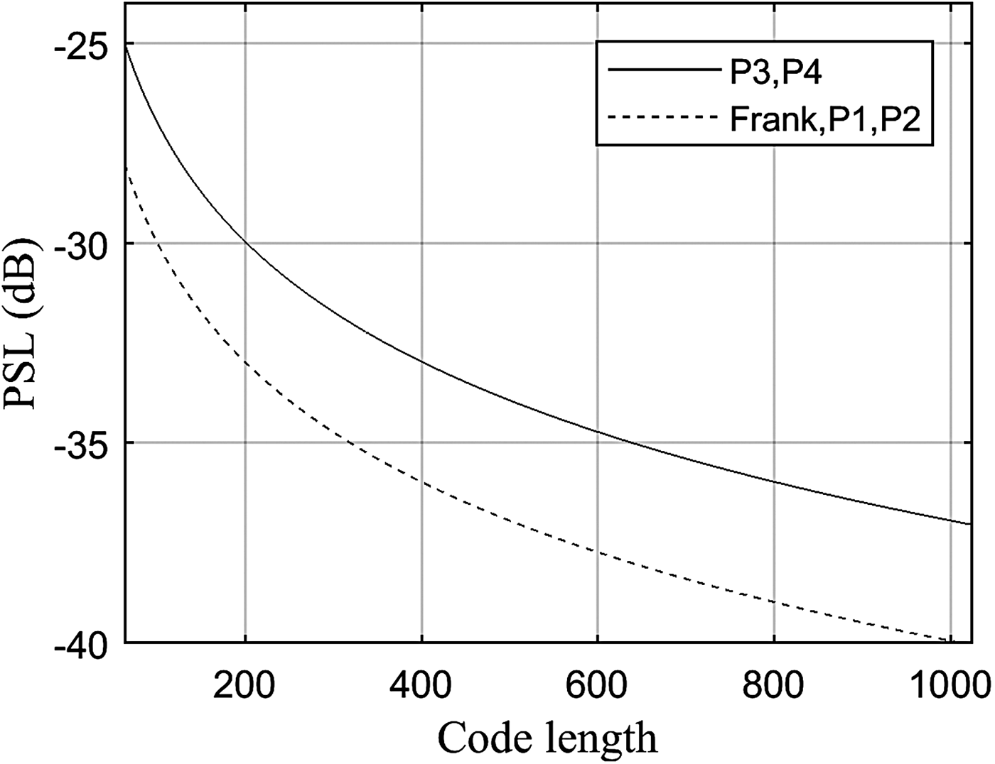
Fig. 3. PSL of polyphase coded signals.

Fig. 4. Compressed P4 pulse when fd/B = 0.07.

Fig. 5. Compressed Frank pulse when fd/B = 0.07.
The ambiguity function of polyphase coded signals has range-Doppler coupling property like that of LFM signal. Therefore, polyphase coded radars are vulnerable to the same types of deceptive repeater jammers that attack chirp radars e.g. frequency-shifting jammer and ISRJ.
Several techniques depending on time-frequency distribution are developed to detect and classify LFM and polyphase coded signals. Examples of such techniques are Choi-Williams distribution and Wigner distribution [Reference Lunden, Terho and Koivunen23, Reference Lunden and Koivunen24], where different time-frequency images are obtained for different radar waveforms. Time-frequency images are usually analyzed offline by a trained operator or by Bayesian neural networks to classify signals and extract their parameters accurately. This analysis process requires high SNR about 3 dB. In [Reference Jiang, LI and Zhao25], a new method for detecting polyphase coded signals using time-frequency rate distribution is introduced. It requires high SNR and there is no classifier for polyphase coded signals in this method.
Recently, S.B.S. Hanbali et al. [Reference Baher Safa Hanbali and Kastantin26] addressed a technique for detecting and classifying LFM signal and polyphase coded signals using optimum FrFT at low SNR where time-frequency distributions do not work. However, the performance of this technique is inferior to the matched filter. It is also shown that P3 coded signal is preferable in low probability of intercept (LPI) radars because of two reasons. First, because P3 coded signal has lower detection performance that makes it difficult to be intercepted by electronic support measures (ESM). Second, because it has high Doppler tolerance.
Orthogonal polyphase coded signals
Orthogonal polyphase coded signals are commonly used in multistatic radar systems where each system transmits a distinct signal which belongs to a set of orthogonal or non-correlated signals. In such systems, each radar detects the target not only from its return signal but also from the other radar returns. To accomplish this, each radar receiver has multiple matched filters. Each filter is matched to one transmitted signal, so multiple targets detection can be available for each radar [Reference Pace27].
Different orthogonal polyphase coded signals that have low cross-correlation, good Doppler tolerance, and low PSL are developed in [Reference Pace27–Reference Chen, Cai, Chen and Zhao33]. It is worth mentioning that orthogonal polyphase coded signals can also be used by monostatic radars. In this case, the radar successively transmits a different code chosen from a set of orthogonal signal codes to counter DRFM [Reference Deng28].
Orthogonal frequency division multiplexing (OFDM) signals
Normal modulation techniques (BPSK, QPSK, etc.,) are single carrier modulation techniques, in which the incoming information is modulated over a single carrier. Whereas, OFDM is a multicarrier modulation and multiplexing technique, which employs several carriers, within the allocated bandwidth, to convey the information from source to destination. Each carrier may employ one of the several available digital modulation techniques (BPSK, QPSK etc.)[Reference Lellouch34].
OFDM signal has some advantages such as robustness against multipath fading and relatively simple synchronization. In addition, OFDM signal is suitable for radar applications and for integrating communication functions in radar networks. It is shown that OFDM signal can easily exhibit wideband characteristics that is desirable for high-resolution radar performance [Reference Lellouch34]. However, the OFDM signal exhibits a very high peak to average power ratio (PAPR), which is only valid in linear environment conditions. Therefore, it is necessary to reduce the PAPR and use a linear amplifier with large variation [Reference Shi, Wang, Sellathurai and Zhou35].
The pulse length after pulse compression appears to have an expected value which is equal to τ pc = 1/B that makes the pulse compression ratio equals the number of subcarriers (noc) [Reference Franken, Nikookar and Van Genderen36].
The signal model which represents the OFDM radar signal is given by [Reference Franken, Nikookar and Van Genderen36]:
 $$x(t) = e^{\,j2\pi f_0t}\sum\limits_{i = 1}^N {{\rm rect}} (\displaystyle{t \over T})d_ie^{\,j2\pi f_it},$$
where f 0 is the center frequency, and the data bits d i can be any type of data representation e.g. BPSK or QPSK etc. The subcarrier frequencies are given by [Reference Franken, Nikookar and Van Genderen36]:
 $$f_i = \displaystyle{i \over {noc}}B.$$
The signal duration T is determined by the lowest frequency among the carriers [Reference Franken, Nikookar and Van Genderen36]:
 $$T = \displaystyle{1 \over {\,f_1}} = \displaystyle{{noc} \over B}.$$
Unlike pulse compression using LFM, OFDM waveform has a thumbtack like ambiguity function that does not experience range-Doppler coupling property [Reference Franken, Nikookar and Van Genderen36]. Therefore, OFDM waveforms are sensitive to Doppler shift.
In [Reference Sturm, Zwick and Wiesbeck37], it is assumed that radar processing is based on one transmitted OFDM symbol. In this case, the subcarrier spacing is limited by the Doppler frequency which has the potential to shift the alignment of the subcarriers thus destroying their orthogonality, and it can be assumed that the subcarrier spacing of Δf > 10f d,max will ensure that the orthogonality remains. The maximum unambiguous range of the radar is given by [Reference Sturm, Zwick and Wiesbeck37]:
 $$r_{{\rm max}} = \displaystyle{c \over {2\Delta f}}.$$
The radar range resolution Δr only depends on the total bandwidth occupied by the transmitted signal [Reference Sturm, Zwick and Wiesbeck37]:
 $$\Delta r = \displaystyle{c \over {2B}} = \displaystyle{c \over {2N\Delta f}}.$$
Radar and communication integrated systems using OFDM waveforms are proposed to simultaneously perform radar and communication functions on general hardware. However, the auto-correlation properties of OFDM signals have high sidelobes that depend on the transmitted information. This makes joint radar/communication systems unreliable for carrying arbitrary communication data. This problem can be overcome by transmitting fixed code sequences with special properties, which then exclude the option of transmitting information in parallel to radar sensing [Reference Lellouch and Nikookar38]. One solution to this problem is to use an OFDM radar processing approach that is proposed in [Reference Sturm, Pancera, Zwick and Wiesbeck39]. This approach does not involve correlation processing of the baseband signals but directly operates on the complex modulation symbols that compose the OFDM signal. It compares the transmitted information and the received soft-state information obtained in the receiver at the output of the OFDM de-multiplexer before performing channel equalization and decoding. Since all information symbols in one OFDM symbol are transmitted through the channel at different carrier frequencies separated by Δf, the received information symbols can be used in order to perform channel sensing at discrete frequencies. Therefore, the possibility of transmitting arbitrary information in parallel to the radar operation still exist. Furthermore, an excellent sidelobe performance that exceeds the results of the classical correlation processing approach is obtained, but the price of this performance is a loss in range resolution, by the widening of the mainlobe. Recently, a new method is proposed in [Reference Tian and Song40] to achieve high-resolution range and velocity estimation of the target under high data transmission rate in joint radar/communication system. The complete processing scheme is shown in Figure 6. The effectiveness of this method is evaluated regarding the achievable resolution on the separation of adjacent moving targets. It is seen that the two targets could be separated successfully whereas one single unresolved peak that cannot identify the two adjacent targets exist in the range profile based on matched filtering. The results demonstrate the performance advantage of the proposed processing, but it is seen that the target range slightly decreases for the high-velocity target and a worse bit error rate (BER) occurred when a larger data transmission rate was used.

Fig. 6. Improved processing scheme block diagram for radar and communication integrated systems.
Usually, OFDM scheme has good immunity against jamming. In [Reference Lellouch, Tran and Pribic41], it is shown that OFDM signal can mitigate narrowband jamming by simply turning off certain sub-bands which enable both concepts of pulse-to-pulse agility and Doppler processing to coexist in the same system. Three patterns for frequency agility are analyzed. It is shown that the random spread subcarriers pattern provides the best ambiguity function in terms of sidelobe levels and speed ambiguities compared with the random grouped subcarriers and repeated Costas grouped subcarriers. However, this pattern does not benefit from any instantaneous bandwidth reduction as the other two cases. In addition, it is shown that OFDM pulse burst supports a Doppler processing per subcarrier when the Doppler is low.
There is a potential need for radar systems to coexist with cellular radio due to the increasing demand for spectrum [Reference Huang, Bica, Mitra and Koivunen42–Reference Bica, Huang, Koivunen and Mitra44]. Joint radar and cellular communication systems shown in Figure 7 can operate in the same bandwidth without causing too much interference to each other. In [Reference Huang, Bica, Mitra and Koivunen42, Reference Bica, Huang, Mitra and Koivunen43], a multicarrier waveform is considered for both the radar and the cellular communication systems where the radar can access all the channels with a finite power constraint and interference constraints provided by the cellular communication systems. In this case, the radar constantly senses the spectrum and adapts its waveform in real time so that it uses as much bandwidth and as much power, without causing too much interference to the cellular communication systems.

Fig. 7. Joint radar and cellular base stations.
Another advantage of joint radar and cellular communication systems is to make the radar benefit from the presence of cellular communication signals for a better detection capability under the assumptions that the radar signal does not arrive at the communication base stations through a direct path, and the scattering off the target due to the communication signals arrive at the radar receiver. When the stealth target is illuminated from the front by the radar signal and from the side by the cellular communication signals. Thus, the cellular communication signals scattered off the target would be a more significant component in target detection than the radar echo. If the cellular communication signals scattered off the target are not taken into account, the detected energy is reduced. Thus, a considerably lower detection performance is obtained [Reference Bica, Huang, Koivunen and Mitra44].
Stand-off noise jamming, against joint radar and cellular base stations, shown in Figure 8 needs high-power transmission to be effective because it does not benefit from the pulse compression gain of the radar-matched filter. In addition, the gain of the radar's receive antenna in the direction of the jamming system is the side lobe antenna gain. In electronic warfare, the LPI design is an essential part of the jammer system. This is because high jamming power leads to the hostile anti-radiation missile attack. Shi et al. [Reference Shi, Wang, Sellathurai and Zhou35] addressed the problem of power allocation of OFDM radar noise jamming against a joint radar and cellular communication system, where the jammer attempts to protect the target by jamming the radar system under many assumptions, such as the radar transmitted signal, the cellular communication signal, the target impulse responses, the channel impulse responses, and the propagation losses of the corresponding channels have been intercepted and perfectly estimated. In this case, the total noise jamming power is minimized by optimizing the multicarrier jamming power allocation. Whereas, equal power allocation method has the worst LPI performance because it distributes jamming power uniformly over the whole frequency.

Fig. 8. Stand-off jamming against joint radar and cellular base stations.
Finally, it is worth mentioning that OFDM waveforms have been proposed in radar literature not only for active sensing waveforms as mentioned above, but also have been considered for passive radar, for example [Reference Berger, Demissie, Heckenbach, Willett and Zhou45].
Conclusive Remarks
The properties of each presented radar signal are summarized in Table 2. The following conclusions can be summarized as follows:
(1) LFM and polyphase coded signals are the most commonly used in different radar systems due to their high Doppler tolerance. Polyphase coded signals have an advantage over LFM due to their ability to achieve low-level time-sidelobes at the output of the matched filter without windowing, unlike LFM signals.
(2) The ambiguity function of polyphase coded signals has range-Doppler coupling property like that of LFM. Therefore, polyphase coded radars are vulnerable to the same types of deceptive repeater jammers that attack chirp radars.
(3) For PC waveform, range resolution is proportional to chip width and PSL is inversely related to the sequence length.
(4) PC waveforms have good range resolution because they used mismatched filters instead of windowing functions.
(5) The increasing demand for spectrum makes the OFDM signal to be preferable in joint radar/communication system due to its bandwidth efficiency and flexibility which is much better compared with LFM and PC signals. This is because the OFDM capability to adjust and turn on and off the individual sub-carriers for better spectrum utilization and coexistence with narrow band systems.
(6) OFDM signal does not experience range-Doppler coupling which is the main disadvantage of LFM and polyphase coded signals. Therefore, OFDM signal is less vulnerable to deceptive jammers than LFM and polyphase coded signals.
(7) OFDM signal allows independent and unambiguous range and Doppler processing. However, the auto-correlation properties of OFDM signal have high sidelobes.
(8) OFDM signals could be used in SAR, but the de-chirping technique for chirp radar cannot be used for OFDM signal due to its wide bandwidth nature which requires more computational cost of the digital signal processing [Reference Wang, Krasnov, Ligthart and van der Zwan46].
(9) The OFDM signal exhibits very high PAPR, which is only valid in linear environment conditions.
(10) NLFM, Costas, and PRN waveforms have many advantages. First, they have low PSL without using windowing functions. This leads to high-range resolution. Second, their range and Doppler measurement resolution can both be very high because their ambiguity function is an ideal ‘thumbtack’ form and therefore the measurement ambiguity will not appear. Consequently, NLFM, Costas, and PRN waveforms are less vulnerable to deceptive jammers, unlike LFM and polyphase coded signals.
(11) NLFM, Costas, and PRN waveforms have low Doppler tolerance. Therefore, they can be used when the target speed is approximately known, and can be compensated in the matched filter, otherwise, a bank of matched filters should be used.
(12) PRN waveform has some advantages over other radar signals. First, due to its random property, multiple pulses can be integrated coherently in radar receiver. Whereas, coherent integration cannot be implemented in the intercept receiver because the intercepted PRN waveform is a noise-like signal [Reference Liu, Gu, Su, Sun and Zhang47]. Second, PRN waveform is easier to generate than other waveforms, especially for large pulse compression ratio.
(13) There will be other waveforms that may be more commonly used in future radar systems. Recently, several methods are proposed to design and optimize transmit waveform and its mismatched filter simultaneously in order to suppress PSL, but the price of this performance is a loss in SNR [Reference Soltanalian, Tang and Li48]. Some of these methods take the Doppler mismatch into account [Reference Aubry, Maio and Naghsh49,Reference Wu, Song and Fan50].
(14) In fact, with nowadays technologies, radar systems are more flexible and have more processing power because of using software defined radio which is based on reconfigurable hardware. This allows the adaptive selection of the radar probe signal in the radar transmitter and the corresponding signal processing in the radar receiver, which could lead to better anti-jamming capabilities [Reference Debatty51].
Table 2. The properties of each presented radar signal

Conclusion
This paper reviewed the current research in the commonly used radar signals. It compared between them in terms of Doppler tolerance, time-sidelobe level, as well as immunity against jamming. It was shown that PRN waveform is attractive to be used in radar systems. First, because it has anti-jamming capability so it is very difficult to jam it by velocity deception. Second, because it has a high-range resolution. Third, because it achieves low PSL when a mismatched filter is used. Whereas, OFDM signal is preferable when the radar and the communication system operate in the same bandwidth because of its capability to adjust and turn on and off the individual sub-carriers for better spectrum utilization. On the other hand, the development trend of radar signals is by simultaneous optimization of transmit waveform and its mismatched filter in order to take a time-sidelobe level, Doppler tolerance, and anti-jamming capability into account. The presented results and comparison between radar signals are helpful for researchers in radar systems and electronic warfare field.
Acknowledgments
The author would like to thank Fahmi Ammareen for reviewing the final version of this paper.
 Samer Baher Safa Hanbali received the B.Sc. degree in electronic engineering from Damascus University, Syria, in 2000, the M.Sc. degree from FH-Joanneum, Austria, in 2011, and the Ph.D. degree in telecommunications from the Higher Institute of Applied Sciences and Technology, Damascus, Syria, in 2017. He works in the same institute as researcher, and his current research is focused on radar signal processing.


