I. INTRODUCTION
One challenge to consider in the design and development of medical devices is the invasiveness of the procedure. It has been shown that minimally or non-invasive treatments offer less pain, faster healing time, and even less of an effect on the bodies reaction to surgical stresses [Reference Kehlet1]. Evidence of these benefits has led to a major technological drive for more medical devices to achieve procedures usually conducted openly to minimally or non-invasive treatments. The focus of this paper is to describe the efforts in creating a device capable of delivering energy into tissue through the natural orifices for the achievement of hemostasis or the stopping of bleeding.
Such a device has a number of challenges, which accompany its design and manufacture. During a procedure, the device will be passed through the instrument channel of an endoscope to allow it to be located correctly in the upper gastrointestinal tract. This in itself provides a constraint as the device needs to fit comfortably inside the channel and allow for ease of passage and good rotation. While most endoscopes are designed to have an overall outer diameter of <20 mm due to anatomical constraints, the instrument channel is much smaller and usually varies from 7 mm down to 2.8 mm [Reference Yeung and Gourlay2].
For the device described herein, there are three major constraints or factors, which are needed to be balanced in order to create the best device. As mentioned above, the outer diameter of the device needs to be compatible with the majority of endoscopes used for procedures. Secondly, the devices’ main functionality is as an energy delivery system; it is therefore clear that the device requires a certain amount of power available at the distal tip; the theory of this will be covered briefly in a later section, but it is suffice to say that there exists a correlation between maximum outer diameter and decreased attenuation. Finally, the device makes use of a hollow channel to facilitate the delivery of liquid or to allow further functionality to be used; this creates the third constraint in which the hollow channel needs to be as large as possible. Hence, to summarize, it is required that the outer diameter is to be as small as possible, the inner hollow to be as large as possible, and the cable to have as little attenuation as possible.
A) Design considerations
As briefly covered above, the cable is required to have as little attenuation as possible. Attenuation along the coaxial cables can be described by the following simplified generic equation:
 $$\eqalign{Loss = & \left[ {27.3 \times \sqrt {\displaystyle{{\varepsilon _r} \over {\lambda _0}}} \times {\rm tan}\;\delta} \right] \cr & + \left[ {13.6\displaystyle{{\delta _s \sqrt {\varepsilon _r} \left[ {1 + (D/d)} \right]} \over {\lambda _0 D\;{\rm ln}\;(D/d)}}} \right],}$$
where the first bracketed part describes the loss due to the dielectric properties, dielectric constant, and loss tangent, and the second part describes the attenuation due to the conductive element. This second part describes attenuation not only in terms of the conductive properties of the coaxial cable, but also the geometry. D is the inner radius of the outer conductor and d is the outer radius of the inner conductor. The ratio of these two directly affect the amount of attenuation along the line.
Considering the loss a bit more, we can calculate the losses per each component of the cable itself, namely the inner and outer conductors and the dielectric. This requires us to calculate the equivalent area of each conductor, their resistance per unit length, and then the loss per component. Exemplar results from these calculations can be seen in the graph below; these results have been calculated assuming an inner conductor with outer diameter of 2 mm and varying the inner diameter of the outer conductor. Both conductors are silver, and the dielectric material has ε r of 2.1. The equations and calculations used to create this graph can be found online [3] (Fig. 1).

Fig. 1. Graph showing component attenuation with variation of dielectric thickness.
As can be seen in the graph below, the predominant contribution to loss is due to the inner conductor followed by the outer conductor and then the dielectric. It is therefore vitally important to consider the conductors both in terms of their uniformity and in terms of their conductive properties. The use of silver for the conductive material is a good choice in terms of conductive properties, but is also expensive. This problem will be discussed further on.
B) Multiple strand versus solid conductors
Braided conductors can lead to decreased conduction as a product of the proximity effect. Any current carrying metal in close proximity has its current charge confined to a smaller region, which can have an effect on the attenuation along the cables with braided conductors. It is known that the induced magnetic field can induce eddy currents in adjacent conductors and lead to the current flow being confined in the areas furthest away from other conductors carrying charge in the same direction [Reference Reatti and Kazimierczuk4]. This in turn increases the AC resistance of the cable, with some research showing evidence that a braided cable can increase its AC resistance to a level much more than its DC resistance [Reference Reatti and Grasso5]. As stated previously, a vital step in calculating the cable attenuation is to consider the resistance along the conductor. For these reasons and also in terms of maintaining a smaller outer diameter, a solid wrapped conductor was chosen. Silver is the best choice for this and once again due to the skin effect, it was possible to use a copper tape, which was then coated with a small layer of silver to save in terms of cost.
II. A NOVEL CABLE DESIGN
To achieve the discussed functionality, it was necessary to design a coaxial cable with the required dimensions, suitable attenuation, and also the implementation of a hollow center channel. It was clear that this was technically possible with reference to the skin effect, but needed some thought on how to achieve all requirements. As per the equation below, electrical conduction only takes place up to a certain depth into the conductor. Penetration depth is a function of frequency and increases as the frequency decreases [Reference Wheeler6].
 $$\delta _s = \sqrt {\displaystyle{{2\rho} \over {2\pi f\mu _0 \mu _R}}}, $$
where δ s is the skin depth, ρ is the resistivity of the conductor, f is the frequency, and μ 0 and μ R are the permeability of free space and relative permeability of the conductor, respectively.
For this device, operating at 5.8 GHz, the skin depth in silver is approximately 0.83 µm. To allow for optimal electrical conductivity while being conservative with expensive materials, a thickness of approximately 4.15 µm was utilized.
A) Initial rigid prototype designs
To initially test the theory, a rigid prototype was created. This comprised a number of polytetrafluoroethylene (PTFE) and copper tubes slotted into each other. This provided the basic coaxial structure and allowed the investigation of various methods of microwave feed and therefore energy delivery. Standard connections would impede access to the hollow channel, so various methods were considered (Figs 2 and 3).

Fig. 2. Initial prototype utilizing 90° microwave feed.

Fig. 3. Diagram showing the internal connections utilized for the 90° microwave feed prototype.
The 90° microwave feed showed promise in allowing for the delivery of energy while still maintaining access to the hollow channel. The feed geometry was calculated to act as a quarter wave transformer to match the 50 Ω generator feed to the lower impedance of the main section. While offering a good indication of the theory and providing some good ideas for progression, the rigid prototype had a few drawbacks; namely that the device was required to be flexible enough to be navigated through the digestive tract and also that the device be small enough to be located through the instrument channel of the endoscope. Due to this, further investigation was required into the materials being used.
B) Material considerations
Due to outer diameter and hollow channel constraints, the prototype materials are needed to change drastically. They are needed to be both flexible and thin enough to minimize the effect on the outer diameter of the overall device. For this reason, it was decided that a thin metal conductive wrap would be used; to achieve the desired flexibility, this would comprise a narrow strip, which is then coiled around the PTFE tube used as the inner hollow. A low-density PTFE wrap is then used as the dielectric followed by a second metallic wrap as the outer conductor. This combination allows for the standard coaxial setup, while allowing a minimal outer diameter with maximal hollow channel and dielectric thickness. Manufacturing of this was undertaken by two companies, Axon Cable and Huoer Inc.
A number of processes were considered when investigating the most suitable method for the implementation of the conductive elements. The most ideal of which would have been to adhere a thin layer of silver directly onto the PTFE tube surface. While seeming most promising, it was soon apparent that due to the low-energy non-polar surface of the PTFE and lack of van der Waals forces, achieving adhesion would be very difficult. A number of processes to achieve this were considered, including vacuum deposition and chemical methods.
C) Final design
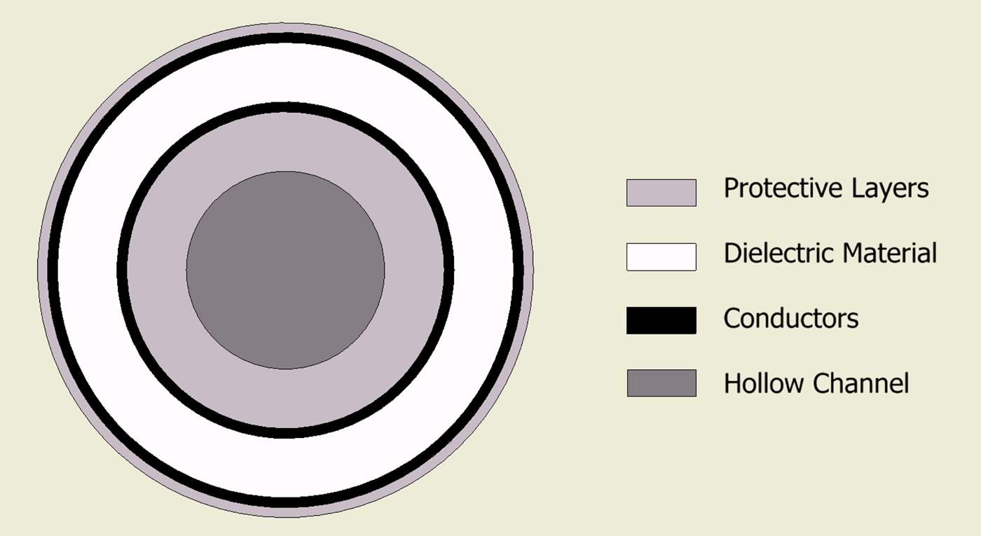
The final design comprises the following geometry. A 1.5 mm PTFE tube with wall thickness of 0.25 mm forms the hollow channel. The conductors are then comprised a silver-plated copper foil with outer diameter of 1.62 mm. The dielectric material is a low-loss, low-density PTFE wrap. The whole cable is then enclosed in an outer jacket giving a total outer diameter of approximately 2.5 mm (Fig. 4).

Fig. 4. Cross-section showing basic geometry of the new cable structure.
The combination of using the inner tube as structural support and using wrapped layers allows for the cable to have optimal flexibility while keeping the required loss characteristics. One disadvantage with the use of wrapped conductors is that it makes it more difficult to connect to, both in terms of proximal and distal terminations.
D) Variations
Once the final design had been finalized, it is relatively simple to alter the geometry to accommodate various functionality and device requirements. A smaller diameter cable has been developed and is currently under manufacture. This will allow for the device to be used deeper into the bronchial tree or in areas inaccessible with current technology. A larger diameter version is also being investigated, which would allow for larger devices or larger tools to be placed inside the hollow channel. This larger channel could accommodate multiple lumen tubing for the delivery of various liquids or gases for use in argon plasma coagulation or even to house a new complementary metal-oxide semiconductor (CMOS) sensor to allow for visualization alongside treatment.
E) Drawbacks
While the new cable design allows for the propagation of energy alongside the introduction of liquid, gas, or additional instruments, its design has a few drawbacks. Due to the geometry, namely the proximity of the inner and outer conductors, the cable deviates from the industry standard impedance of 50 Ω. While not of major concern, this needs to be considered when designing both the distal and proximal ends. The generator used for testing of this product has a 50 Ω microwave output and as such an impedance transforming structure needed to be designed and included in the device. Due to the hollow channel, a connector is needed to be designed to allow for a standard SubMiniature version A (SMA) connection to be utilized for energy delivery and also to allow unfettered access to the hollow channel. This will be discussed further in the next section.
III. PROXIMAL END CONNECTION
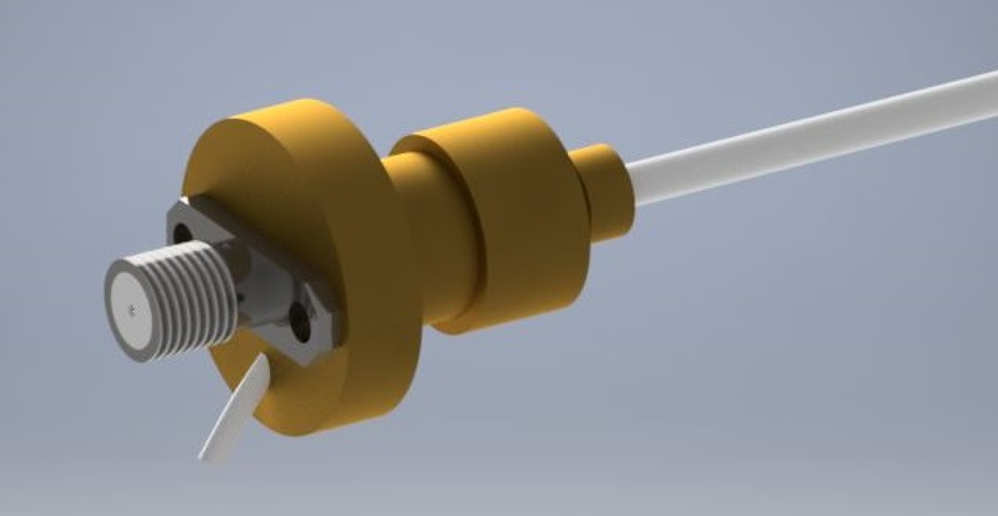
Due to the unusual impedance and access to the hollow channel, a custom connector is needed to be designed. The reflections caused by connecting a standard 50 Ω SMA connector to the cable would lead to approximately 25% power reduction. The advantage of such a connector enables the device to be easily connected and used on the majority of microwave equipment, including vector network analyzers for testing and eventually generators for actual treatment. For this reason, it has been decided that the new connector will comprise a standard SMA microwave connector coupled with a quarter wave impedance transformer. A three-dimensional (3D) render of the proximal end connection design can be seen in Fig. 5.

Fig. 5. Three-dimensional render of proximal end transformer.
A) Impedance transformation
In its current implementation, the novel cable structure has an impedance of approximately 12–14 Ω; therefore, a larger coaxial structure with a matching impedance of approximately 26 Ω was required to act as intermerdiary. The initial prototype of this structure can be seen in Fig. 6, and the individual parts can be seen in Fig. 7.
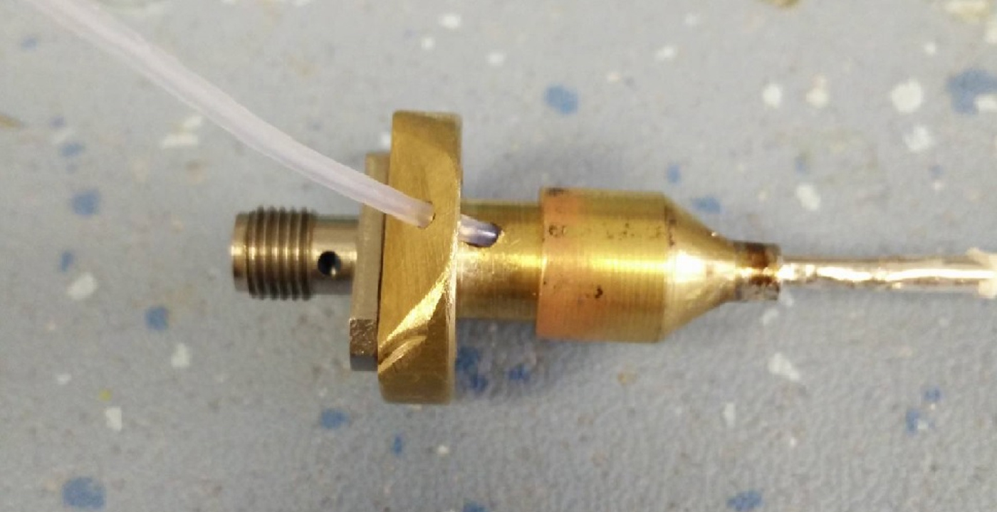
Fig. 6. Final prototype quarter wave transformer.
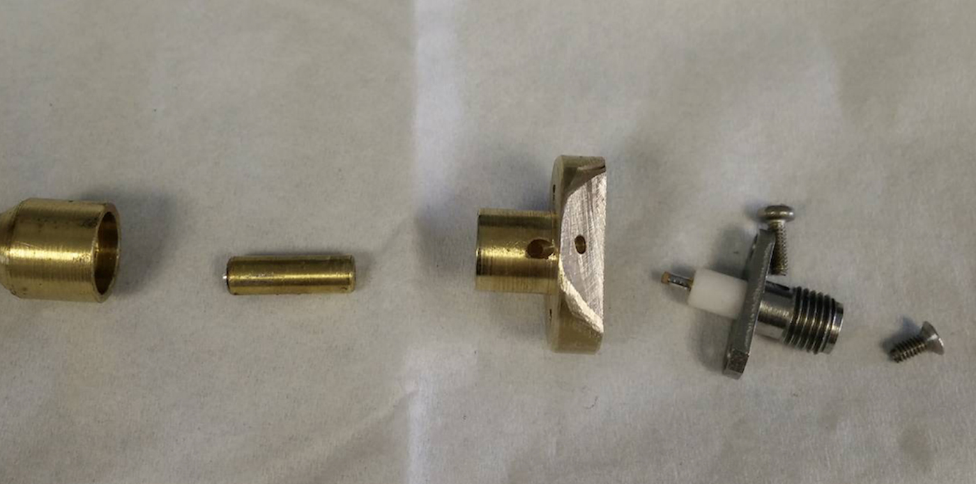
Fig. 7. The constituent parts of the transformer.
The diameters of the inner and outer conductors were calculated to provide this impedance for a length L of one-quarter wavelength at the frequency of operation, 5.8 GHz. The initial design comprises an air-filled coaxial line (ε R = 1) with the following characteristics: Z 0 = 26.5 Ω, a = 4 mm, b = 6.1 mm, and L = 12.9 mm. The transformer body is terminated to a standard 50 Ω SMA connector.
B) Access to hollow channel
While the quarter wave impedance section allows the optimal delivery of energy, it does not provide us with access to the hollow channel. It was found that passing the PTFE tube through the inner and outer parts of the transformer structure does not affect its operation. This is most likely due to the small diameter of the inner tube and due to it being non-conductive. The exposed hollow channel can then be terminated with a standard Luer Lock connection to allow the use of standard clinical syringes.
C) Handle design
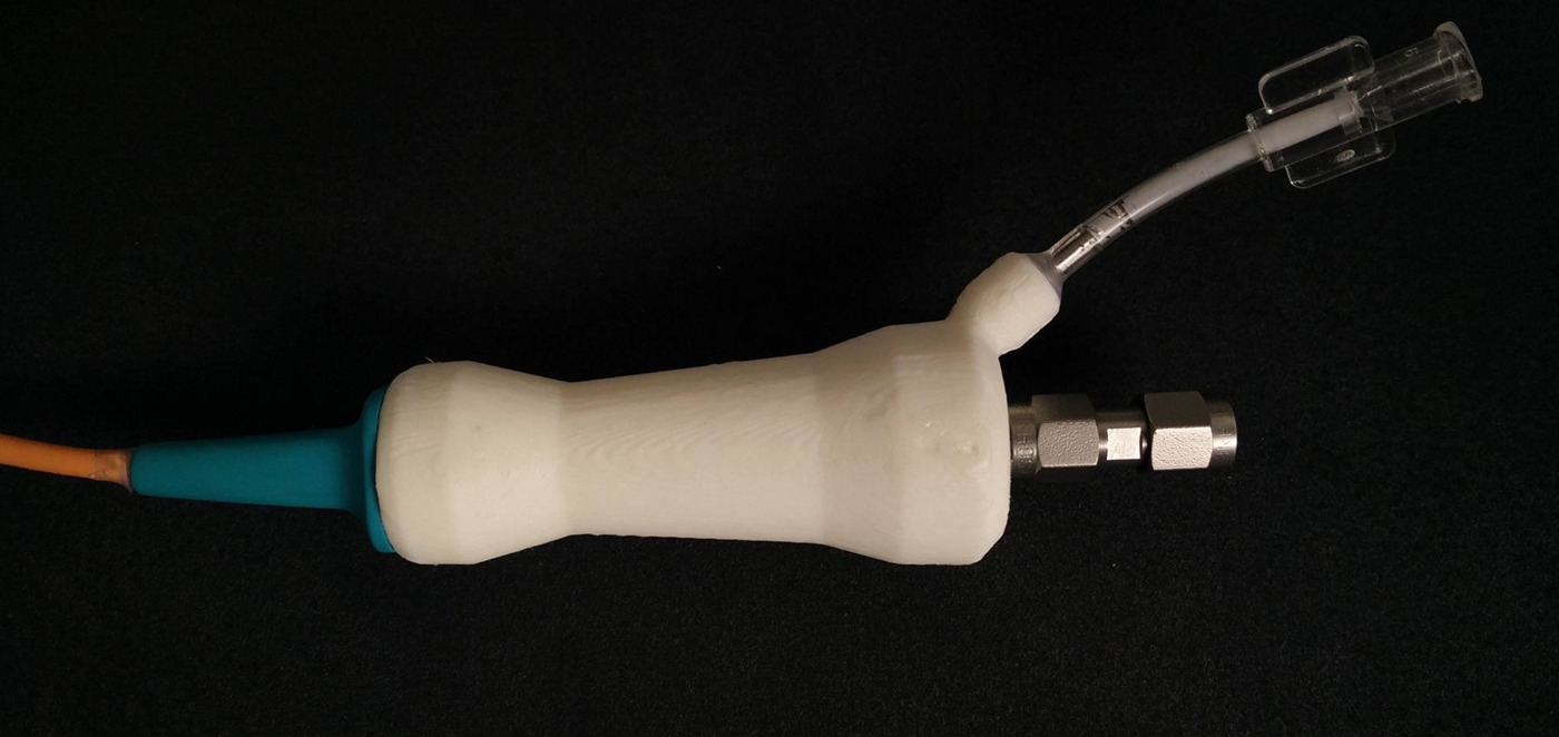
A 3D model was created in Autocad Inventor and then exported and sliced ready for manufacture. A 3D printer was used to rapidly manufacture various sizes of handle to allow all components to fit in a comfortable and ergonomic handpiece. A photograph of the final design can be seen below (Fig. 8).

Fig. 8. Photograph showing the final 3D-printed handpiece design.
IV. RADIATIVE TIP
The radiative tip needed some design consideration as a standard monopole would not be suitable for this application. The radiative tip needed to allow access to the hollow channel while providing optimal power delivery.
CST Microwave studio was used to simulate possible radiative tip designs using Macor, a machineable glass-ceramic developed by Corning Inc. Macor was chosen for this prototype due to its good thermal and electrical insulation across a range of frequencies and ease of machining. These tips were simulated radiating into a liver model, which has similiar tissue characteristics to those envisioned for use in this application. This tip embodiment flushes adrenaline out of the end of the PTFE tube in a single stream (Fig. 9). This may change dependent upon the application, where a fine mist may be more suitable. This could be achieved via the use of small micro holes to force the liquid into a spray.
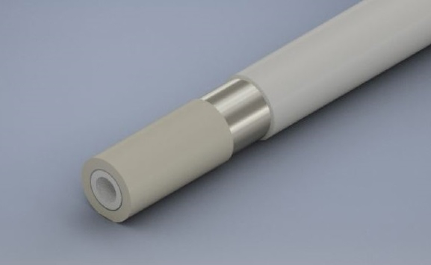
Fig. 9. Rendering of initial radiative tip design.
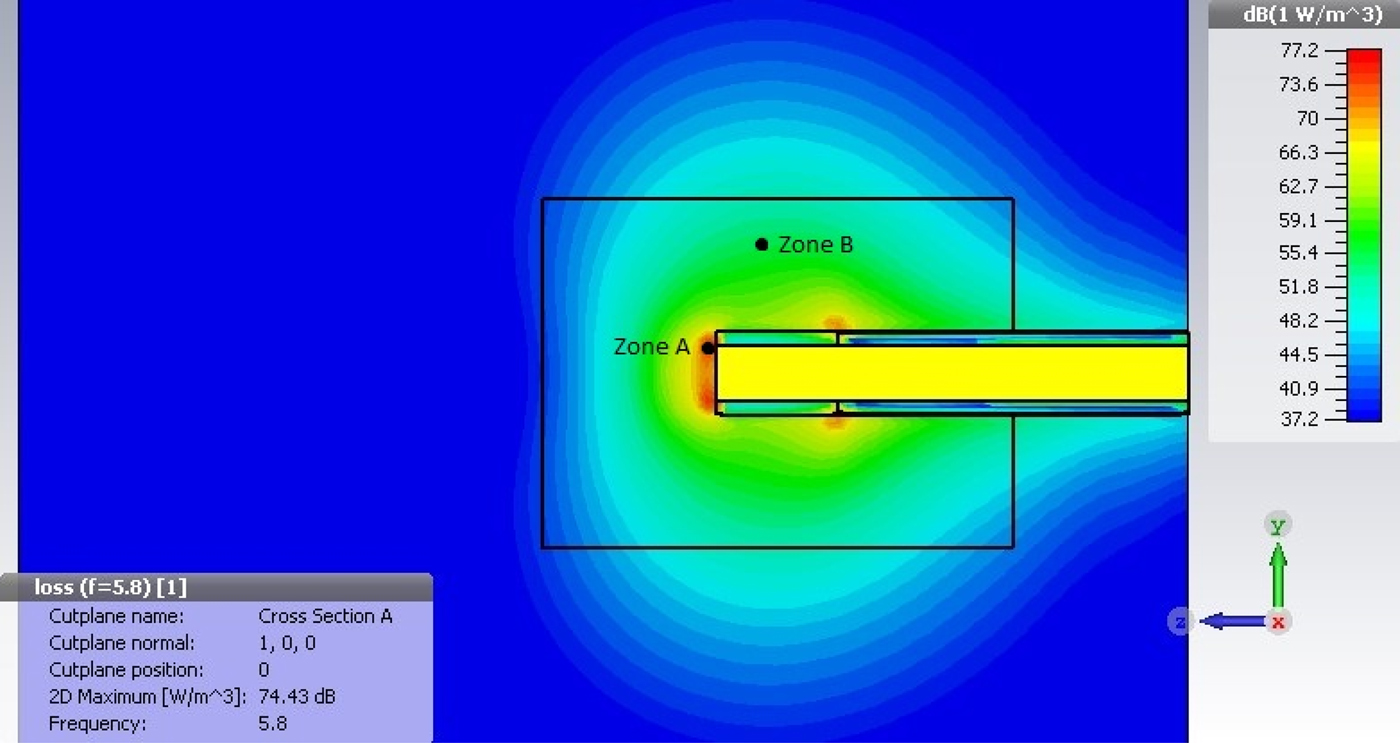
Fig. 10 shows the power density distribution of the preliminary tip design. At the distal end of the tip, a maximum power density of 74.43 dBm/m3 is found. Assuming a specific heat density of 3.49 kJ/kg/K and a tissue density of 1060 kg/m3, it can be calculated that the required energy to increase the volume of tissue by 1°C in 1 cm3 of tissue is approximately 3.7 J. To achieve coagulation, a similiar volume of tissue needs to be heated by approximately 23°C, giving a total energy requirement of about 85.1 J. As per simulation of the current design of the radiative tip, this can be achieved in 0.3 s in zone A and 8.5 s in zone B.

Fig. 10. Power density plot for Macor radiative tip.
The tip was simulated in various lengths in order to find the optimum geometry. Fig. 11 shows the return loss measurements for varying tip lengths, and it can be seen that simulated results suggest that a 3 mm tip provides the best match into tissue giving a return loss of approximately −16 dB at 5.8 GHz.
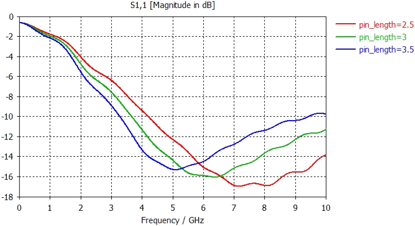
Fig. 11. Graph showing S11 return loss measurements for varying tip lengths from 2.5 to 3.5 mm.
V. CLINICAL REQUIREMENTS
Microwave usage in therapeutic medicine has increased a lot over the past decade [Reference Hancock7] and has been shown to be effective in the treatment of cancers, benign prostate hyperplasia, and endometrial ablation amongst other medical inteventions [Reference Rosen, Stuchly and Vander Vorst8]. Studies have also shown that microwave energy can provide more controlled continuous energy delivery, and therefore much higher temperatures can be achieved, much larger bleeding sites can be coagulated [Reference Yang, Converse, Mahvi and Webster9].
Rapid and effective hemostasis is one of the most crucial responses required of a surgeon during endoscopic procedures. Upper gastrointestinal bleeding accounts for over 300 000 hospital admissions annually in the USA alone [Reference Hwang10]. Intervention has been shown to not only stop bleeding, but also to prevent recurrent bleeding. This reduces the need for further surgery, minimizes further cost, and ultimately lowers mortality rates [Reference Szura and Pasternak11].
Thermal hemostasis is achieved when heat causes activation of the coagulation cascade [Reference Wara, Berg, Jacobsen, Casalnuovo and Amdrup12] usually occuring between 60 and 70°C. Mechanical hemostasis, while offering a high success rate, requires a high level of technical proficiency and precise and accurate deployment [Reference Changela13]. Injection therapies tend to be easier to use and inexpensive [Reference Kovacs and Jensen14], but offer limited coagulation and usually require a second hemostatic modality to reduce the chance of further bleeding [Reference Calvet, Vergara, Brullet, Gisbert and Campo15]. While there is little difference in incidence of rebleeding following the various procedures, there was found to be a small increase in rebleed rate following mechanical and injection therapies [Reference Hong16].
VI. IN VITRO TISSUE TESTING
Once the novel cable structure, proximal end connection, and radiative tip were connected and as a single device, a number of bench tests were carried out. Initial tests made use of standard chilled porcine liver allowed to warm up to room temperature. This was tested a few times before the actual protocol was used. The results of which can be seen above (Figs 12 and 13).

Fig. 12. Photograph showing initial bench testing 1.

Fig. 13. Photograph showing initial bench testing 2.
The following procedure was followed in order to assess the variation in power levels and the associated tissue effect:
-
1. The hemostat probe was placed onto the surface of the porcine liver model.
-
2. Mechanical pressure was applied to the chosen site to ensure constant contact with the surface of tissue.
-
3. Microwave power was delivered into the tissue at varying power levels for 5 s.
Results can be seen in Fig. 14 and Table 1. The X measurement is taken horizontally, Y vertically, and Z is the depth of penetration into the tissue. A Nardalert S3 Non-ionizing Radiation Monitor was used at all times during testing to ensure that any extraneous radiation from the tip remained well below safe-operating limits.

Fig. 14. Coagulation zone in liver: generator set to 20 W.
Table 1. Approximate coagulation zones for varying power levels.

VII. PRELIMINARY IN VIVO TESTING
Testing was carried out under laboratory conditions at St Marks hospital during a pre-clinical study. The device was used by a surgeon to achieve energy delivery into mesenteric vessels immediately following termination, while rhythmic heart movement still being present. During this test therefore, unlike in vitro tissue testing, blood was still flowing through the subject, and therefore perfusion would have played a part. The results of these tests can be seen in the figure where the coagulation zone can clearly be seen. Further testing included the delivery of adrenaline to act; in surgical procedures, this would act as a vasoconstrictor to initially stem blood flow and allow the microwave energy to be able to form a coagulated plug to seal the bleed. In this instance, the delivery of fluid was tested; due to the small diameter of the hollow channel, the force required to deliver the liquid needed to be tested.
While not a full pre-clinical study, this experiment provides a closer analog to intended usage of the device showing and provides useful results for the refinement of its design. It was also shown that smaller bleeding vessels were coagulated, stemming the flow of blood to a manageable level (Figs 15 and 16).

Fig. 15. In vivo testing photograph showing area of energy delivery.

Fig. 16. Photograph showing delivery of both adrenaline and energy.
VIII. DISCUSSION
The design and development of the new cable structure have been presented herein and have shown not only good promise both in energy delivery, but also in the ability to deliver liquid, gas, or other tooling down the hollow channel.
The simulated results for the radiative tip indicate that there is enough power being delivered into the tissue in the area of interest to initiate the coagulation cascade and achieve a good level of coagulation. It has been shown that even at the periphery of this zone, coagulation can be achieved in approximately 8.5 s for a 1 cm3 cube of tissue. While providing a good background and idea of what is required, simulation results can sometimes vary from manufactured parts either due to field changes or parasitic/capacitive changes that are not accounted for in the simulation.
In vitro tissue testing showed good coagulation across the whole power range from 10 to 40 W at the microwave source. Coagulation zone size at the lowest power was approximately 5 mm × 6 mm × 1.5 mm, which should provide enough coagulation for small vessels and small bleeding sites. One consideration in the use of in vitro porcine liver is its temperature compared with that of the tissue inside the human body; further testing might make use of heating pads or incubator to maintain the tissue at a temperature closer to body internal temperature.
Preliminary in vivo testing has shown clearly that the device can delivery enough energy to coagulate part of the mesenteric vessels and also that it is simple and easy to deliver liquid through the hollow channel.
IX. CONCLUSION
The device portrayed in this paper shows good promise as a hemostatic device for use in endoscopic procedures to prevent bleeding. Both the proximal end transformer and the radiative tip show good matching between the 14 Ω transmission line with the microwave source and the tissue, respectively. Bench tissue testing reinforced these findings and showed good coagulation was achievable through a variety of energy delivery profiles.
While in vitro testing was used to demonstrate the efficacy of the hemostatic device, further minimal in vivo testing showed promise in both the coagulation of vessels and also the coagulation of active bleeding sites. There are some alterations and refinements that could be made, such as variation of tip shape and length, to improve the matching into tissue, variation of materials, and also alternative cable structures.
ACKNOWLEDGEMENTS
The authors would like to thank Axon Cable and Huoer Inc. for their support in the development and manufacture of the cable prototypes used for the device presented herein. They would also like to thank Creo Medical Ltd. for their continued support in this project and for providing access to their equipment and expertise. All intellectual property associated with the device presented here is owned by Creo Medical Ltd.
 Shaun C. Preston graduated with first class honors in Electronic Engineering from the Bangor University in 2014 and is currently undertaking his Ph.D. degree in Electronic Engineering at the Medical Microwave Systems Research Group also in Bangor University. His main research interests include the use of microwave energy within the human body and the design of novel antenna structures to allow optimal delivery into human tissue.
 Malcolm White Received an Honours Degree in Physics from Exeter University, UK in 1977. From 1977 to 1983, he worked in the microwave tube division of the MO-Valve Company, part of GEC (UK), developing miniature magnetrons with small magnetic circuits. From 1983 to 2012, he worked in the Radar Cross Section (RCS) Department of Thales UK as a microwave engineer, trials engineer, and mathematical engineer working on most aspects of RCS measurement, prediction, analysis, and software design, as well as radar, antenna, filter, and signal processing design. From 2012, he has worked for Creo Medical Limited, designing and developing novel medical tools using microwaves.
 Brian Saunders is a Specialist Gastrointestinal Endoscopist and Luminal Gastroenterologist. His main clinical interests are the diagnosis, treatment, and prevention of intestinal diseases through flexible endoscopy. He has performed >20 000 colonoscopies and has a particular interest in therapeutic colonoscopy, especially advanced polypectomy, endoscopic mucosal resection (EMR), and endoscopic submucosal dissection (ESD).
 Zacharias Tsiamoulos currently holds the post of the Senior Clinical Researcher working under the supervision and in tandem with Professor Brian Saunders, at Wolfson Unit for Endoscopy at St Mark's Hospital and Academic Institute. His ongoing research in Luminal Gastroenterology at Imperial College, London has led to a recent appointment as a Consultant in Gastroenterology/Specialist in Gastrointestinal Endoscopy at East Kent University Hospital Foundation NHS Trust.
 Chrisopher P. Hancock received his Ph.D. degree in Electronic Engineering from Bangor University, UK in 1996. From 1997 to 2002, he was a Senior Microwave Engineer at Gyrus Medical Ltd. In 2003, he founded MicroOnclogy Ltd. to develop his ideas based on dynamic impedance matching techniques. In 2009, he was given a personal Chair in the Medical Microwave Systems Research Group at Bangor University. He is also the CTO and founder of Creo Medical Ltd.