


I. INTRODUCTION
The detection and classification of runway debris is a major concern for airport operation, as related flight delays and accident claims as well as aircraft repairs are very costly. In forthcoming years traffic on airports will even increase and thus the demand on maintaining an adequate safety level. For safe airport operation it is necessary that the runways and taxiways are permanently in an undisturbed condition. Following the recommendations of the International Civil Aviation Organization (ICAO), the inspection of runways is currently done at a period of 6 hours, visually by security personnel. This procedure is costly and may be subject to human failure and is also highly dependent on weather and daylight conditions. Especially at adverse weather the visual inspection cannot guarantee the detection of small metallic particles such as screws. Moreover, the traffic density on airports has been considerably increasing, and a secure inspection between consecutive take-offs and landings by human visual inspection is not possible.
A few automatic or semi-automatic systems have been proposed or are in use at some airports to serve this purpose [Reference Beasley, Binns, Hodges and Badley1]. Video surveillance is one of the proposals, but suffers from obscuration by bad weather. Radar sensors, which are capable to be operated under all weather conditions [Reference Patterson2], are also taken under consideration.
II. MULTI-SENSOR SYSTEM FOR DEBRIS DETECTION
The approach discussed in the following takes advantage of both sensors. Millimeter-wave radar is used for detection and pre-classification, while 2D–3D time-of-flight (TOF) cameras give additional information on detected debris, if the environmental conditions allow this.
The LAOTSE [Reference Essen, Luedtke, Warok, Koch, Schikora and Wild3] concept is based upon a net of miniaturized 220-GHz radar modules, which are positioned along the traffic areas. The 220-GHz band is used, which in comparison to lower frequencies allows considerably smaller antennas with high directivity and thus a miniaturization of the complete set-up. Furthermore, a wider bandwidth and thus a higher ranger resolution can be accommodated at higher frequencies. Using the available 220-GHz-radar modules the range of each sensor is limited to about 300 m, which allows a coverage of 1/2 km of runway. A netted approach is necessary as the output power of each radar is not sufficient to cover the whole traffic area, and additionally the probability of false alarms is considerably reduced for areas, which are monitored from different aspects. The information content of neighboring, overlapping, and in the end of all radar sensors has to be merged and aligned using overlapping segments of the surveyed area. The total LAOTSE system is additionally using distributed photonic mixer device (PMD) [Reference Ringbeck4] cameras, which are focused on objects, which have been detected by the radar and are also part of the sensor net. Figure 1 shows a sketch of the total sensor set-up.

Fig. 1. Demonstrator set-up with three radar front-ends.
III. THE RADAR CONCEPT
A) Radar geometry
Tests of an experimental LAOTSE system, with a limited number of sensors, are conducted on the Cologne-Bonn “Konrad-Adenauer” Airport (Fig. 2).

Fig. 2. Photo of Cologne-Bonn Airport with LAOTSE Site, old runway (below) and cross-wind runway.
The first LAOTSE radar module is mounted at a slightly elevated position near to the crossing of the old runway and the cross-wind runway to be able to overlook a certain area. Figure 3 demonstrates the geometry. Figure 4 shows the illumination by the antenna beam.

Fig. 3. Geometry of radar above runway.

Fig. 4. Illumination of section of traffic area by a radar module.
To miniaturize the system, the 220-GHz frequency band is used, which allows to reduce the antenna diameter by more than a factor of two. This is essential for operation in an airport environment, where obstacles like the netted sensors along the runway have to be avoided. This approach, however, demands for a wider net of sensors to cover the complete runway area. For complete demonstration of LAOTSE performance, a second sensor will be installed along the old runway to maintain an overlapping survey region. In the following, the approach for a single radar module is described.
B) 220-GHz sensor front-end
The system concept is based on a design, which was already realized at 94 GHz [Reference Essen, Wahlen, Sommer, Konrad, Schlechtweg and Tessmann5]. The radar frequency modulation continuous wave (Radar) (FM-CW) front-end uses miniaturized, monolithically integrated components in GaAs technique [Reference Tessmann6]. In order to cover a bigger range, such as 200 m, coherency of the signal is most essential. The classical FM-CW approach uses a reference signal, which is derived from a voltage controlled oscillator (VCO), which for millimeter-wave systems generally is not stable enough to maintain the necessary coherency over a range >200 m. This is due to the fact that for tuning of the oscillator the Q-factor of the resonator must not be too high, which may lead to an uncontrolled frequency drift. The drift can be so high that during the transmit–receive cycle the phase of the transmit signal has been changing so much that the mixing of reference and receive signal does not result in a sharp frequency response but to a widening of the receive signal. This widening increases with range and at a certain range limit no sufficient range resolution can be achieved. As this concept does not allow to guarantee a sufficient range, at least phase locking of the VCO is necessary or, even better, a DDS-based concept, such as that shown in the block diagram of Fig. 5, has to be used. The output frequency is shifted to 105 GHz instead of 94 GHz and a subsequent doubling results in an operating frequency around 210 GHz reference- and receive signals.

Fig. 5. Block diagram of 220-GHz LAOTSE radar.
All system frequencies are generated or derived from a stable crystal oscillator. A dielectric, resonator stabilized oscillator generates the reference frequency of 17.2 GHz upon which the radar waveform, a linear FM-chirp with a bandwidth of 220–380 MHz is mixed. A multiplication by a factor of 6 leads to a basic millimeter-wave frequency band of 104.52–105.48 GHz. After amplification this signal is split into the transmit branch and the local oscillator branch. The latter is used for down-conversion of the receive signal using a subharmonic mixer. The transmit signal is derived by doubling to result in a frequency band of 209.04–210.96 GHz, a total bandwidth of 1.92 GHz, equivalent to a range resolution of about 8 cm.
The RF front-end is quite compact and avoids long waveguide connections. Figure 6 shows a photo.

Fig. 6. Photo of a 220-GHz LAOTSE radar front-end.
The complete radar RF part is mounted within the primary focus of the antenna. IF and DC connections to the data acquisition and control box are maintained by rotary joints leading through the center of the antenna pedestal.
For the first experiments a self-contained steering and data acquision box was developed, which is capable of operating a single LAOTSE sensor, in order to store the measured radar and distribute all relevant data into the sensor network. For the operational system only a miniaturized data-interface box will be assigned to each radar sensor. An field programmable gate array and fast fourier transform (FPGA)-based processing electronics will deduce high-resolution range profiles by applying an fast fourier transform (FFT) algorithm, which contain the information on RCS and position of debris objects, and which serve as a basis for further netted processing and the change detection algorithm.
C) Antenna and pedestal
As the FM-CW principle is used for the LAOTSE radar, special care has to be taken for a good isolation between receiver and transmitter, which is essential for a good dynamic range of the system. For an optimum performance, separated antennas were used. To allow a wide operation bandwidth, which is necessary for a high range resolution, offset feed antennas were used. To avoid long waveguides serving the two antenna feeds, a design as shown in Fig. 7 was used.

Fig. 7. Sketch of antenna assembly and photo of radar upon pedestal.
Each radar module is mounted on an antenna pedestal capable of surveying 360° angular region in azimuth and +20° in elevation. During operation the elevation is fixed according to the geometrical conditions. Figure 7 shows also a photo of a radar module on its pedestal.
IV. OPTICAL SYSTEM
A) ToF system concept
ToF camera systems, as the name suggests, are able to measure the distance between the camera and a reflecting point by measuring the elapsed time. Hence, ToF is – quite similar to a radar – an active ranging system that needs an illumination source. Basically, a ToF camera emits continuously a light signal with a constant wavelength. Mostly, the near-infrared area is used for this purpose, because it is invisible and simultaneously not harmful for the human eye (Fig. 8).

Fig. 8. PMD CamCube consisting of camera and illumination unit.
To measure distances, the light has to be modulated adequately. Then, it is possible to evaluate it as the modulation of the back-scattered signal differs from that of the emitted one. ToF cameras usually modulate their carrier signal by a harmonic oscillation with the frequency f. Then, the phase difference is given by
where R denotes the distance between transmitter and reflecting object and c is the speed of light. Transmit and receive signals are mixed for each individual pixel of the sensor matrix that allows the determination of the phase difference, i.e. by sampling of the obtained correlation function at four time samples with the values A 1, A 2, A 3, A 4 each shifted by 90° [Reference Ringbeck, Schaller and Profittlich7]:
Then, the range is calculated by (1). If the modulation frequency is stable enough, the integration time can be chosen comparably high to improve the signal-to-noise ratio. However, the choice of the modulation frequency f is crucial as it directly constraints the maximum range. Only phase differences of 0 ≤ Δφ < 2π within one period can be used for
Commercial ToF cameras often operate with a modulation frequency of 20 MHz, yielding a 7.5-m-long measurement area. In order to increase this, signal processing techniques, as known from image processing for radar interferometry, can be applied to evaluate the phase information of adjacent pixels. Such 2D phase unwrapping methods allow an unambiguous phase determination over multiple periods [Reference Ringbeck and Hagebeuker8]. Another option would be to use multitone techniques as they are known from automotive applications [Reference Fatihi, Hantscher, Rubart, Krebs, Nüßler and Essen9]. An overview about the technical specifications is given in Table 1. The camera lens is changeable and thus customized for different applications, such as for automotive applications, long-range surveillance, or medical applications (short-range surveillance).
Table 1. Performance parameter of PMD camera.

V. TEST MEASUREMENTS
A) Inverse synthetic aperture (ISAR) measurements at 220 GHz
To test the sensitivity of the system and to evaluate the range under which small items can be detected, measurements with an assembly of 25 different small objects on a turntable at a range of about 200 m were conducted. The objects were turned over 360°, and the measured data were evaluated using an ISAR algorithm, which, in contrary to the final LAOTSE algorithm gives a synthetic radar image of each object. Table 2 gives a catalogue of the measured objects. Figure 9 shows a photo of the assembly of parts on the turntable.

Fig. 9. Test objects on turntable.
Table 2. Sample objects used for ISAR measurements.

Before the measurements, the system was calibrated by means of a trihedral corner reflector, which was positioned in the middle of the turntable. This allows a thorough phase calibration, which is necessary for the ISAR process and at the end allows to assign a distinct radar cross section to each item on the turntable. Figure 10 shows ISAR images for an aspect angle range of 360 and 10°. The latter is less than typical for the LAOTSE geometry. The evaluation showed that all small items could be detected and imaged independent of aspect angle. Only for dry wooden blocks this did not apply, as they could be seen only at those angles, where they were facing the radar. If they were only a little bit humid, they were also visible for all aspect angles. Resolution does not play an important role and the detectability is not influenced by a resolution range between 2 and 8 cm. It can be concluded that for an operational system a resolution of about 10 cm is fully sufficient.

Fig. 10. ISAR image of sample objects for 360 and 10° aspect angle range.
B) LAOTSE radar measurements
While for the test measurements, described above, the radar was fixed and the objects were turning to be visible for all aspect angles; further tests were conducted with the operational geometry of a scanning radar. By chance the weather was very bad with low visibility during the measurements. Figure 11 shows a photo of the measurement scene. Figure 12 shows the result of a sector scan. Clearly, the fence surrounding the terrain can be identified by its very strong radar echo (red) and the returns of some small items in front of the fence.

Fig. 11. Measurement scene at Fraunhofer FHR.
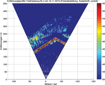
Fig. 12. Sector scan for test scene.
C) Measurements with the PMD camera
The combination of radar technology and optical systems facilitate a reliable surveillance of runways. To demonstrate this, a ToF camera from PMD Technologies GmbH was used to image different objects and materials on a smooth plane. To demonstrate the potential of such a ToF system, a 870-nm PMD camera comprising of about 200 × 200 pixels was used to image different objects and materials, as demonstrated in Fig. 13.
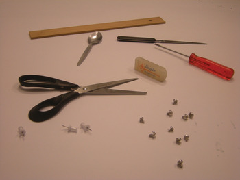
Fig. 13. Sample assembly of small objects for PMD camera tests.
To obtain detailed and undistorted images a free-space measurement has to be carried out with the camera system, which will be subtracted from the following measurements. This is a similar idea as for the surveillance radar, which detects objects using change detection methods. Only deviations from frame to frame in the signature of the surface of the runway are imaged. Thereby the range increase in dependency of the aspect angle, as well as the intensity variation within the illumination spot can be removed.
Different objects and materials have been imaged. The objects can be identified easily by their shape. This allows a reliable evaluation of the threat on the runways by the airport personnel which can decide, whether a removal is mandatory or not as in the case of a non-dangerous item such as a piece of paper. As described in the section above, ToF cameras are able to measure 3D objects. To illustrate this, the scissors from the test set-up in Fig. 13 have been selected exemplarily. Figure 14 shows the result. The height information is coded by the red color. The bars as well as blades are depicted in a clear way, such that the item can be identified as scissors. The range deviation could be compensated successfully as the object is imaged on a constant elevation. It should be mentioned that both measurements can also be carried out under foggy or rainy conditions making the system very attractive for a non-stop operation.

Fig. 14. 3D image of the scissors from Fig. 13.
VI. SENSOR DATA FUSION
The miniaturization of the antennas leads to a netted setup of multiple radars to cover the whole runway. The detection of foreign object detection (FOD) is done by change detection separately for each sensor. The geometric data fusion between all netted sensors could be done using the position and attitude of each sensor. In this approach the position and attitude must be exactly known, to treat them correctly in a geometric transformation process. To overcome this limitation the overlap regions between the sensors can be used. The relatively high resolution of the sensors allows to treat the radar data as images. Adjacent radars produce images with an overlap region. With this region a matching in the image plain can be performed. The first step is to detect feature points in every radar image. Possible feature detectors are the Harris detector [Reference Harris and Stephens10] or the scale invariant feature detector [Reference Lowe11]. These feature points can be matched to another. With these matches an affine transformation between two images can be computed. This procedure can be easily scaled to an arbitrary number of sensors. The benefit of this approach is the independence of the sensor geometry. In comparison with the first approach, only the position and attitude of one sensor is needed to project the detection result on the runway, while the position and attitude of the other sensors can be unknown.
The overlap region can be also used to improve the detection results. It may occur that the radar cross section of an FOD is so small that it is not detected through the change detection. If this happens in an overlap region, then it is highly possible that it can be detected by its adjacent sensor. This can also decrease the false alarm rate of the system and increase its probability of detection.
VII. CONCLUSIONS
An innovative solution for runway surveillance and debris reconnaissance was proposed. Millimeter-wave radar sensors as well as optical 3D sensors were fused to get as much information as possible and to achieve a high and reliable detection rate. The system supports the airport personnel responsible for the safety of aircrafts on runways during take-off and landing by giving an alarm in the case of a dangerous item on the runway. Radar modules at a frequency of 220 GHz were developed as elements for a netted set-up along traffic ways on airports. It was demonstrated that also under adverse weather conditions small objects, metallic and non-metallic, could be detected. The radar system monitors the runway in change detection mode and gives the fused information to the optical system that images the item in more detail. Test measurements showed the feasibility of this technique by using a ToF camera. Both the intensity plot as well as the 3D range image enabled a clear identification of objects.
ACKNOWLEDGEMENTS
The project is financed by the Ministry for Innovation, Science and Technology of the German Federal State of North-Rhine Westphalia under the ZIEL2 Program of the European Fund for Regional Development (EFRE).
 Helmut Essen graduated in Physics and received his Ph.D. both from the University of Bonn in 1972 and 1976, respectively. After his post-doc time at Max-Planck-Institute for radio astronomy he joined FGAN-Research Institute for High Frequency Physics and Radar Techniques in 1977. There he was engaged with millimeter-wave radars doing research on radar signal-processing, propagation of radio waves and terahertz imaging. Since 1995 he is heading the department of millimeter-wave radar and high-frequency sensors, at Fraunhofer Institute of High Frequency Physics and Radar Techniques. He is co-author of books on remote sensing and author of more than 200 scientific papers. He is a member of the German Physical Society (DPG), the German Terahertz Center, the European Microwave Association (EuMA) and senior member of the IEEE Geoscience and Remote Sensing Society. He is a member of the national advisory board on Microwave Technology of the ITG/VDE.
 Sebastian Hantscher received the Dipl.-Ing. degree from the Dresden University of Technology in 2004, Dresden, Germany. From 2005 to 2008, he has been with the Johannes Kepler University in Linz, Austria, where he served as a lecturer as well as researcher on signal processing, radar imagery, and hardware concepts for ultra-wideband radar systems. In 2008 he received the Dr. techn. degree with distinction. In 2009, he joined Fraunhofer FHR in Wachtberg, Germany. His research interests currently include multistatic radar concept engineering for security applications, especially at millimeter-wave frequencies, as well as synthetic aperture radar processing. Dr. Hantscher is working as a reviewer of several scientific journals and is a member of the IEEE MTT Editorial Review Board. He authored and co-authored more than 40 scientific papers.
 Martin Schröder received his Dipl.-Ing.(FH) degree from the Bonn-Rhine-Sieg University of Applied Sciences in 2005. From 2006 to 2010 he studied at the distance teaching university of Hagen and received his M.Sc. degree in 2010. In 2002 he joined Fraunhofer FHR in Wachtberg. He is involved in the engineering of millimeter-wave radars for security applications and radar signal processing. He is a member of the European Microwave Association (EuMA).
 Wolfgang Koch studied Physics and Mathematics at the Technical University Aachen. At present, he is head of the department “Sensor Data and Information Fusion” at Fraunhofer FKIE, a research institute active in defence and security, mainly for the German Ministry of Defence. On fusion topics, he published several handbook chapters and numerous journal/conference articles. For the IEEE Transactions on Aerospace and Electronic Systems (T-AES), he serves as an Associate Editor-in-Chief and Technical Editor for Target Tracking and Multisensor Systems. Moreover, he is member of the Board of Directors of the International Society of Information Fusion (ISIF). At Bonn University, he holds a habilitation degree on “Applied Computer Science” and gives regularly lecture series on Sensor Data and Information Fusion. He initiated a series of the annual IEEE workshops “SDF: Sensor Data Fusion: Trends, Solutions, Applications.” In 2010, he has been elevated to the grade of Fellow of the IEEE.
 Goert Luedtke studied Chemistry at the University of Bonn, Germany. At present, he is project and business development manager of the department “Sensor Data and Information Fusion” at Fraunhofer FKIE, a research institute active in defence and security, mainly for the German Ministry of Defence.
 Marek Schikora received a B.S. (Vordiplom, 2006) and the M.S. (Diplom, 2008) in Computer Science from the University of Bonn, Germany. Since 2009 he is a research scientist in the Sensor Data and Information Fusion department at Fraunhofer FKIE. In addition, he is a Ph.D. student at the Computer Vision Group at the Technical University of Munich, Germany. His research is focused on sensor fusion, multi-target tracking, and related computer vision topics, such as image segmentation, object detection, and classification.
 Paul Warok received his Dipl.-Ing.(FH) degree in Information Technology from the University of Applied Sciences in Bielefeld in 2009. In October 2007 he joined Fraunhofer FHR in Wachtberg. There he is involved in the development of different millimeter-wave radars for security applications and material analysis systems. The development includes design of radar systems, creating PCB layouts, prototyping of PCBs with Laser prototyping systems, simulation of various RF structures in Ansofts HFSS and measurement and testing of radar systems.
 Rüdiger Zimmermann received his Dipl.-Ing.(FH) Degree in 1991 from the Aachen-Juelich University of applied Science. From 1991 to 2003 he worked on the Development of Submm-wave Oscillators and Radiometers. Since 2008 he is employed at the Fraunhofer FHR. He is involved in the development of Submm-wave radar frontends for security applications.


