Introduction
With the development of wireless communication, sensing, and radar systems, demands for low-cost circuits and transceivers that can support multi-band and multi-mode operation are increasing rapidly [Reference Wolf, Joram, Schumann and Ellinger1–Reference Jain, Tzeng, Zhou and Heydari8]. As a key component of dual-band transceivers, dual-band mixers deserve in-depth study.
Several dual-band fundamental mixers (FMs) with dual-band impedance matching networks have been developed under 6 GHz [Reference Abdelrheem, Elhak and Sharaf9–Reference Hwang, Yoo and Yoo11]. However, it is difficult to implement local oscillators (LOs) with low phase noise and wide turning range at millimeter-wave (MMW) frequencies. By either mixing the input signal with the fundamental or higher-order harmonic component of the LO, dual-band performance can also be achieved [Reference Jackson and Saavedra12, Reference El-Nozahi, Amer, Sánchez-Sinencio and Entesari13]. The mixers, which can be reconfigured between fundamental and subharmonic modes by changing the LO waveforms [Reference Mazzanti, Vahidfar, Sosio and Svelto14] or the bias conditions [Reference Zhu, Wang and Wu15], have also been proposed for dual-band operation. In addition, an MMW dual-band switchable star mixer was also proposed by changing the effective length of the Marchand baluns [Reference Wang, Hou, Chen and Hong16]. However, these mixers can operate only in one band at a time, which are not suitable for concurrent dual-band applications [Reference Hashemi and Hajimiri17–Reference Zhang, Hasan, Ghannouchi, Helaoui, Wu, Yu and Liu20].
In this paper, a fundamental and subharmonic hybrid CMOS mixer is proposed for MMW dual-band applications. Based on a hybrid structure with two switching quads and a quasi-diplexer, this circuit can function either as an FM or a subharmonic mixer (SHM). In addition, the hybrid mixer can operate at two MMW bands concurrently as long as the frequency conversion schemes are carefully designed.
Circuit design and analysis
Figure 1 shows the schematic of the proposed MMW CMOS hybrid mixer. It consists of two switching quads (M 1–M 8), equipped with 20-μm width transistors biased at VGS = 0.4 V. The selection of device size and bias voltage was made to obtain a maximum conversion gain (CG) following the procedure presented in [Reference Kodkani and Larson21]. Herein, the voltage VS (as shown in Fig. 1) is set to 0 V for simplicity, which can be set to other values to bias the baseband amplifiers in future work. Because there are no DC current paths for the transistors, the drain–source voltage (VDS) of the transistors is 0 V. Different from conventional SHMs [Reference Kodkani and Larson21, Reference Jen, Rose and Meyer22], an additional “quasi-diplexer” formed by CB 1, CB 2, CF 1, CF 2, LF 1, and LF 2 is inserted between the switching quads to establish a hybrid structure with two down-conversion paths (as shown in Fig. 1) for dual-band applications. The quasi-diplexer has a low-pass characteristic in path 1 and a high-pass characteristic in path 2. The values of CF 1, CF 2, LF 1, and LF 2 are chosen to make the cutoff frequency of the low-pass filter (LPF) higher than the IF frequency (fIF), whereas the values of CB 1 and CB 2 need to be small enough to block the IF signal in path 2. Three Marchand baluns are used to generate differential RF and LO signals [Reference Zhu, Wang and Wu15, Reference Zhu, Wang and Wu23]. A 90° coupler and an inductor (LC) are jointly used to provide an optimum LO phase distribution for the switching quads.

Fig. 1. Schematic of the proposed MMW CMOS hybrid mixer.
Assuming the two switching quads are driven by two phase-shifted square-wave LOs with a 50% duty cycle and the transistors are operating as ideal switches, the voltage across AA′ (as shown in Fig. 1) can be expressed as [Reference Zhao, Öjefors, Aufinger, Meister and Pfeiffer24]:

where fLO is the LO frequency, VRF and fRF are the voltage amplitude and frequency of the RF signal, respectively.
Subharmonic mixing mode
For fRF = 2fLO ± fIF, where fIF is the IF frequency, the lowest frequency in (1) is fLO − fIF. Because fLO is much higher than fIF in MMW applications, all the frequency components in (1) will be blocked by the LPF in path 1, because the cutoff frequency of the LPF is much lower than fLO − fIF. Therefore, they can only be passed to BB′ (as shown in Fig. 1) for the second stage of mixing and the subharmonic mixing is obtained in path 2.
Theoretically, the best CG performance is achieved when the LO1 and LO2 are in quadrature [Reference Kodkani and Larson21, Reference Jen, Rose and Meyer22]. In practical, however, the optimum LO phase shift will drift away from 90° due to the parasitic effects of the transistors at MMW frequencies [Reference Zhao, Öjefors, Aufinger, Meister and Pfeiffer24] and the existence of the quasi-diplexer. Figure 2 illustrates the impact of the parasitic effects of the transistors and the existence of the quasi-diplexer on the simulated CG performance. For the SHM without the quasi-diplexer, the optimum LO phase shift drifts from 90 to 70° when the LO frequency moves from 0.24 to 24 GHz, due to the parasitic effects of the transistors [Reference Zhao, Öjefors, Aufinger, Meister and Pfeiffer24]. Meanwhile, the maximum CG is decreased significantly because the modulating currents in the mixer find a path to ground through the substrate resistance and the parasitic source–bulk and drain–bulk capacitances at higher frequencies [Reference Kodkani and Larson21]. By adding the quasi-diplexer, the optimum LO phase shift further drifts from 70 to 60° at 24-GHz LO frequency, because the quasi-diplexer introduces additional phase delays for the frequency components in (1). In addition, the maximum CG is further decreased by 1.9 dB due to the insertion loss of the quasi-diplexer. Figure 3 shows the simulated CGs of the proposed SHM with respect to LO phase shift for different LO frequencies. As can be observed, the optimum LO phase shift is 85, 70, 60, and 55° for the LO frequency of 16, 20, 24, and 28 GHz, respectively. In this study, the LO phase shift of 60° is chosen, so that the CG is close to the peak value for the LO frequency of 20, 24, and 28 GHz, respectively, whereas the CG is only 0.8 dB lower than its peak value for the LO frequency of 16 GHz.

Fig. 2. Impact of the parasitic effects of the transistors and the existence of the quasi-diplexer on the simulated CG performance.

Fig. 3. Simulated CGs with respect to LO phase shift for different LO frequencies.
To achieve 60° of LO phase shift, a 350-pH inductor LC is inserted between the 90° coupler and the LO balun 2. Figure 4 compares the simulated CGs of the SHM with and without LC. By introducing the inductor LC, the CG of the SHM is improved significantly at high LO frequencies but a little degraded at low LO frequencies. In future work, the optimum LO phase distribution can be implemented by investigating a novel coupler with arbitrary phase shift.

Fig. 4. Simulated CGs of the SHM with and without the inductor LC.
Fundamental mixing mode
For fRF = fLO ± fIF, the lowest two frequencies in (1) are fIF and 2fLO − fIF. Because the IF signal is blocked by the capacitors CB 1 and CB 2 in path 2, it can only be passed to the IF1 port through path 1. Meanwhile, because the cutoff frequency of the LPF is much lower than 2fLO − fIF, all the frequency components in (1) except for the IF signal will be filtered by the LPF. Therefore, only the IF signal is passed through path 1 and the fundamental mixing is obtained in path 1.
Concurrent mixing mode
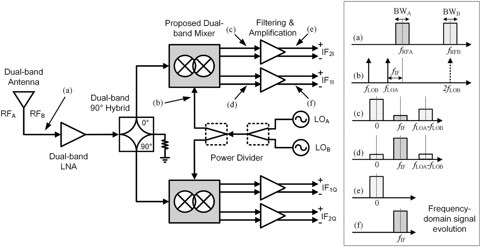
By carefully assigning the LO frequencies, the proposed hybrid mixer can also function as a concurrent dual-band mixer. For instance, Fig. 5 shows an application of the hybrid mixer in a concurrent dual-band receiver that is capable of simultaneous operation at two different frequencies (fRFA and fRFB) by imposing the following conditions: (1) fLOA = fRFA − fIF, (2) fLOB = fRFB/2, (3) fIF > (BWA + BWB)/2, and (4) |fLOA − fLOB| > fIF + (BWA + BWB)/2. The frequency domain signal evolution in the concurrent dual-band receiver is also illustrated in Fig. 5. The proposed concurrent dual-band receiver can be viewed as a low-IF receiver for the signal of RFA and a subharmonic direct-conversion receiver for the signal of RFB. Therefore, both the receiver architectures have the advantage of low DC offsets [Reference Jen, Rose and Meyer22, Reference Crols and Steyaert25]. In addition, the flicker noise issues in low- and zero-IF CMOS receivers can also be mitigated by using passive mixers [Reference Redman-White and Leenaerts26–Reference Wei, Meng, Wu and Tsung29].

Fig. 5. An architecture for concurrent dual-band receiver.
Experimental results
The proposed MMW hybrid mixer is fabricated using a standard TSMC 65-nm CMOS process. The photo of the chip is shown in Fig. 6 with a chip size of 0.69 × 0.73 mm2, including all pads and dummy metal. The mixer was measured via on on-wafer probing.

Fig. 6. Photo of chip of the proposed MMW hybrid CMOS mixer.
The measured and simulated CGs versus LO power level (fLO = 24 GHz, fIF = 100 MHz) for both SHM and FM modes of the mixer are shown in Fig. 7. It is observed that an LO power of 10 dBm is required for the SHM. Figure 8 shows the measured and simulated CGs versus RF frequency for both modes of the mixer. The maximum CG of the mixer is −13.7 and −7.6 dB for the SHM and FM modes, respectively, the 3-dB RF bandwidth is from 30 to 53 GHz and 16 to 35 GHz for the SHM and FM modes, respectively. The measured CGs of this mixer are considerably lower than that in [Reference Zhu, Wang and Wu15], due to the following reasons: (1) the lack of IF buffers, which provide about 7-dB power gain in [Reference Zhu, Wang and Wu15]; (2) the transconductance (gm) of the transistors is lower than that in [Reference Zhu, Wang and Wu15] due to VDS = 0 V; (3) the quasi-diplexer also introduces 1.9-dB additional insertion loss, as shown in Fig. 2. The measured 3-dB IF bandwidth is 1.2 and 1.5 GHz for the SHM and FM modes, respectively. The measured LO-to-RF and 2LO-to-RF isolations are better than 40 and 58 dB, respectively, as shown in Fig. 9. The measured input 1 dB power compression point (IP 1dB) of the mixer is 4 and 6 dBm for the SHM and FM modes, respectively. A performance summary and comparison to other dual-band MMW mixers are shown in Table 1.

Fig. 7. Measured and simulated CGs versus LO power for both subharmonic and fundamental modes.

Fig. 8. Measured and simulated CGs versus RF frequency for both subharmonic and fundamental modes.

Fig. 9. Measured LO-to-RF and 2LO-to-RF isolations.
Table 1. Comparison of MMW dual-band mixers

Conclusion
In this paper, a millimeter-wave (MMW) fundamental and subharmonic hybrid dual-band CMOS mixer is proposed and presented. Based on a hybrid structure with two switching quads and a quasi-diplexer, the proposed mixer can function as an FM or a SHM. In addition, the hybrid mixer can also operate at two MMW bands concurrently as long as the frequency conversion schemes are carefully designed. This is very appealing for MMW systems to reduce the system size, increase the versatility, and/or extend the available bandwidth.
Acknowledgement
This work was supported by in part by the Natural Science Foundation of China under Grant 61901147 and in part by the Qianjiang Talent Project Type-D of Zhejiang under Grant QJD1902012.
 Fang Zhu received his B.S. degree in electronics and information engineering from Hangzhou Dianzi University, Hangzhou, China, in 2009, and his M.S. and Ph.D. degrees in electromagnetic field and microwave technique from Southeast University, Nanjing, China, in 2011 and 2014, respectively. From 2014 to 2016, he was a MMIC Designer with Nanjing Milliway Microelectronics Technology Co., Ltd., Nanjing, China. From 2016 to 2019, he was a Postdoctoral Research Fellow with the Poly-Grames Research Center, Polytechnique Montréal, Montréal, QC, Canada. He is currently a Professor with the School of Electronics and Information, Hangzhou Dianzi University, Hangzhou, China. His current research interests include microwave and millimeter-wave integrated circuits, components and transceivers for wireless communication and sensing systems.
 Guo Qing Luo received his B.S. degree from the China University of Geosciences, Wuhan, China, in 2000, his M.S. degree from Northwest Polytechnical University, Xi'an, China, in 2003, and his Ph.D. degree from Southeast University, Nanjing, China, in 2007. Since 2007, he has been a Lecturer with the faculty of School of Electronics and Information, Hangzhou Dianzi University, Hangzhou, China, and was promoted to Professor in 2011. From October 2013 to October 2014, he joined the Department of Electrical, Electronic and Computer Engineering, Heriot-Watt University, Edinburgh, UK, as a Research Associate, where he was involved in developing low profile antennas for UAV applications. He has authored or co-authored over 110 technical papers in refereed journals and conferences and holds 19 patents. His current research interests include RF, microwave and mm-wave passive devices, antennas, and frequency selective surfaces.