


I. INTRODUCTION
Power divider used to split signals to multi-ways plays a critical role in nowadays microwave communication systems. It could be used in the power-combing amplifier, mixer, and the feeding network of the array antenna [Reference Eom, Byun and Lee1–Reference Kim, Jeon and Jeong16]. Since the Wilkinson power divider has been proposed in the 1960s [Reference Wilkinson3], great interest has been aroused in developing various kinds of power dividers, such as the waveguide-based power divider [Reference Eom, Byun and Lee1–Reference Hu, Song and Fan6], quasi-optical power divider [Reference Ortiz, Hubert, Mirth, Schlecht and Mortazawi7, Reference DeLisio and York8], and planar power divider [Reference Bemani and Nikmehr9–Reference Kim, Jeon and Jeong16]. Among these power dividers, the planar power divider, which has advantages of compact size, easy to fabricate, and high level of integration, is widely used in microwave systems. However, it is difficult to imply the isolation network on the planar N-way (N ≥ 3) power dividers because of the requirement of a three-dimensional common node to connect all the isolation resistances together, and the multi-stage N-way binary power divider suffers the defect of high insertion loss [Reference Zhou, Morris and Lancaster10, Reference Xu and Bosisio11]. Thus, the planar multi-way power dividers with the characteristics of high isolation and compact size are still in urgent demand.
This paper presents a novel N-way compact power divider with good isolation and all port impedance matching. The isolation network is circularly distributed, which constitutes a closed ring-shaped architecture. The power-dividing network is analysed in detail. Theoretically, the proposed structure could realize the power divider with arbitrary numbers of output ports. The results show that the proposed power-dividing structure has the advantages of high isolation, compact size, excellent output and input impedance matching, and low insertion loss.
II. STRUCTURE, ANALYSIS, AND DESIGN
To realize the multi-way high-isolation power divider, a two substrate layers and three metal layers power dividing network is presented, as shown in Fig. 1. The three metal layers lie on the top, middle, and the bottom of the two substrate layers, respectively. The middle metal layer acts as the common ground for the top and bottom microstrip line. Port1 (input port) is CPW lying on the middle metal layer, and port2–port7 (the output ports) are the microstrip lines lying on the bottom and top metal layers, respectively. The radially placed output ports, through six transmission lines (TLs) with each one being characteristic impedance Z 1 and electric length L 1, split directly the input power into six ways with equal amplitudes and phases through the central metal via.
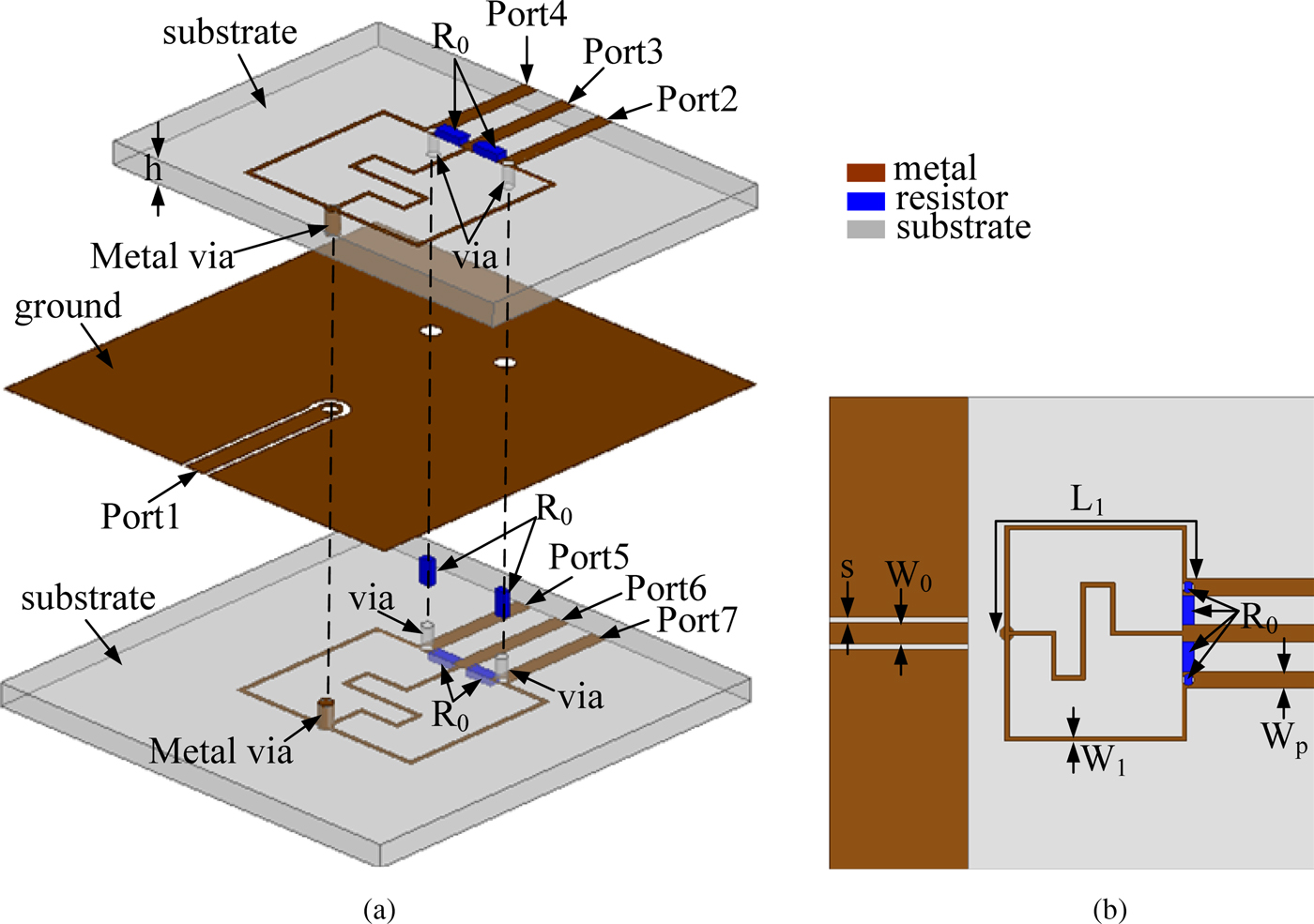
Fig. 1. The model of the novel four-way power-dividing structure. (a) Three-dimensional structure; (b) top view.
Meanwhile, the isolation network is circularly distributed and the isolation resistors R 0 are connected among neighboring TLs, as illustrated in Fig. 2. The isolation network constitutes a closed ring-shaped architecture; thus, the common node is avoided compared with the Wilkinson multi-way power dividers. Around the sided isolation resistor, the middle metal layer is etched to avoid the signal being shorted to the ground. Theoretically, the proposed structure could realize the power divider with arbitrary numbers of output ports.
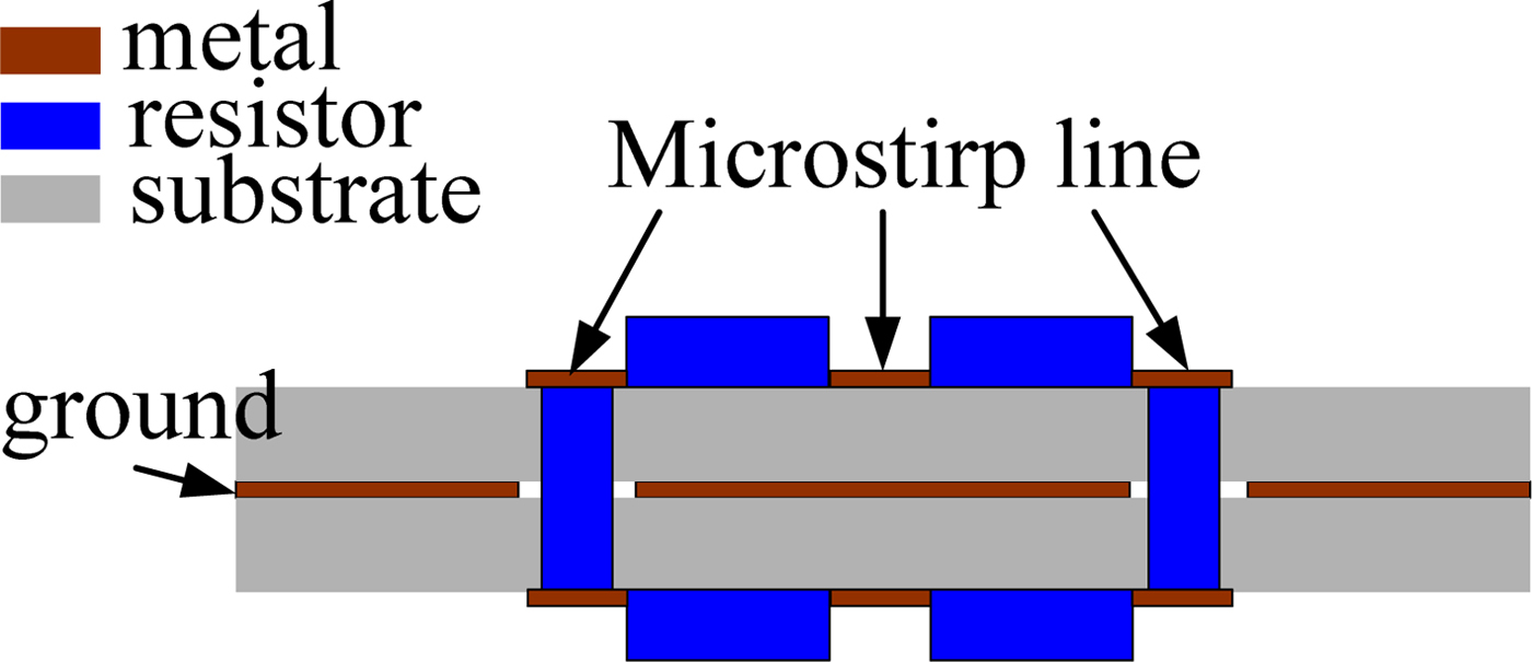
Fig. 2. Assembly layout of the isolation resistor.
Figure 3 gives the equivalent circuits of the direct 1–6-way power division networks. Z CPW and Z 1, Z 0 are the impedance of the input CPW TL and the microstrip TLs, respectively. Fig. 3(b) depicts the even-mode equivalent circuits.

Fig. 3. Equivalent circuits of the direct 1–6-way power divider. (a) Proposed architecture equivalent circuit; (b) even-mode equivalent circuit.
According to the even-mode equivalent circuit, the electric length of L 1 is chosen to be λ g /4 to realize the input impedance matching, where λ g is the guide wavelength at the operating center frequency. Thus, we have
 $$Z_1 = \sqrt 6 Z_0.$$
By developing the [S] matrix [Reference Saleh13] among the output ports, the isolation performance of the proposed power divider could be obtained. The isolation and output return loss could be given by
 $$S_{ij} = 2f_{ij}\left( {\sqrt {1 + 4\left( {{{Z_0} / {R_0}}} \right)}} \right) - {1 / n} - \delta _{ij},$$
where n is the number of the output ports, i = j = 2,3,…,7, δ ij is the Kronecker δ, and
 $$f_m\left( x \right) = x^{ - 1}\left( {y^{n/2 - m} + y^{m - n/2}} \right)\left( {y^{n/2} - y^{ - n/2}} \right)^{ - 1},$$
 $$\delta _{ij} = \left\{ {\matrix{ {\matrix{ {0,} & {i \ne j} \cr}} \cr {\matrix{ {1,} & {i = j} \cr}} \cr}} \right.,$$
with
 $y = (x + 1)/(x - 1),x = \sqrt {1 + 4(Z_0/R_0)},\quad m = \vert {i - j} \vert = 0,1,2, \ldots, 5$
.
$y = (x + 1)/(x - 1),x = \sqrt {1 + 4(Z_0/R_0)},\quad m = \vert {i - j} \vert = 0,1,2, \ldots, 5$
.
To obtain the optimal isolation and output impedance matching, the maximum of |S ij | should be minimized.
Therefore, through equations (1)–(4), the multi-way high-isolation power divider could be easily designed at the required frequency. The calculated results of equation (2) are shown in Fig. 4. It can be seen that the value of isolation and output return loss varies with the value of Z 0/R 0, and the minimized value of |S ij | is 0.13 (−17.7 dB) with Z 0/R 0 = 0.43 as labeled in Fig. 4.

Fig. 4. The calculated results of |S ij | against the value of Z 0/R 0.
According to the above analyses, the design procedure of the proposed power dividers is as follows:
-
(1) As the desired frequency f 0 is given, the guided wavelength of microstrip line λ g could be calculated based on the chosen substrate; therefore, L 1 can be derived. According to equation (1), the characteristic impedance Z 1 could be derived.
-
(2) According to equation (2), the value of the isolation resistor R 0 could be derived. Therefore, the multi-way power divider with optimal isolation and output impedance matching can be obtained.
III. EXPERIMENTAL RESULTS
Based on the analyses given above, a six-way high-isolation power divider/combiner was designed and fabricated. The structure was optimized in Ansys-HFSS. The used substrate is Taconic RF-35 with a dielectric constant ε r of 3.5, a thickness of 0.508 mm, and a loss tangent of 0.0018. The calculated and optimized dimensions are shown in Table 1.
Table 1. Circuit dimensions.

Figure 5 gives the fabricated six-way power divider. All the ports are terminated with the type-SMA connectors.
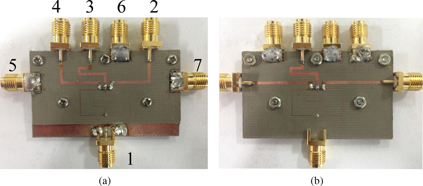
Fig. 5. Photograph of the fabricated power divider. (a) Top view; (b) bottom view.
The simulated and measured results of the six-way power divider are shown in Fig. 6. Figure 6(a) gives the simulated and measured results of the S-parameters. It shows that the measured and simulated results agree well with each other over the operating frequency band. The measured input return loss is larger than 15 dB from 1.82 to 2.38 GHz and larger than 20 dB from 1.97 to 2.22 GHz. The measured insertion losses are within 8.05 ± 0.15 dB including the insertion loss of SMA-connector to microstrip transitions over the frequency from 1.9 to 2.25 GHz. Figure 6(b) shows the measured result of isolation between the six output ports, and Fig. 6(c) shows the measured results of output return loss of each output ports. The measured isolations are all >15 dB over the frequency from 1.6 to 2.8 GHz, while the isolations in the operation center frequency are all >16.8 dB at 2.1 GHz. The measured output return losses are >16.2 dB from 1.0 to 2.7 GHz, which illustrates the calculated result in Fig. 4, and the measured result of each output port's phase is shown in Fig. 6(d). The final size of the power divider is 0.13 × 0.19 λ g .

Fig. 6. The measured and simulated results of the fabricated power divider. (a) Measured and simulated S-parameter; (b) measured and simulated isolation; (c) measured and simulated output return loss; (d) measured phase.
Table 2 shows the performance of some multi-way power dividers in recent years. It can be seen that this work realized better performances of isolation, output return loss, and insertion loss.
Table 2. Comparison with other multi-way power dividers.

RBW, relative bandwidth; ORL, output return loss; None, isolations <20 dB; NOP, number of output ports.
IV. CONCLUSION
This work presents a compact N-way power divider with good isolation and all ports impedance matching. It could be easily designed according to the equivalent circuits. The measured and simulated results agree well with each other; it indicates that the proposed power divider has the advantages of good isolation, compact size, excellent input and output impedance matching, and low insertion loss. The proposed structure could realize the power divider with arbitrary numbers of output ports.
ACKNOWLEDGEMENT
This work was supported by National Natural Science Foundation of China (Grant No 61271026).
 Shunyong Hu was born in Linyi, Shandong Province, China, in February 1987. He received the B.Sc. degree in Applied Physics from Shandong University of Science and Technology, Qingdao, Shandong, China, in 2010, and is currently working toward the Ph.D. degree in Electromagnetic Fields and Microwave Technology at UESTC (University of Electronic Science and Technology of China). His research interests include microwave and millimeter-wave power-combining technology and microwave passive component design.
 Kaijun Song (M'09-SM'12) received the M.S. degree in Radio Physics and the Ph.D. degree in Electromagnetic Field and Microwave Technology from the University of Electronic Science and Technology of China (UESTC), Chengdu, China, in 2005 and 2007, respectively. Since 2007, he has been with the EHF Key Laboratory of Science, School of Electronic Engineering, UESTC, where he is currently a full Professor. From 2007 to 2008, he was a Postdoctoral Research Fellow with the Montana Tech of the University of Montana, Butte, USA, working on microwave/millimeter-wave circuits and microwave remote-sensing technology. From 2008 to 2010, he was a Research Fellow with the State Key Laboratory of Millimetre Waves of China, Department of Electronic Engineering, City University of Hong Kong, on microwave/millimeter-wave power-combining technology and ultra-wideband (UWB) circuits. He was a Senior Visiting Scholar with the State Key Laboratory of Millimetre Waves of China, Department of Electronic Engineering, City University of Hong Kong in November 2012. He has published more than 90 internationally refereed journal papers. His current research fields include microwave and millimeter-wave/THz power-combining technology; UWB circuits and technologies; microwave/millimeter-wave devices, circuits, and systems; and microwave remote-sensing technologies. Professor Song is the Reviewer of ten international journals, including IEEE Transactions and IEEE Letters.
 Yong Fan (M'05) received the B.E. degree from Nanjing University of Science and Technology, Nanjing, Jiangsu, China, in 1985 and the M.S. degree from University of Electronic Science and Technology of China, Chengdu, Sichuan, China, in 1992. He is now with the School of Electronic Engineering, University of Electronic Science and Technology of China, where he is currently a full Professor. His current research interests include electromagnetic theory, millimeter-wave technology, communication, and system. He has authored and co-authored over 130 papers. Mr Fan is a senior member of the Chinese Institute of Electronics. He received the first award of science and technology of national industry, the second award of science and technology progress of ministry of electronic industry, the third award of science and technology progress of ministry of information industry, and the third award of science and technology progress of Sichuan province (twice).


