Introduction
In recent years, array antennas have attracted the attention of researchers due to their suitable performance in various possible communication applications. In this regard, paving the way to reach a highly reliable antenna system, many efforts have been devoted to design array antennas. Different applications such as beam switching [Reference Luna and Dussopt1], side lobe suppression [Reference Afoakwa and Jung2], solid angle scanning [Reference Xia, Muneer and Zhu3], and millimeter-wave application [Reference Semkin, Bisognin, Kyrö, Kolmonen, Luxey, Ferrero, Devillers and Räisänen4] are envisaged for array antenna structures. On the other hand, circularly polarized (CP) antennas exhibit better performance comparing with linearly polarized (LP) ones in terms of better mobility and penetration features [Reference Qu and Lim5, Reference Mener, Gillard and Roy6]. As known, CP is generated when two orthogonal electric field vectors are excited on the antenna body. A vast variety of techniques could be applied to generate the aforementioned orthogonal vectors. For instance, the authors in [Reference Zheng and Sun7] propose a high gain omnidirectional CP antenna for WLAN applications. Simple feed line is adopted to excite the antenna. To realize the CP, a helix-shaped slot is etched on outer conductor of the antenna. In [Reference Liu, Zhu and Choi8], a low-profile CP antenna is proposed with wide AR bandwidth. Two orthogonal pairs of parallel slots etched symmetrically onto a ground plane are utilized as the antenna ground plane, which yield CP achievement. Apart from simple antennas with CP feature, the combination of reconfiguration technology with simple antennas results in interesting observations. This is due to the fact that by embedding switches on the antenna body, more than one operating cases could be attained which extends the antenna functionality considerably. An example of such a configuration is proposed in [Reference Singh, Kanaujia, Dwari, Pandey and Kumar9] within which small isosceles right angle triangular sections are removed from diagonally opposite corners for the generation of CP with axial ratio bandwidth of 11.1%. Moreover, by switching PIN diodes across the slits ON and OFF, reconfigurable CP antenna is realized. Dual-band behavior with CP characteristics is exhibited by the proposed antenna. Based on the above discussion, to benefit the merits of both CP and array antennas, CP array antennas (CPAAs) have been regarded as a popular category of antennas exhibiting remarkable characteristics. Although many CPAAs have been proposed in the literature, there are still opportunities to enhance the performance of such antennas [Reference Rahman, Hossain, Azad Hossain, Nishiyama and Toyoda10–Reference Huang, Lin, Qiu, Jiang, Lei and Gua13]. For instance, utilizing simple array elements to be in line with techno-economic issues, proposing novel feeding strategies, and tuning the elements and their spacing such that the operating bands could be focused on applicable and mostly used frequency bands are some of the related topics.
Being stimulated by the aforementioned points, this paper aims at proposing novel 2 × 2 and 4 × 4 microstrip-fed slot array antennas with CP characteristics (CPSAAs). The single antennas utilized as the array elements are LP wide slot antennas (WSAs). These antennas are composed of a corner-truncated radiating patch on top and bottom edges with slotted ground plane. Moreover, three semi-circular-shaped slots are removed from the ground plane to further enhance the single-antenna performance. A simple rectangular feed line is also adopted to feed the antenna structure. By suitably arranging four and 16 samples of the aforementioned WSAs, 2 × 2 and 4 × 4 CPSAAs are obtained. It is worth mentioning that the proposed constituent single antennas are LP elements. This is while; by arranging the WSAs in an array structures, CP is generated. In fact, CP is achieved by proper combination of LP elements and finely tuning their spacing and dimensions. Analyzing the WSA and CPSAAs performance reveals that the proposed CPSAAs exhibit better performance including higher gain, wider bandwidth, and CP property with respect to WSAs. Specifically speaking, the proposed design offers the following advantages:
• Achieving CP feature through suitable arrangement and proper combination of LP elements.
• Utilizing simple structured elements with cost-effective and compact design.
• Adoption of a novel feeding mechanism which enhances both 10 dB impedance bandwidth and 3 dB AR bandwidth.
• Suitable performance in the form of both 2 × 2 and 4 × 4 designs.
This paper is organized in the following sections: section “Design of array element” studies the design process of WSAs as the array elements. Section “Feeding method” surveys the topology and performance of the proposed feeding network used for the array structures. In section “2 × 2 CPSAA design and performance”, the performance of the proposed 2 × 2 CPSAA is studied in detail. Besides, simulated and measured results are studied and compared in depth. A comparison of the proposed 2 × 2 CPSAA configuration with some previous designs is carried out in section “Comparison”. Structural analysis and performance of 4 × 4 CPSAA is presented in section “4 × 4 CPSAA design and performance”. Ultimately, section “Conclusion” concludes the paper.
Design of array element
This section establishes the design process of the single-antenna element, which is utilized as the array element. The configuration of the proposed antenna is shown in Fig. 1. It is seen that the antenna is composed of a simple feed line with a corner-truncated radiating patch on top side of the substrate. On backside, a simple ground plane with a wide rectangular slot is embedded. Three semi-circular-shaped slots are removed from the lower edge of the ground plane slot to further enhance the antenna performance. FR4 substrate with a total size of 20 mm × 18 mm and thickness of 1 mm is adopted as substrate. All antenna parameter values are reported in Fig. 1. To shed light on design process and performance enhancement process of the WSA, final antenna geometry achievement is discussed in a four-step process shown in Fig. 2. First, a simple rectangular feed line with a rectangular patch on top side and a slotted ground plane on backside is adopted (Ant. 1). In the sequel, three semi-circular slots are removed from the ground plane structure (Ant. 2). Then, two triangular-shaped slots are removed from the lower edge of the radiating patch (Ant. 3). Finally, top edge of the radiating patch is also truncated to achieve the final configuration (Ant. 4). The aforementioned antenna structures are simulated using Ansoft High Frequency Structure Simulator (HFSS) and the corresponding S 11 curves are plotted in Fig. 3. As the results clearly indicate, the operating frequency bands of Ant. 1 are in 3–5.3 and 8.6–10.1 GHz. Regarding Ant. 2, it is seen that by removing the semi-circular slots, the frequency band of 3.1–4.1 and 7.8–10.7 GHz is covered. The bandwidth is extended to higher frequencies. In the sequel, in Ant. 3, the truncation of the lower edge of the ground plane yields the impedance-matching improvement over the entire frequency band. This modification results in the coverage of 3.5–4.3 and 5.1–10.4 GHz. Finally, Ant. 4 operates over the frequency band of 3.1–10.6 GHz, which is exactly in line with UWB frequency band. As well, impedance matching is enhanced at 4–6 GHz.
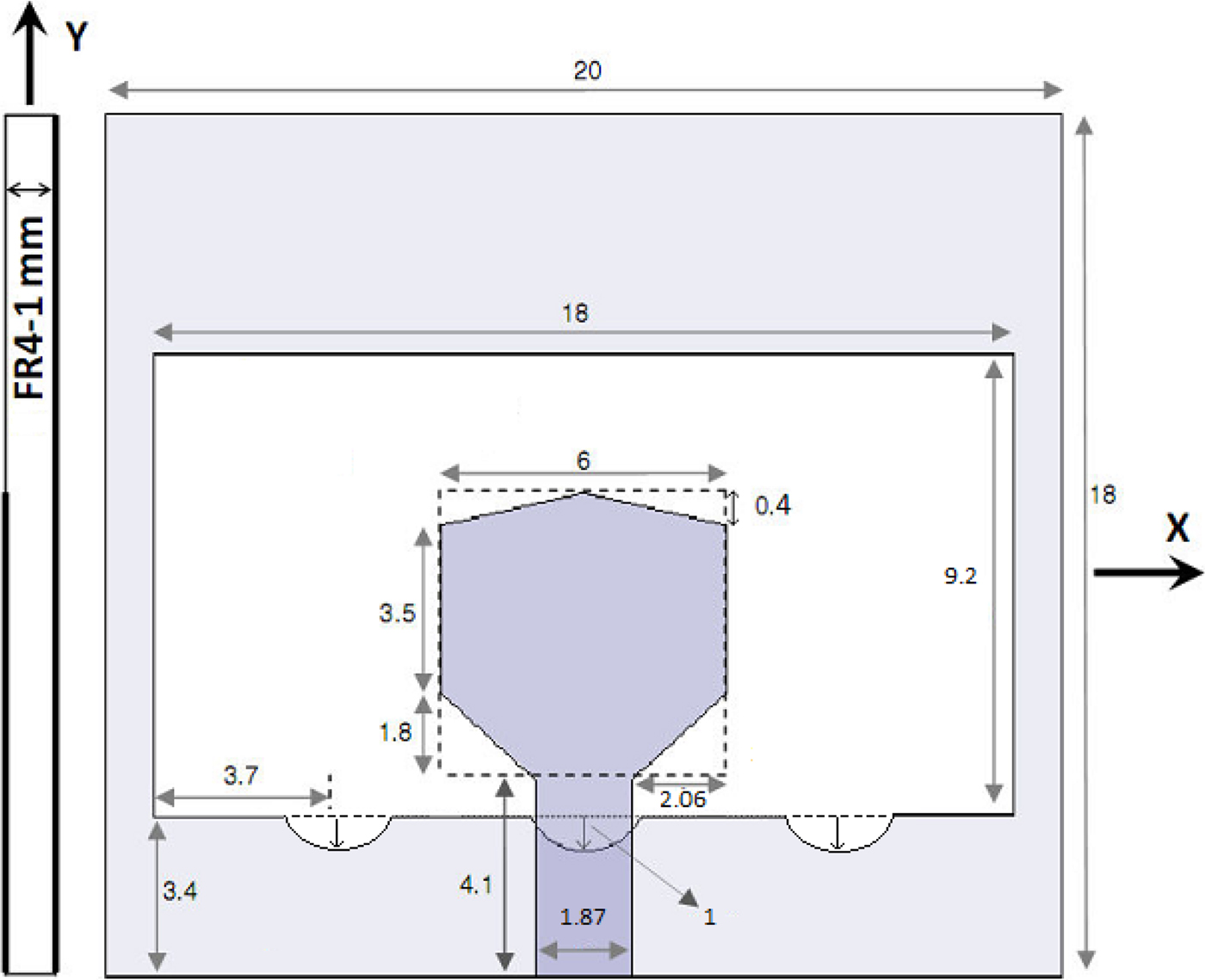
Fig. 1. Single WSA configuration and parameters.
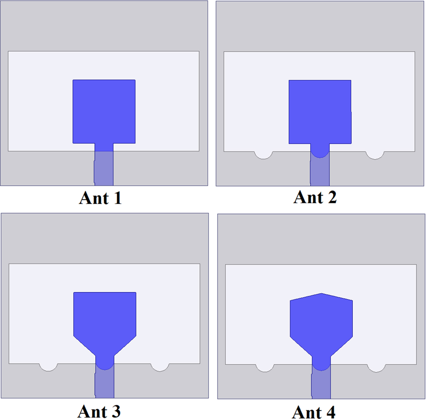
Fig. 2. Design steps of the single WSA.

Fig. 3. S 11 curves for the four design steps of single WSA.
It is worth noting that the embedment of slots does not excite new modes, but modifies the higher order orthogonal resonance frequency in microstrip antennas. The resonance frequency is a function of slots dimensions and location, as follows [Reference Deshmukh and Ray14]:
 $$f\, = \,\displaystyle{c \over {2{\rm \;} L_e\sqrt {\varepsilon _{re}}}}, $$
where L e is the electric length of the slot and ε re relates to the antenna material. WSA gain is plotted in Fig. 4. It is seen that gain values increase up to 6 dB over the operating frequency band. As well, based on the obtained results in Fig. 5, an efficiency between 60 and 80% is observed over the operating frequency band. Moreover, radiation pattern at the resonance frequency of 9.5 GHz is illustrated in Fig. 6. As can be seen, the obtained radiation patterns are in line with communication systems requirements.

Fig. 4. Simulated gain of the proposed WSA.
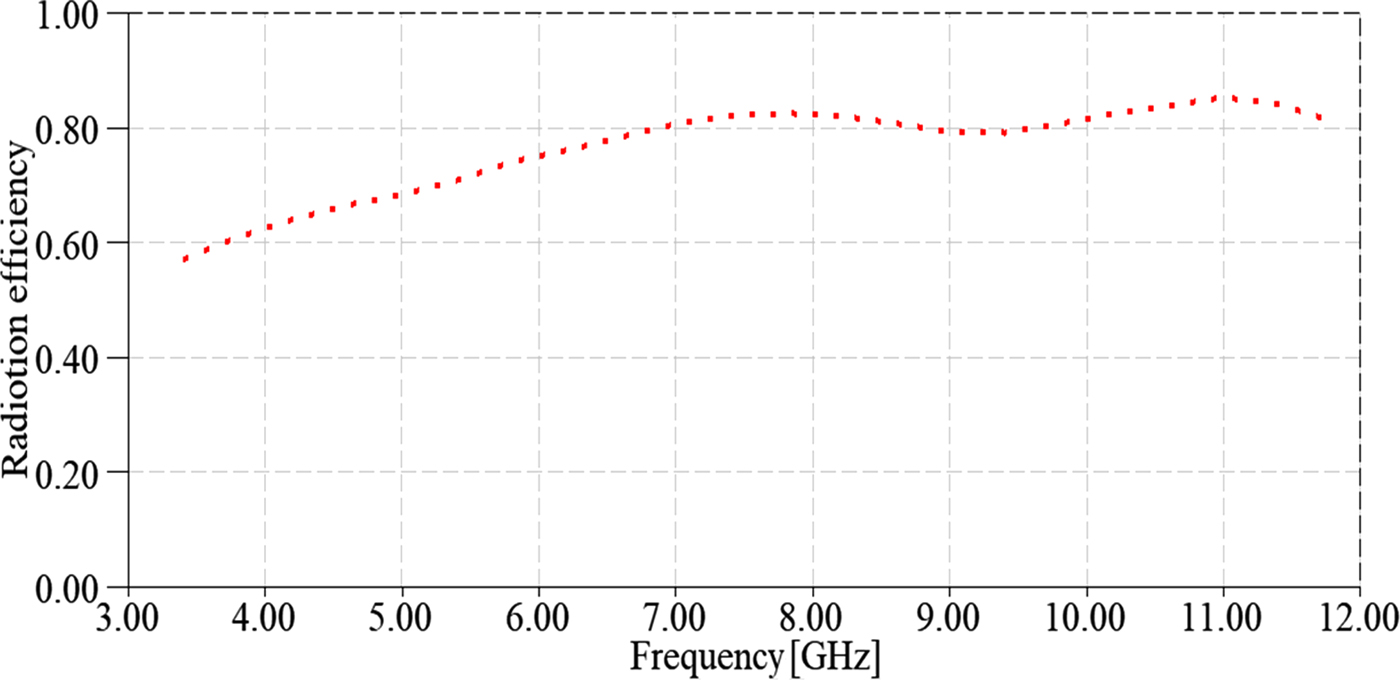
Fig. 5. Simulated radiation efficiency of the proposed WSA.

Fig. 6. Radiation pattern of WSA at 9.5 GHz.
To shed light on the advantages of the proposed single antenna with respect to some of the previously designed antennas, Table 1 compares the structural and performance of the presented WSA and some other antennas. The comparison is based on the antenna total size, 10 dB impedance bandwidth, and peak gain values. As can be seen, the single WSA is the smallest one among the antennas. This is while the candidate antennas performance comparison reveals that the proposed design is ranked between the antennas with widest bandwidth. Although having smaller size which yields less freedom degree, the proposed WSA provides a high and suitable gain value.
Table 1. Comparison of the proposed WSA with some previously designed antennas

Feeding method
Arranging the aforementioned WSAs in array configuration calls the need for an efficient feeding system, which could suitably meet the requirements of the array antenna. In single antennas, usually a simple feed network provides the needed features of the antenna system, but this issue is not a simple matter in array antenna structures. As an array antenna consists of hundreds of thousands of single antennas, feeding strategy selection becomes a more important factor, which needs careful and meticulous considerations. Designing feed networks has been the main focus of many studies presented so far. One of the most interesting and capable ones is the sequential phase (SP) feed network. Different forms of SP feed and corresponding results have been surveyed, which although end in applicable and interesting results, still are faced with some challenges. Accordingly, more trustworthy solutions are required. It has been shown that adoption of SP feed in 2 × 2 CPAAs enhances the array functionality to a great extent. Detailed discussion on design of SP feed could be accessed in [Reference Evans, Gale, Aljibouri, Lim, Korolkwiwicz and Sambell22]. With the aim of benefitting the advantages of SP feed network, a modified SP feed is deployed in the present design shown in Fig. 7. As can be seen, a sector of 270° with different radii in each comprising part and four strips are the constituting elements of the proposed SP feed network. Due to the inherent features of this feed mechanism, different phases with stable difference are excited at the end of each strip, which yields CP generation. As mentioned earlier, SP feed network facilitates polarization purity increment, impedance matching, and pattern symmetry in CPAAs.

Fig. 7. SP feed network configuration of the proposed 2 × 2 CPSAA.
To scrutinize the advantages of the proposed feeding technique over the simple SP feed network, two antennas with simple and proposed feeding configurations are studied. The simple SP feeding method consists of a sector of 270° with the same widths in constituent sections, named as Ant. 1 in Fig. 8. As can be seen, Ant. 2 is the antenna with the proposed feed network in this paper. The simulation results are shown in Figs 9 and 10 for S 11 and AR bandwidths, respectively. The results clearly indicate that both S 11 and AR bandwidth are enhanced significantly by the application of proposed feeding mechanism, that is, the utilization of different widths in different sections of the sector of 270°. It is seen that the adoption uniform widths yield no CP, this is while; by modifying the widths of the sections, wide CP is obtained in 4.5–8 GHz frequency band.
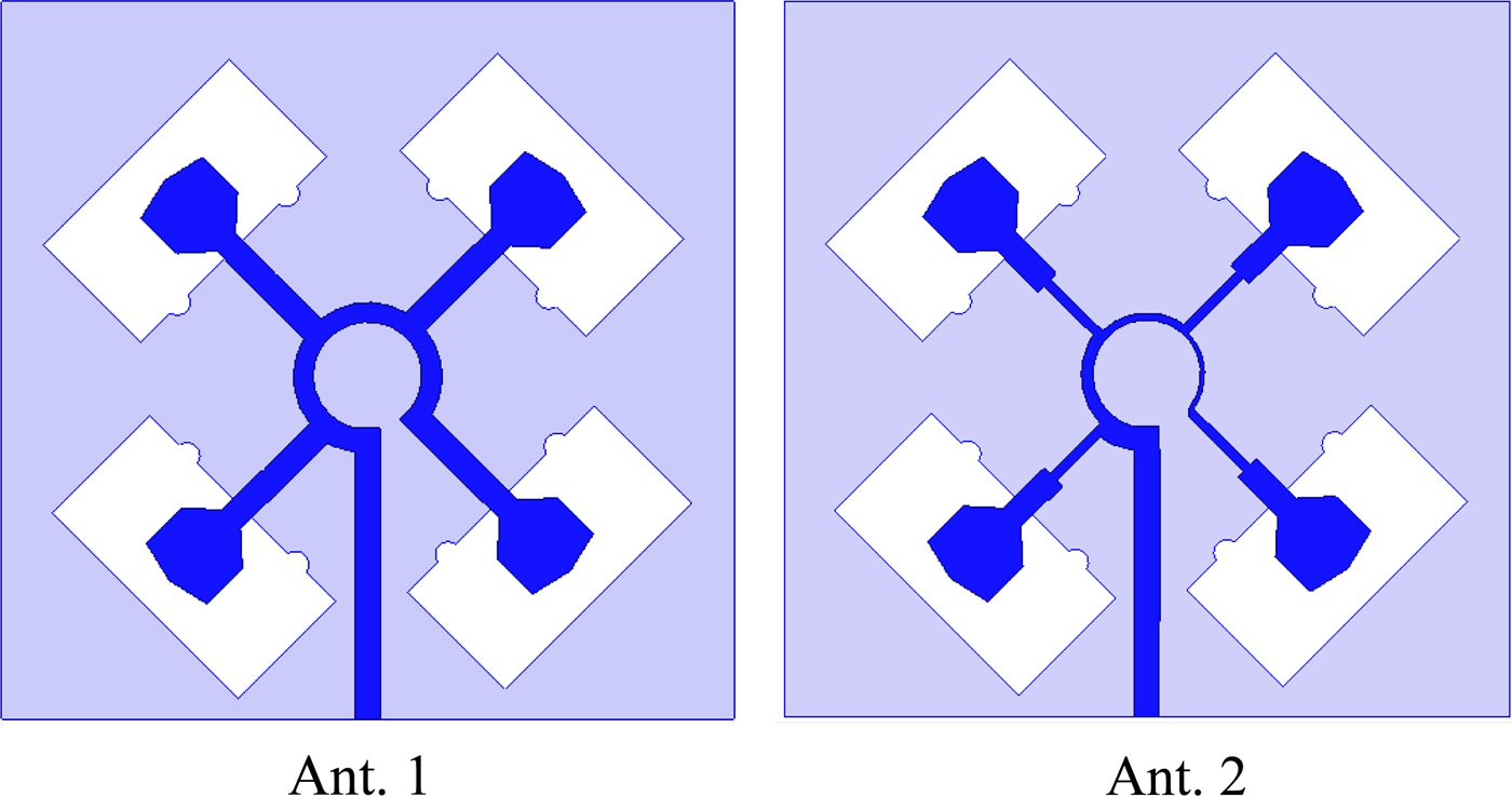
Fig. 8. Two configurations of feed networks.
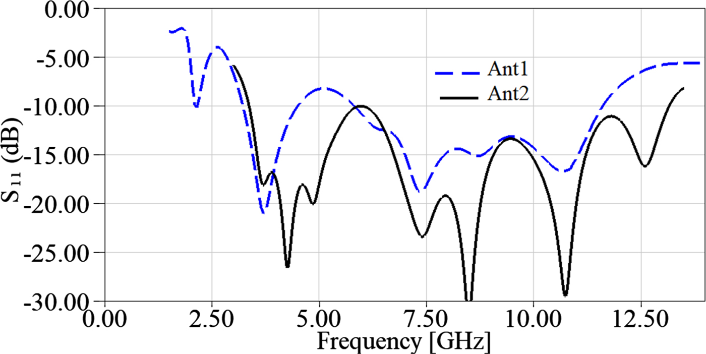
Fig. 9. S 11 curves for Ant. 1 and Ant. 2 with different feeding configurations.
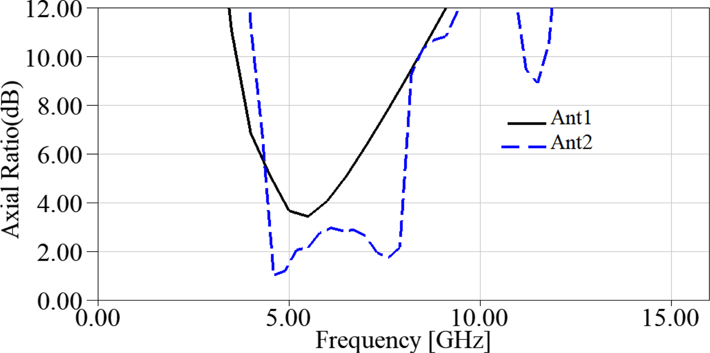
Fig. 10. AR curves for Ant. 1 and Ant. 2 with different feeding configurations.
2 × 2 CPSAA design and performance
Design process and performance of the WSA was discussed in the previous section. To further enhance the antenna performance, the proposed element is arranged in the form of a 2 × 2 CPSAA excited with the aforementioned SP feed network. As clearly shown in Fig. 11, four WSAs are connected to the four strips originated form the SP feed line. On top side of the substrate, the SP feed network and four corner-truncated patches are printed. Besides, on backside, four wide slots are included. The overall size of the 2 × 2 CPSAA is 50 mm × 50 mm × 1 mm which is more compact with respect to many of the previous designs. Moreover, detailed values of the proposed SP feed are reported in Table 2.
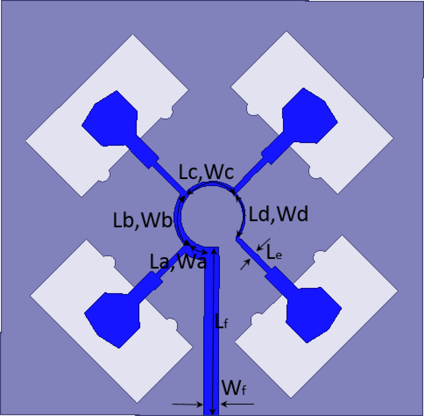
Fig. 11. SP feed network configuration of the proposed 2 × 2 CPSAA.
Table 2. SP feed network parameters values (all parameters are in mm)

To analyze the proposed 2 × 2 CPSAA performance in real applications, an experimental prototype is fabricated and measured. Top and bottom views of the fabricated antenna are shown in Fig. 12. As it was mentioned in WSA design, FR4 material with a thickness of 1 mm is adopted as the substrate. Moreover, the fabricated prototype under measurement process is shown in Fig. 13. Simulated and measured S 11 curves for the proposed 2 × 2 CPSAA are illustrated in Fig. 14. Close investigation of S 11 curve performance reveals considerable enhancement with respect to the WSA. As it was shown in Fig. 3, the single WSA operates over the frequency band of 3.1–10.6 GHz. This is while; the 2 × 2 CPSAA covers the frequency band of 3–13.1 GHz. Moreover, agreement of the simulated and measured results confirms the CPSAA suitable performance. As an important point, it should be noticed that the single array elements, namely WSA, are LP elements, but when arranged in the form of 2 × 2 SAA, exhibit CP characteristics. Simulated and measured AR and gain values shown in Fig. 15 are highly compatible with each other, which confirm the outperformance of the proposed design. As clearly seen, CP is obtained in 4.5–8 GHz within which gain values vary between 6 and 8 dBic. Simulated radiation efficiency of the proposed array antenna is plotted in Fig. 16. As can be seen, the efficiency varies between 80 and 90% over the obtained frequency band of 4.5–8 GHz where CP is observed. Moreover, right-hand circular polarization (RHCP) and left hand circular polarization (LHCP) radiation patterns at 4.2 and 8.3 GHz are plotted in Fig. 17. Moreover, about 20 dB difference is observed between the Co and cross polarization values.
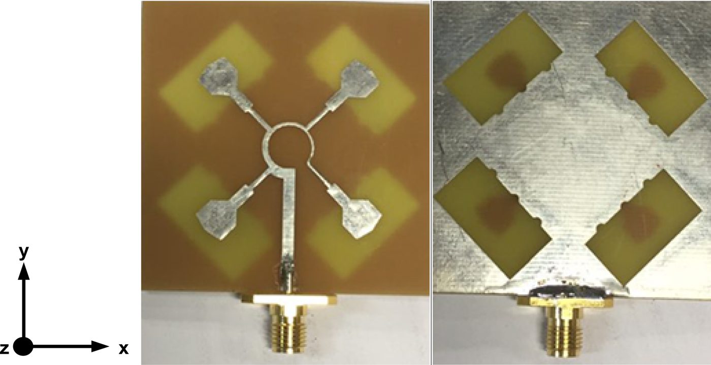
Fig. 12. Top and bottom views of the fabricated prototype.
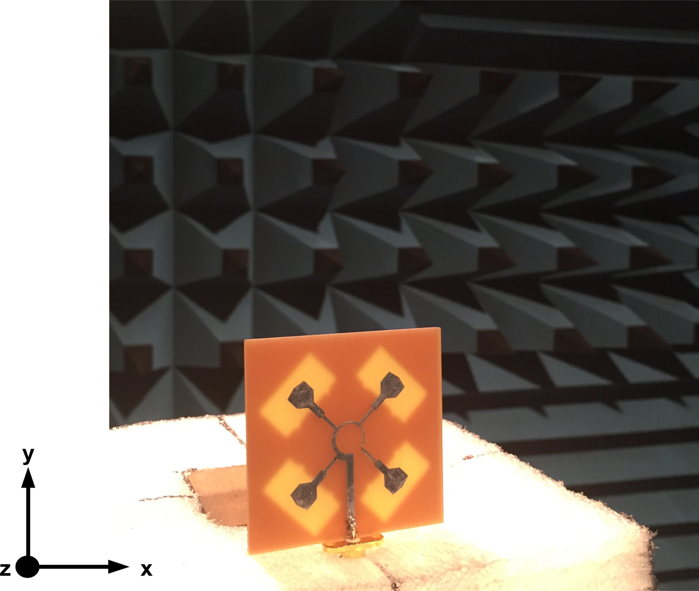
Fig. 13. The fabricated prototype of 2 × 2 CPSAA in measurement process.

Fig. 14. Simulated and measured S 11 curves for the proposed CPSAA.
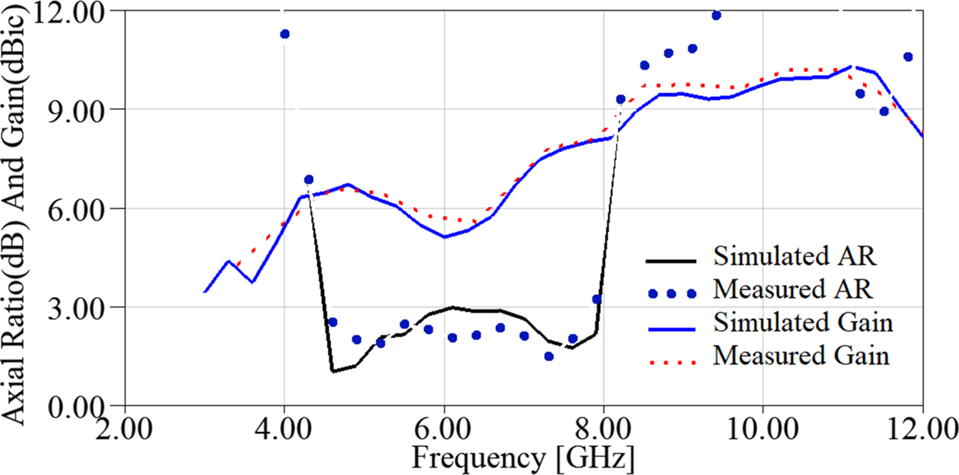
Fig. 15. Simulated and measured AR and gain curves for the proposed CPSAA.

Fig. 16. Simulated radiation efficiency for the proposed CPSAA.
Fig. 17. Simulated and measured RHCP and LHCP radiation patterns of the proposed 2 × 2 CPSAA, (a) 4.2 GHz and (b) 8.3 GHz.
With the aim of more discussion on the proposed 2 × 2 CPSAA antenna performance, surface current distribution at the frequency of 4.5 is shown in Fig. 18. The results are depicted at 0, 90, 180, and 270° phases. The direction of the dominant current at each phase is shown by red arrows. Following the direction of currents confirms RHCP at +z direction and LHCP at –z direction.
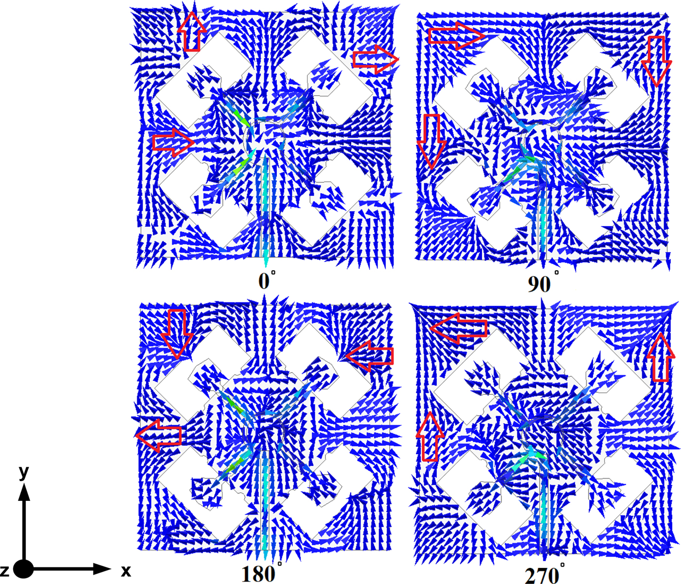
Fig. 18. Surface current distribution on the antenna at 4.5 GHz.
Comparison
Comparison of the proposed performance of the 2 × 2 array structure with some of the previous designs would be fruitful to shed light on the advantages of the present work. To this end, Table 3 provides the characteristics of some previously published designs in [Reference Sedgeechongaralooye-yekan, Naser-Moghaddasi and Sadeghzadeh23–Reference Maddio28] and the proposed antenna. As the provided data imply, the proposed antenna is the smallest among the antennas in [Reference Sedgeechongaralooye-yekan, Naser-Moghaddasi and Sadeghzadeh23–Reference Yang, Zhou, Yu and Li27]. As can be seen, the antenna in [Reference Maddio28] is smaller. This is while; the widest 10 dB impedance bandwidth and 3 dB AR bandwidth are obtained by the present work. Regarding the peak gain values, it is seen that the proposed design in this work offers an acceptable and high gain. As well, bidirectional radiation pattern is observed for the antenna. It is clearly seen that compact size, and wide impedance and AR operating bandwidths are of the evident merits exhibited by the array antenna in this paper.
Table 3. Summary of the characteristics of some previously designed structures and the present work

4 × 4 CPSAA design and performance
Further performance enhancement could be realized by increasing the number of single WSAs in a 4 × 4 array. Sixteen single WSAs are suitably arranged in the form of an array antenna with enhanced performance with respect to both WSA and 2 × 2 CPSAA. Figure 19 illustrates the geometry of the proposed 4 × 4 CPSAA. As seen, SP feed network, as discussed in previous sections, is adopted as the feeding strategy. The fabricated prototype of the 4 × 4 array and the antenna under measurement are illustrated in Figs 20 and 21, respectively.
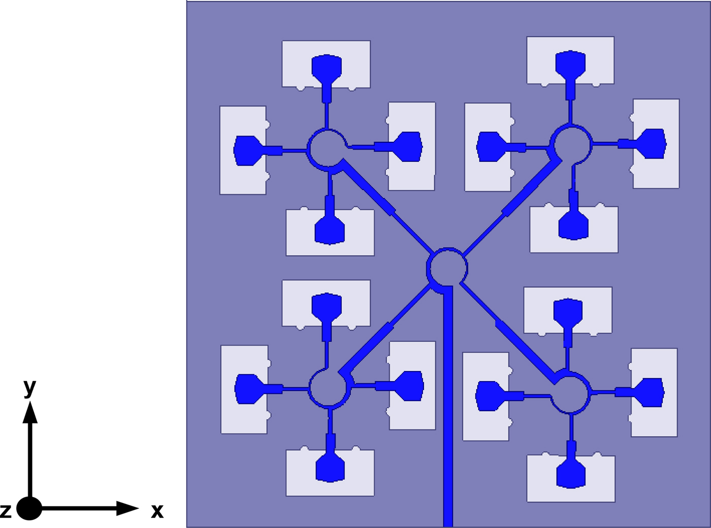
Fig. 19. Geometry of the proposed 4 × 4 CPSAA.
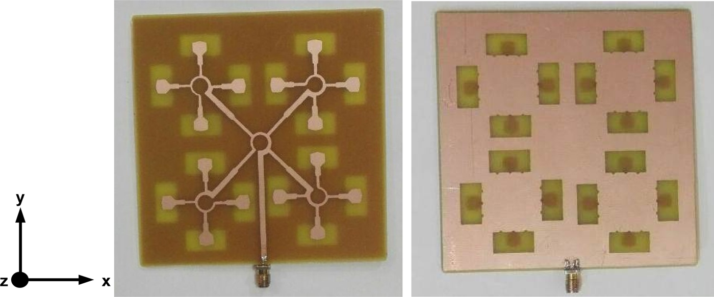
Fig. 20. Top and bottom view of the fabricated prototype of the 4 × 4 CPSAA.
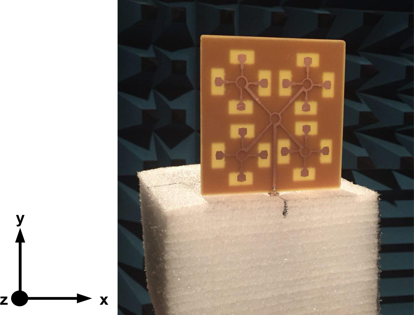
Fig. 21. 4 × 4 CPSAA under measurement process.
Simulated and measured S 11 curves for this array structure are shown in Fig. 22. It is seen that the performance is remarkably enhanced specially at lower frequencies. The agreement of the simulated and measured results confirms that the frequency band of 1.4–12.3 GHz is covered by the array. As well, simulated and measured AR curves are compared in Fig. 23. The results reveal CP generation at 4.6–8.8 GHz, which is better than the results obtained for 2 × 2 CPSAA. Moreover, simulated and measured gain results are depicted in Fig. 24. A maximum gain of 11 dB is observed for the proposed array over the operating frequency band.

Fig. 22. Simulated and measured S 11 curve for the proposed 4 × 4 CPSAA.
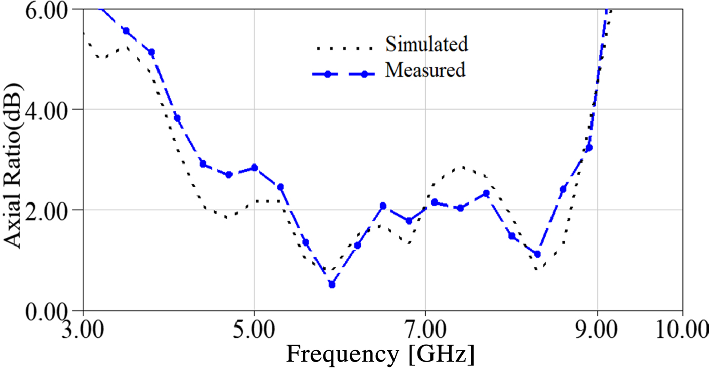
Fig. 23. Simulated and measured AR curve for the proposed 4 × 4 CPSAA.

Fig. 24. Simulated and measured gain curve for the proposed 4 × 4 CPSAA.
Radiation pattern of the proposed 4 × 4 CPSAA is depicted in Fig. 25 at 5 and 7.5 GHz for ɸ = 0 and 90°. It is observed that a suitable radiation pattern for communication systems is achieved, which confirms the antenna outperformance in relevant applications.

Fig. 25. Simulated and measured radiation patterns of the proposed 4 × 4 CPSAA, (a) 5 GHz, (b) 7.5 GHz.
To have a more precise record on performance improvements, the operational characteristics of the proposed single WSA, 2 × 2 CPSAA, and 4 × 4 CPSAA are summarized in Table 4. Based on the data provided in Table 4, both 10 dB impedance bandwidth and 3 dB AR bandwidth are improved by increasing the number of used WSAs in array structures.
Table 4. Structural and performance characteristics of the proposed arrays and array element

Conclusion
A simple design of simple single slot antenna with LP feature over the frequency band of 3.1–10.6 GHz was designed and discussed in this paper. The WSA configuration was composed of a simple radiation patch with truncation on the four corners. Besides, a slotted ground plane was included. Then, with the aim of performance enhancement, the aforementioned WSA was arranged in the form of 2 × 2 and 4 × 4 CPSAAs. A novel design of SP feed network, which is composed of a sector of 270° with unequal widths in three sections along with four strips, feeds the array structure. The proposed CPSAAs operate over the frequency bands of 3–13.1 GHz with CP at 4.5–8 GHz and 1.4–12.3 GHz with CP at 4.6–8.8 GHz, respectively, based on 2 × 2 and 4 × 4 ones. Wide impedance and AR bandwidth, higher gain values, and good radiation properties are some of the merits of the proposed CPSAAs.
 Alireza Haghshenas was born in 1966 in Iran. He received his B.Sc and M.Sc in communication engineering in 1994 and 2009 respectively. Now, he is a Ph.D candidate in Communication engineering in Urmia University, Urmia, Iran. His research interests include array antennas and circular polarization realization techniques.
 Changiz Ghobadi was born in June, 1960 in Iran. He received his B.Sc. in Electrical Engineering Electronics and M.Sc. degrees in Electrical Engineering Telecommunication from Isfahan University of Technology, Isfahan, Iran and Ph.D. degree in Electrical-Telecommunication from University of Bath, Bath, UK in 1998. From 1998 he was an Assistant Professor and now he is a Professor in the Department of Electrical Engineering of Urmia University, Urmia, Iran. His primary research interests are in antenna design, radar and adaptive filters.
 Javad Nourinia received his B.Sc. in Electrical and Electronic Engineering from Shiraz University and M.Sc. degree in Electrical and Telecommunication Engineering from Iran University of Science and Technology, and Ph.D. degree in Electrical and Telecommunication from University of Science and Technology, Tehran Iran in 2000. From 2000 he was an Assistant Professor and now he is a Professor in the Department of Electrical Engineering of Urmia University, Urmia, Iran. His primary research interests are in antenna design, numerical methods in electromagnetic, microwave circuits.
 Maryam Majidzadeh was born in 1987 in Urmia, Iran. She received her B.Sc. degree in electrical engineering from Urmia university in 2009. As well, she received her M.Sc. and Ph.D. degrees in communication engineering from the same university in 2012, and 2016 respectively. She is now assistant professor in Department of Electrical and Computer Engineering, Urmia Girls Faculty, West Azarbaijan branch, Technical and Vocational University (TVU), Urmia, Iran. Her research interests include antenna design, antenna miniaturization techniques, circularly polarized antennas, array antennas, frequency selective surfaces and electromagnetic compatibility.
 Saeed Mohammadi-Asl was born in Urmia, Iran 1984. He received his B.Sc. and M.Sc. degrees in Electrical (Telecommunication) engineering from Urmia University, Urmia, Iran in 2008 and 2010, respectively. His primary research interests are in antenna design, numerical methods in electromagnetic and microwave components.