I. INTRODUCTION
Recently, developing ultra-wideband (UWB) components, such as antennas and filters, has become a topic of increasing interest among researchers worldwide. This is due to the fact that UWB technology is of strong demand in low-power, high-rate wireless applications [Reference Schantz1]. Maximum permitted power levels approved by the Federal Communication Commission (FCC) for UWB transmission is only 0.5 mW over the entire 7.5 GHz bandwidth (power spectral density (PSD)= −41.3 dBm/MHz) [2]. For wireless communications in particular, this low value of PSD allows UWB technology to overlay already available services such as the WiMAX and the IEEE 802.11 WLANs that lie within the UWB frequency range. In addition, low probability of intercept capability of UWB signals can be used to covert communications and for the detection of buried mines in the ground penetrating radar applications [Reference Allen, Dohler, Okon, Malik, Brown and Edwards3]. More recently, UWB technology is utilized in microwave and biomedical imaging [Reference Allen, Dohler, Okon, Malik, Brown and Edwards3–Reference Savelyev and Yarovoy5]. Applications of this type such as early detection of breast cancer are among the research topics of growing interest [Reference Li, Bond, Van Veen and Hagness6].
Compact planar UWB antennas with different shapes and types have been reported in the literature [Reference Abbosh and Bialkowski7–Reference Chen, See and Qing11]. In [Reference Abbosh and Bialkowski7], planar UWB antennas of circular and elliptical shapes have been presented. An LI-shaped coplanar waveguide (CPW)-fed monopole antenna has been proposed in [Reference Joon and Yong8]. This UWB antenna has a compact design with a 30 × 25 mm2 area on a substrate of dielectric constant 3.8. In [Reference Zhu9], a linearly tapered slot UWB antenna was made compact by etching the tapered slot from one side while introducing a periodic pattern of cuts on the other side. The achieved area size was 36 × 35 mm2 which is a 51% reduction in size from the standard linear tapered slot antennas. A CPW-fed UWB antenna with a rectangle shape radiator has been proposed in [Reference Lee, Sun and Huang10]. The matching realized in the UWB band has been achieved by notching the two ground planes symmetrically. This structure has an area of size 39 × 33.6 mm2. In [Reference Chen, See and Qing11], a standard printed antenna with a rectangular radiator and a finite-size ground plane has been modified to reduce ground plane effects and to achieve compactness. A notch has been cut from the radiator and a small strip has been attached to the notched side of the radiator. This has led to a significant decrease in the overall size of the antenna to 25 × 25 × 1.5 mm3. Compact planar UWB antennas with single-and dual-notched bands have also been presented in the literature. In [Reference Shagar and Wahidabanu12], a 5.15–5.9 GHz band notched UWB slot antenna has been proposed. A CPW-fed UWB antenna showing dual band-notched performance has been developed in [Reference Malik, Kalaria and Kartikeyan13]. The two rejected bands were at 3.5 and 5–6 GHz. This antenna had a compact size of 30 × 20 × 1.524 mm3.
In this paper, a compact finite-ground coplanar waveguide (FGCPW)-fed flag-shaped UWB monopole antenna is presented. The antenna is developed from an FGCPW-fed strip monopole by asymmetrically loading it with a rectangle strip. The significant increase in bandwidth of the proposed antenna when compared with the basic strip monopole is attributable to the introduced loading. To analyze the effect of each parameter on the antenna's performance, parametric studies are conducted. Also, design equations of the proposed antenna are provided so that the antenna can be easily reproduced using different substrates. Standard antenna parameters such as the reflection coefficient, radiation patterns, and gain are measured. To throw light on the suitability for pulse communications, the time domain characteristics of the FGCPW-fed UWB antenna are investigated. Mainly, the distortion introduced by the antenna is investigated qualitatively, by comparing input and received signals, and quantitatively, by computing the fidelity factor (FF). Finally, the effective isotropic radiated power (EIPR) emission level of the proposed antenna is computed and tested against FCC emission masks. The organization of the paper is as follows: Section II describes the geometry of the proposed antenna and its development from the basic strip monopole. The parametric studies and design equations are presented in Sections III and IV, respectively. In Section. V, the experimental results are reported and the transient analysis are discussed in Section VI. The paper is concluded in Section VII.
II. ANTENNA GEOMETRY AND SIMULATION
A) Geometry development from the basic strip monopole
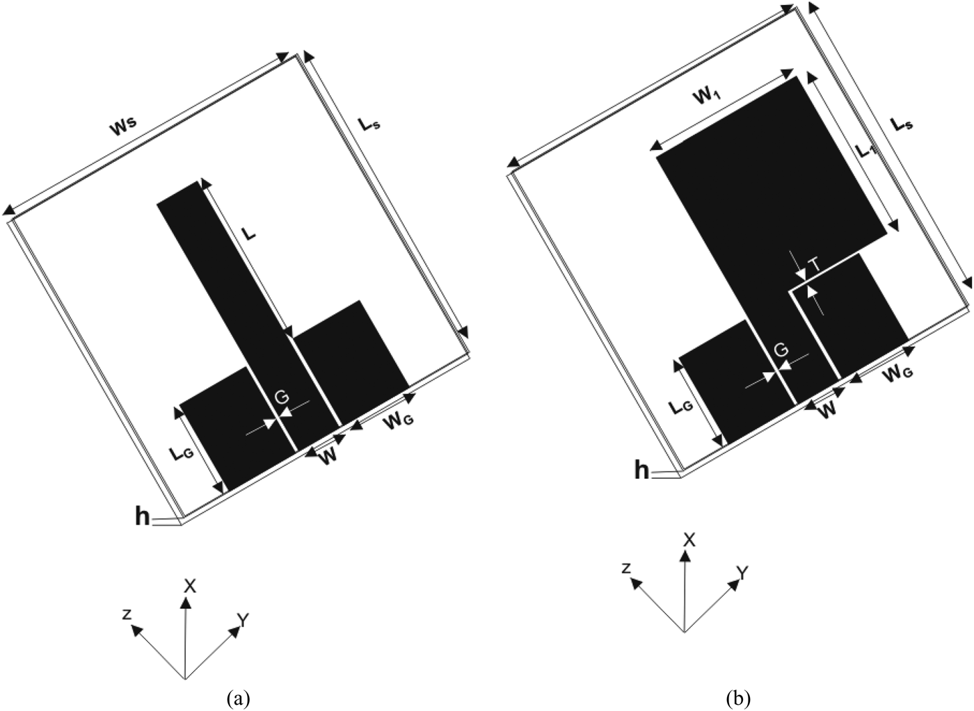
Figure. 1(a), shows the geometry of the basic FGCPW-fed strip monopole antenna, which will be developed into an UWB radiator. By optimizing the parameters of this monopole, various modes can be simultaneously excited and multi-mode operation can be achieved. This fact can be utilized to develop the strip monopole into an UWB antenna. To realize the UWB operation, the strip monopole should be loaded in a manner that lowers the resonant frequencies of the operational mode while increasing their matching bandwidth. In this paper, the proposed approach is to load the basic strip monopole asymmetrically with a rectangular strip making it flag-shaped as shown in Fig. 1(b). To verify the proposed approach, the basic strip monopole and the proposed UWB antenna are both simulated using Agilent's Advanced Design system (ADS) software. The substrate of both the antennas has a relative dielectric constant ε r = 4.4, thickness h = 0.6 mm, length L s = 30 mm, and width W s = 30 mm. In order to have a 50 Ω input impedance, the gap G and the strip width W for both the antennas are calculated as instructed in [Reference Ghione and Naldi14] and are found to be G = 0.35 mm and W = 3 mm, respectively. A ground plane of length L G = 10 mm and width W G = 7 mm is found to provide good matching performance. The basic strip monopole is designed to have a strip length L = 18 mm, which corresponds to the first resonance at 3.25 GHz. For the proposed UWB antenna, total strip width W 1 and the distance T between the loading strip and the ground plane are optimized to achieve the UWB performance. However, the total length L 1 + T is kept equal to the strip length of the basic monopole. The optimized parameters of the proposed UWB antenna were found to be: W 1 = 14.5 mm, T = 0.2 mm, and L 1 = 17.8 mm.

Fig. 1. Geometry of the FGCPW-fed antennas: (a) the basic strip monopole antenna; (b) the proposed UWB antenna.
B) Simulation results
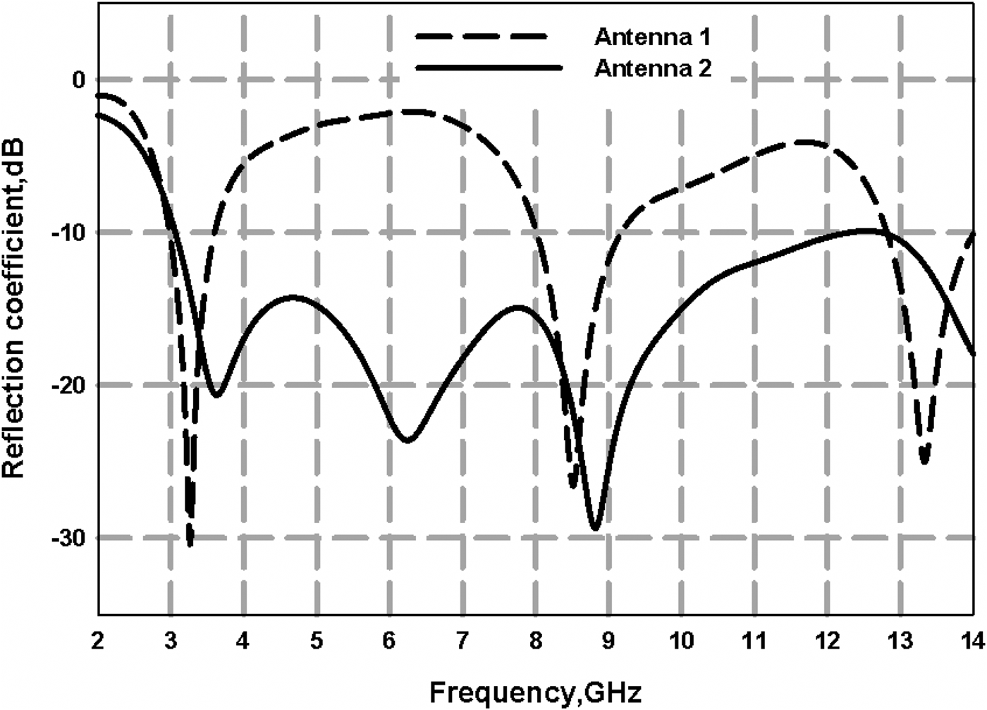
The simulated reflection coefficients of both antennas are shown in Fig. 2. The multi-band behavior of the basic strip monopole can be observed from Fig. 2 as three resonances centered at 3.25, 8.5, and 13.3 GHz are properly excited. From the reflection coefficient of the proposed antenna in Fig. 2, it can be seen that the proposed loading has lowered the frequencies of the higher two resonances and slightly has increased the first resonant frequency. Also, it has increased the matching bandwidth, and as a result, has achieved the required UWB performance. The current distributions at the three resonances of the flag-shaped UWB antenna are shown in Fig. 3.

Fig. 2. Simulated reflection coefficients of the FGCPW-fed antennas: (a) the basic strip monopole antenna (antenna 1); (b) the proposed UWB antenna (antenna 2).

Fig. 3. Simulated current distributions of the proposed UWB antenna at its three resonances.
III. EFFECT OF DESIGN PARAMETERS
In this section, a number of simulated parametric studies are conducted to understand the effect of each design parameter on the proposed antenna's performance as indicated by the reflection coefficient. In each study, only one parameter is varied while the rest are kept unchanged. Also, the value of the varied parameter that offers the best impedance matching will be considered as optimal and will be used in section IV to develop design equations. For the first study, the dimensions are the same as those presented in the previous section.
A) Effect of the loading strip length L1
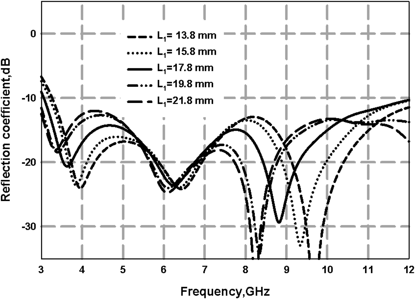
In the first study, the effect of the loading strip length L 1 is investigated. It is varied from 13.8to 21.8 mm in steps of 2 mm. Figure 4 shows the effect of varying the strip length on the reflection coefficient. It can be inferred from Fig. 4 that the increase of L 1 lowers the frequency of the three resonances. To comply with the FCC regulations, the reflection coefficient of an UWB antenna must be less than −10 dB in the range between 3.1 and 10.6 GHz. However, this is not the case for L 1 values of 13.8 and 15.8 mm as the reflection coefficient value is above −10 dB at 3.1 GHz for both cases. Although UWB performance is obtained for L 1 values between 17.8 and 21.8 mm, the value L 1 = 17.8 mm is selected for compactness.

Fig. 4. Effect of rectangular strip length L 1 on the reflection coefficient of the proposed FGCPW-fed UWB antenna.
B) Effect of the total strip width W1
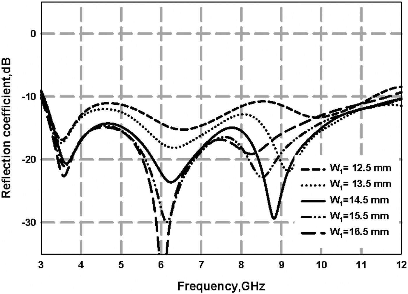
In the second parametric study, the width of the total strip W 1 is varied from 12.5 to 16.5 mm in 1 mm steps. The effect of the parameter W 1 on the reflection coefficient of the proposed UWB antenna is shown in Fig. 5. It can be observed from Fig. 5 that the impedance matching improves with the increasing W 1 values. It can also be seen that the resonant frequencies are lowered with increasing W 1 values. The value W 1 = 14.5 mm offers the best matching at the third resonance whereas W 1 = 16.5 mm offers the best matching at the second resonance. For compactness, the value of W 1 is selected as 14.5 mm.

Fig. 5. Effect of total strip width W 1 on the reflection coefficient of the proposed FGCPW-fed UWB antenna.
C) Effect of the ground width W G
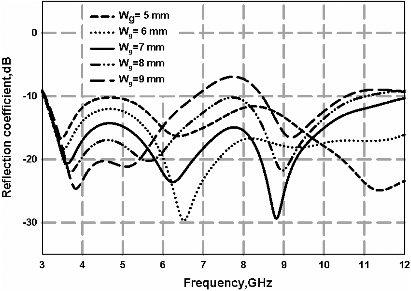
In the third and the last parametric study, the width of the ground plane W G is varied from 5 to 9 mm in 1 mm steps. The effect of variance of this parameter on the reflection coefficient of the proposed UWB antenna is depicted in Fig. 6. It can be seen that the ground width significantly affects the matching bandwidth of the antenna. Poor matching is observed in the lower end of the UWB frequency range for W G = 5 and 6 mm. On the other hand, poor matching is observed around the middle of the operational frequency range for W G = 8 and 9 mm. The only value of the selected W G range that provides a good matching performance is W G = 7 mm. It is worth mentioning that variation of the parameters L G and T is of negligible influence on the antenna performance. Thus, the parametric studies of these two were not included.

Fig. 6. Effect of ground width W G on the reflection coefficient of the proposed UWB antenna.
IV. DESIGN EQUATIONS
Design equations of the proposed FGCPW-fed UWB antenna are presented in this section. These equations are developed from the parametric studies discussed in the previous section. The goal of developing such equations is to provide reliable initial values of the parameters L G, W G, L 1, L 2, and T for any desired substrate. It is up to the user then to optimize these values to obtain the best possible performance. The design parameters in the design equations are given as a fraction of the guided wave length λ g which is given by:
where ε eff is the effective dielectric constant represented by ε eff = (ε r + 1)/2, and λ 0 is the free space wavelength at the center frequency which is set to be in the middle of the UWB band. More specifically, the center frequency f 0 = 6.25 GHz. The design equations were found to be as follows:
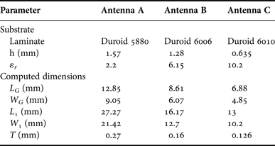
To verify the reliability of the proposed design procedure, three antennas with three different substrates are designed using (2)–(6). The computed dimensional parameters of each antenna are given in Table 1.
Table 1. Antenna description and computed parameters

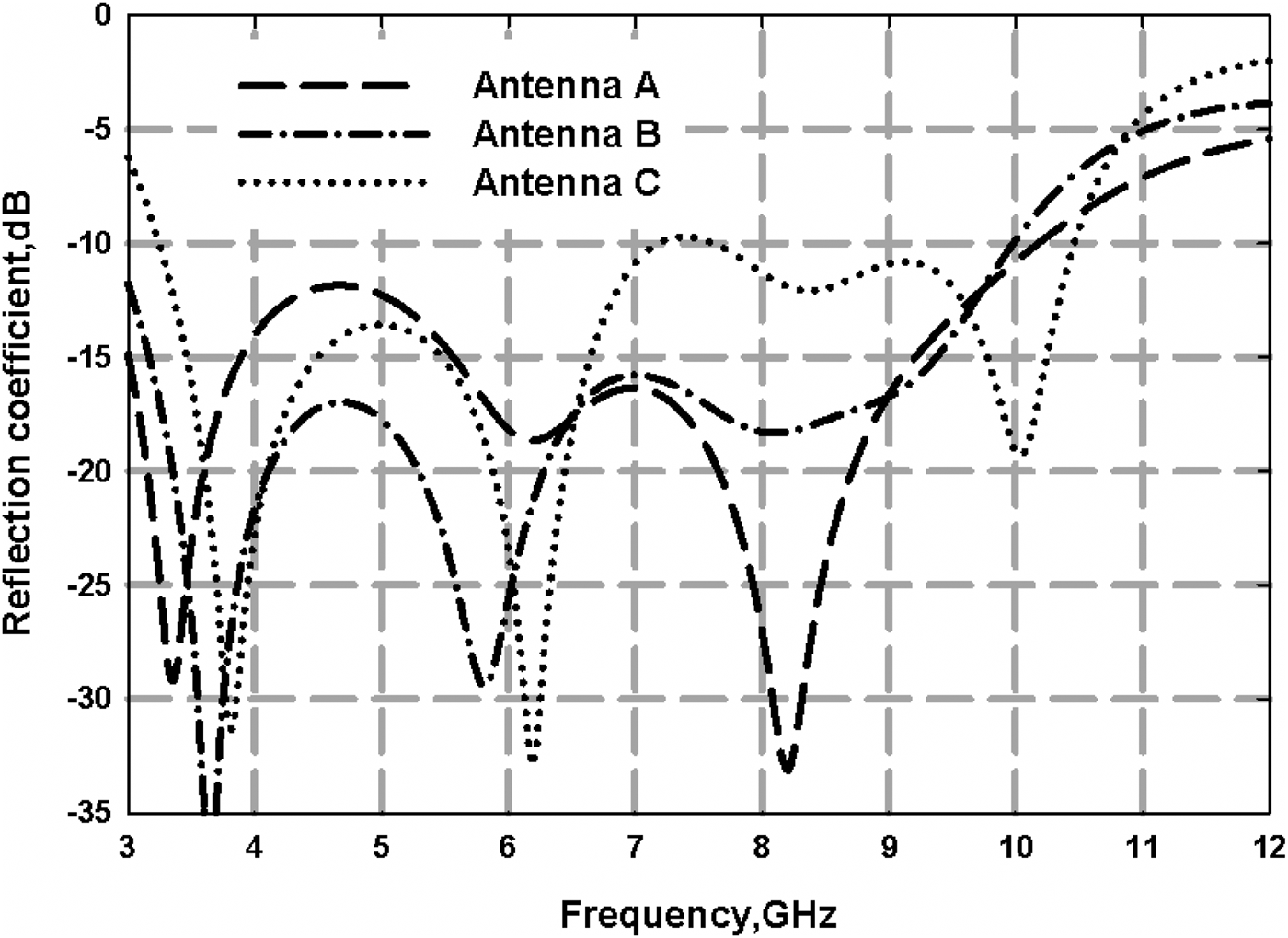
The reflection coefficients of the three antennas, which are given in Table 1, are shown in Fig. 7. It can be seen that all the antennas exhibit UWB performances that are close to what is required which means that the proposed design equations give good initial values for the design parameters. Obviously, further optimization is needed to reach the targeted UWB performance.

Fig. 7. Reflection coefficients of the three antennas given in Table 1.
V. EXPERIMENTAL RESULTS
To verify the simulated results a prototype of the proposed FGCPW-fed UWB monopole antenna, which was shown in Fig. 1(b), is fabricated on a 30 × 30 × 1.6 mm3 FR4 epoxy substrate having a relative dielectric constant ε r= 4.4. The dimensions of the fabricated antenna are the same as those given in Section II which are: L G = 10 mm, W G = 7 mm, W 1 = 14.5 mm, L 1 = 17.8 mm, W = 3 mm, T = 0.2 mm, and G = 0.35 mm. A photograph of the fabricated UWB antenna is shown in Fig. 8.

Fig. 8. Photograph of the fabricated FGCPW-fed flag-shaped UWB monopole antenna.
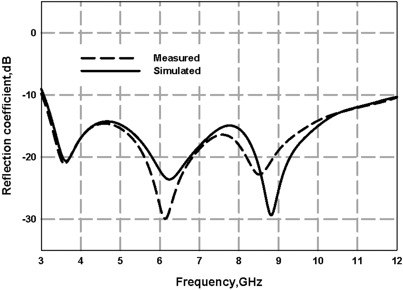
In Fig. 9, the measured and simulated reflection coefficients of the antenna are shown. It can be observed that the simulation and experimental results match very well. The −10 dB bandwidth is in compliance with the FCC regulations and ranges from 3.09 to 12 GHz. Also, it can be seen from Fig. 9 that the three resonances of the fabricated antenna have center frequencies of 3.45, 6.1, and 8.5 GHz, respectively.

Fig. 9. Simulated and measured reflection coefficient of the proposed FGCPW-fed flag-shaped UWB monopole antenna.
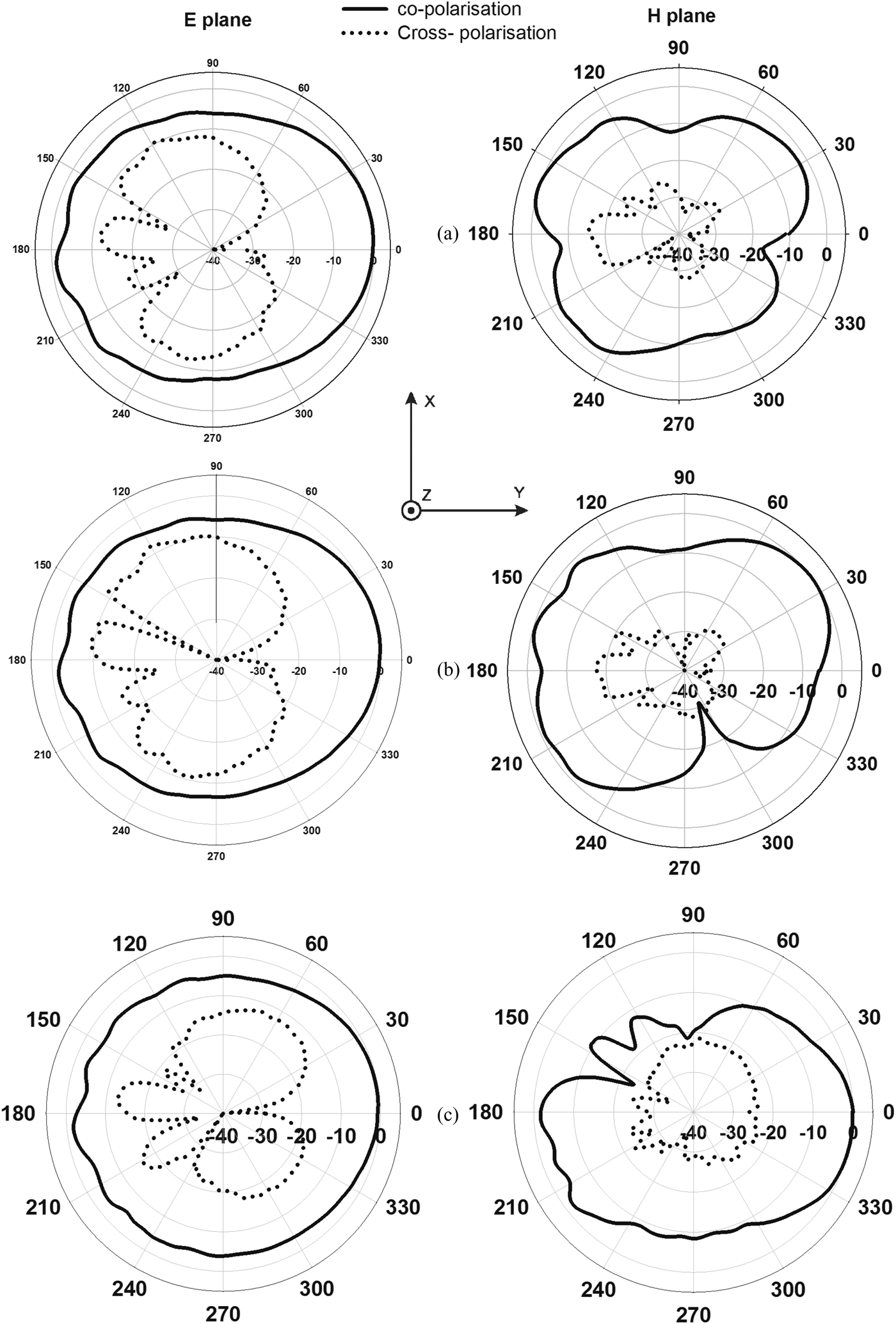
The measured principal plane radiation patterns of the proposed UWB antenna are plotted in Fig. 10. The patterns are measured at the center frequencies of the three resonances. In the E-plane, it is observed that the radiation is nearly omnidirectional, which is a typical feature of monopole antennas. The H-plane patterns, however, vary with frequency in the manner shown in Fig. 10. The proposed antenna exhibits an acceptable cross-polarization performance. It can be seen from Fig. 10 that the cross-polarization levels are generally low and do not exceed −9 dB.

Fig. 10. Measured radiation patterns of the proposed FGCPW-fed flag-shaped UWB monopole antenna at frequencies: (a) 3.45 GHz, (b) 6.1 GHz, and (c) 8.5 GHz.
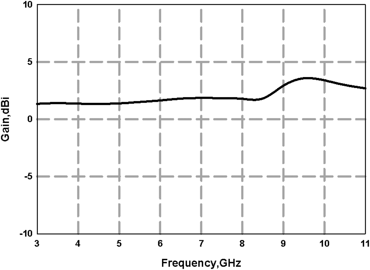
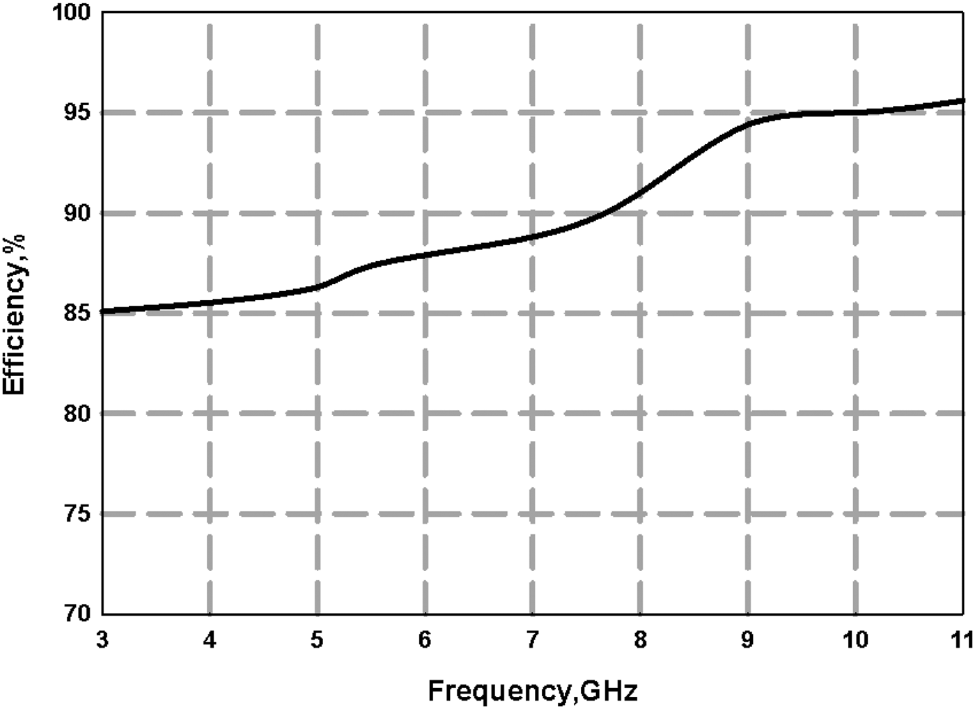
The measured gain of the antenna in the entire operational frequency band is shown in Fig. 11. It is observed that an average gain of 2.45 dBi is obtained for the proposed FGCPW-fed flag-shaped UWB monopole antenna. Radiation efficiency of the antenna is also measured using the UWB Wheeler cap method [Reference Schantz15] and is plotted in Fig. 12. An average efficiency of 91% is obtained for the proposed antenna.

Fig. 11. Measured gain of the proposed UWB antenna.

Fig. 12. Measured efficiency of the proposed UWB antenna.
VI. TRANSIENT ANALYSIS
In this section, the time-domain characteristics of the proposed antenna are discussed. First, the distortion introduced by the antenna is investigated. This is done by setting up a typical transmitting/receiving antenna system using two identical antennas each of which is the proposed UWB antenna. Then, the transmission coefficient S 21 is measured for the face-to-face and side-by-side orientations of the received antenna. The transfer function H(ω) is calculated from the measured S 21 for each orientation using the following formula [Reference Sörgel and Wiesbeck16]:
 $$H\lpar \omega \rpar =\sqrt {\displaystyle{{2{\rm \pi }Rc} \over {j\omega }}S_{21} \lpar \omega \rpar \, e^{\,j\omega R/c} {\rm \; }}\comma \;$$
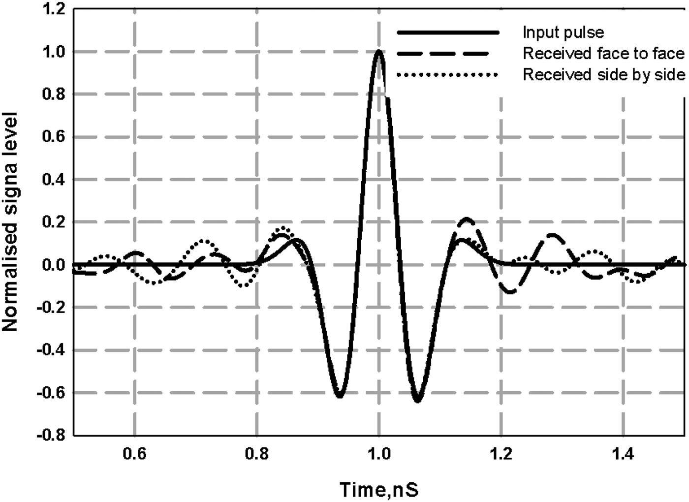
where R is the far-field distance between the transmitting and receiving antennas, and c is the speed of light in free space. The source pulse is selected to be a fourth-order Rayleigh pulse because its spectrum matches the entire UWB band directly. To qualitatively evaluate the distortion performance, the received pulses at the two orientations need to be calculated. This is done in two steps for each orientation. First, the inverse fast Fourier transform is applied on H(ω) and calculated from (7). The result is then convolved with the source pulse to obtain the received UWB pulse [Reference Chen, Wu, Li, Yang and Chia17]. In Fig. 13, the waveforms of the transmitted and received pulses are shown. By comparing the transmitted and received pulses, it can be observed that the received pulses maintain the shape of the transmitted pulse to a great extent. As a result, it can be concluded that the distortion caused by the antenna to the transmitted pulse is feeble.
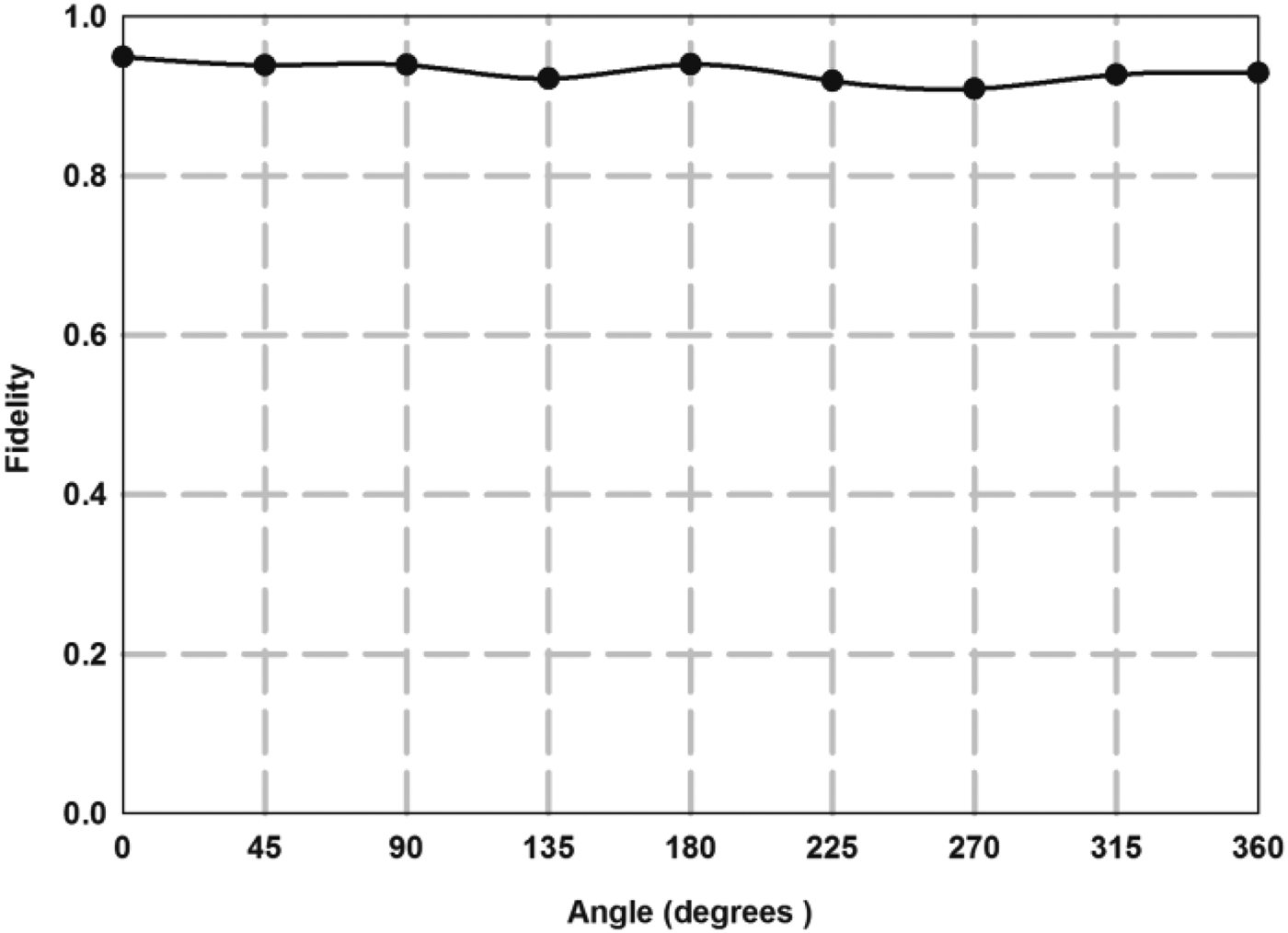
A figure-of-merit to quantitatively evaluate the distortion introduced by an UWB receiving antenna is the fidelity factor (FF) [Reference Ma and Jeng18, Reference Lamensdorf and Susman19]. Basically, it is the cross-correlation between the input and the received pulses. When the value of FF is unity, the input and received pulses are identical, and no distortion occurs. The FF is a function of the received antenna's orientation. In our case, the FF is measured in the H-plane (θ = 90°) for ϕ between 0° and 360°, and the result is shown in Fig. 14. The value of the FF is greater than 0.9 in all measured orientations which supports the conclusion made earlier that the proposed antenna introduces minimal distortion effects to the transmitted signal.

Fig. 13. Waveforms of the input and received pulses.

Fig. 14. Measured FF of the antenna.
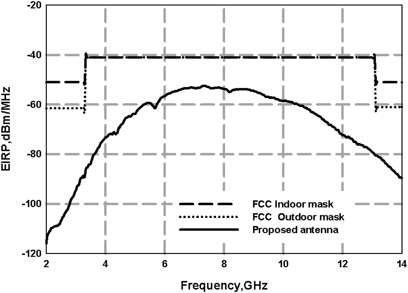
The radiation limits set by the FCC for indoor and outdoor data communication applications are expressed in terms of the effective isotropic radiated power (EIRP). Therefore, the EIRP of the proposed UWB antenna needs to be calculated to check whether it complies with the FCC regulations. The face-to-face H(ω) of the transmitting/receiving antenna system, which was computed earlier, is essential to the EIRP calculation. The EIRP of the proposed antenna can be found using the following expression [Reference Mirshafiei, Abtahi, LaRochelle and Rusch20]:
where f is the frequency of operation and P T(f) is the transmitted pulse power level. The EIRP of the proposed UWB antenna is calculated and compared to the FCC indoor and outdoor masks as shown in Fig. 15. It can be asserted from the comparison that the EIRP emission level of the proposed UWB antenna is FCC-compliant.

Fig. 15. EIRP emission level of the proposed antenna.
VII. CONCLUSION
A novel design of a compact FGCPW-fed flag-shaped UWB monopole antenna is presented. The proposed antenna covers the full UWB bandwidth with stable radiation pattern and constant gain throughout the band. Simple design formulas are developed, so that the designers can easily reproduce the antenna for different substrates. Transient analysis of the antenna reveals that the proposed antenna has excellent pulse handling capabilities. Also, the EIRP emission level of the antenna is FCC-compliant. The antenna has a compact dimension of 21.85 × 28 × 1.6 mm3 which makes it suitable for future wireless UWB applications.
ACKNOWLEDGEMENTS
The authors would like to thank the reviewers for their constructive suggestions. This work was supported by Kuwait University Research Grant no. [EEO2/12].


