1. INTRODUCTION
Computer-aided functional modeling has been a concern for researchers
since the 1970s (see Kuttig, 1993, sect. 2, for
four references from 1971 to 1974). Graphical function modeling, made
possible by progress in computer technology, is used in Kuttig (1993), where an example of computer-based functional
modeling for conceptual design with a rich model of flow-based function
structures is described. The transition from a functional description
(which is suitable during conceptual design) to parametric models (which
are suitable for embodiment design) has been identified as an important
research question. This problem is stated and addressed, for example, in
Yekula et al. (2003), where a method for the
construction of parametric models from functional models is presented.
Even the research behind this article aims at integrating functional
models and synthesis based on these functions with parametric analysis
models. The use of constraints to couple different partial models of
several engineering domains in embodiment design is described in Kleiner
et al. (2003), and the feasibility of such a
constraint interlinking approach is shown. Previous research on the topic
has also suggested the use of function/means trees (F/M trees) in
a combination with constraint networks in order to support interactive
conceptual design (O'Sullivan, 2002a, 2002b). The use of the expert system shell
CLIPS and F/M trees to produce concepts (schemes) and simulation
models from library elements by linking them in bond graphs is described
in Bracewell and Sharpe (1996), but relies on
the existence of a closed set of building blocks from which concepts can
be combined and uses calculation mainly in later phases in the form of
detailed Dymola simulation models. Support using an incremental constraint
network, with a focus on structural modeling, is described together with
the SyDeR tool in Feldkamp et al. (1998).
Constraint networks, spanning continuously from requirements to the
product structure, are used in the function oriented product model that
can be found in Leemhuis et al. (2002). The two
latter systems do not focus on a detailed model for multiple concepts and
solution principles.
The objective of the work described in this paper is to use
incremental constraint networks to quantitatively model evolving,
incomplete concepts during conceptual design. This is combined with a
hierarchical F/M tree (see Hansen, 1995) for
the qualitative aspects. Functions are entities used to describe a general
and intended relation between their input and output parameters with the
aim of fulfilling a task (Pahl et al., 2003),
and thus express necessary functionality. Means state how (by which
solution principles) this functionality actually is achieved. The main
focus is on early calculations involving relations on the few parameters
that are of conceptual significance, rather than on the deduction of more
complete models suitable for detailed calculations in later phases. The
quantities that can be used in calculations are not limited to energy
quantities, but can be any parameter (e.g., weight, cost, transmission
ratio, etc.). The artificial intelligence (AI) technology of constraint
networks is not an object of research in this work; it is merely applied
to achieve the actual contribution: a model, working procedure, and tool
constituting more suitable support for the early phases of engineering
design. The tool can be used to support solving complex engineering
problems. By allowing both qualitative (e.g., textual descriptions,
relations such as “function is solved by means” or
“means needs specific subfunctions”) and quantitative contents
(e.g., parameters such as the size of the solution element “electric
motor”), traditional design methodology, AI techniques, and
numerical analysis can be combined.
In this article, functional representations are thus used to do the
following:
- describe the interrelationship of functions and requirements;
- describe the function structure of the product that is to be
designed, that is, desired functionality (e.g., that a function
“provide torque” must be performed);
- describe the vertical structure, that is, the functional
decomposition (e.g., that the stated function is decomposed into
“create rotational movement” and “multiply
torque”);
- describe the horizontal structure, that is, how different functions
are interrelated by flows (e.g., output of “create rotational
movement” is related to input of “multiply torque”)
quantify functions to achieve better verified concepts (e.g., the size,
weight, etc., of the motor to provide the necessary torque depending on
the actual concept);
- provide a link between desired and achieved functionality (e.g.,
which other means could be used, which one is chosen); and
- support the storage of principle solution elements in a design
library and their reuse.
2. SUPPORTING CONCEPTUAL DESIGN
This section describes insights from design methodology related to
conceptual design and their implications regarding the intended
support.
2.1. Background
According to design methodology (e.g., VDI,
1997; Pahl et al., 2003), the steps
carried out during conceptual design are identification of an overall
function, decomposition into a number of subfunctions and a search for
solution principles. Solution principles are identified for all functions,
according to VDI (1997) with regard to both
effects and shapes (see Fig. 1). The figure
shows the steps in conceptual design (shown as rectangles), the databases
that can provide appropriate input information during the steps
(cylinders), and the results of the respective steps (parallelograms). The
arrows on the right indicate that iterations back to earlier steps are
possible; the arrows on the left show that requirements both affect and
can be affected by all steps.
The conceptual design and access to knowledge bases. Adapted from VDI
(1997, fig. 3).
Conceptual design thus progresses from requirements to functions, from
functions to their subfunctions, and from subfunctions to solution
principles (means), which then, after sufficient decomposition, are
combined to form overall principle solutions (concepts). This concept
synthesis is achieved by combining several effects or mechanisms into an
overall principle solution (cf. the arrow from
“effects”/“kinematic mechanisms” and
“3.1”/“3.2” to “principle
solutions” in Fig. 1). The focus in this
article is on steps 2.1–3.1.
2.2. Aims
The aim of this work is to provide a model for conceptual design,
constituting a partial model for concept development in a larger product
model. At present, sophisticated models and support are available for both
earlier and later stages, that is, requirement handling and embodiment
design [e.g., geometry modeling using commercial computer-aided
design (CAD) modelers]. At the transition between conceptual design
and early embodiment design, work has also been done on engineering design
synthesis, for example, the tool for compositional synthesis of mechanisms
FuncSION described in Chakrabarti (2002, chap.
11). On the other hand, apart from some academic or special-purpose
systems, no software support is available for innovative conceptual
design. In addition, many systems that might be used for conceptual design
(e.g., computerized design catalogs as outlined in Birkhofer and Keutgen,
1999, and Franke et al., 2004, Tech Optimizer as assessed in Lindemann et al.,
1998, etc.) are powerful when providing
solutions, but neither allow the instantiation of suggested solutions,
that is, adaptation to the actual task at hand, nor support the continuous
synthesis of the suggested solutions into an overall solution inside the
system.
Another purpose of this work is to enable a tool that allows
explorative, creative conceptual design even when carried out with
computer support. Using software to assist with operations such as
maintaining information for added means, selecting/deselecting means
in concepts, choosing values, and evaluating how the chosen values affect
requirements, the time and effort needed to perform routine tasks can be
reduced, while the designer can simultaneously carry out creative
steps.
One aim of such computer-supported conceptual design is to be able to
handle and compare multiple concept variants, which is suggested by design
methodology (Pahl et al., 2003, sect. 2.2.4).
Using computer support, more alternatives can be evaluated in a given
time, and quantitative support permits the degree of requirement
fulfilment of several concepts to be assessed. Reaching better-verified
concepts is facilitated by performing early calculations on a number of
parameters that are of conceptual significance.
Furthermore, a well-defined model and functional representation are
prerequisites for meaningful reuse, which can yield additional time
benefits.
2.3. Support approach
The basic approach to accomplishing support for conceptual design is
to apply the well-known F/M tree for qualitative modeling and combine
it with constraint networks for quantitative modeling. An overview of the
used elements is given in Figure 2 (for a more
detailed description of the elements, see Section 3). The functional
decomposition is modeled using a hierarchy of functions (cf. 3.2) and
means (cf. 3.3). Parameters (e.g., L and
Pi), accounting for the quantitative
description, can be assigned to both functions and means. Requirements
(cf. 3.1), grouped in dimensioning cases (cf. 3.7), are assigned to the
relevant parameters. Relations between parameters are modeled using
constraints, shown as dashed lines (cf. 3.5). Operating states (cf. 3.7)
can be used to group several functions that are active only for certain
time periods or under certain conditions. Concepts are obtained by
selecting one means for each function (cf. 3.6). For clarity, only two of
the “is contained in” relations between concepts and means are
shown (as dotted lines) in Figure 2.
The elements and relations of the support for conceptual
design.
The support is also suitable for innovative original design problems,
which require a broad variety of alternative means. Both analysis and
synthesis steps can be supported. The support is suitable for problems
that are possible to characterize by parameters and algebraic constraints
between them, that is, static calculations. Tightly coupled systems or
dynamic calculations, which, for example, occur in many mechatronic
systems, are not efficiently supported unless they can be simplified into
static calculations.
By introducing means, modeling using solution elements and reuse of
earlier realized, well-proven solutions is made possible.
2.4. Requirements on the support
Several requirements with regard to support software, which have been
identified in prior research, are also relevant to the present work.
Kuttig (1993) mentions the high information
turnover in conceptual design, and that a tool therefore must provide
abstract visualizations. Shifting between different types of information
(e.g. text, geometry, formulae or structure) and several methods for
modeling are required. According to Feldkamp et al. (1998), there should be no restriction to a fixed set
of components, as technical progress requires extensibility. A graphical
editor and a simple user interface that can be used by all engineers are
needed. Reuse of larger elements (over and above simple components) should
be possible. The working procedure should be interactive and allow
structural decomposition into smaller, more manageable subproblems. It
must be possible to iterate steps and revoke earlier decisions. In
Leemhuis et al. (2002), mentioned requirements
are that the tool should reduce costs, accelerate design, allow
modularization and reuse, and that it covers all phases from requirements
to part modeling. Domain-independent applicability to many products and an
incremental, iterative procedure are required. A clear description of
interrelations between requirements, function and structure, handling of
and free choice between alternative variants, handling of incomplete and
inconsistent specifications, and the availability of abstract views of
early designs are named as issues. Even here, possibilities to revoke
decisions and an arbitrary order of steps are called for, as well as
change propagation, decomposition and reuse. In Bracewell and Sharpe
(1996), the automatic deduction of exact
simulation models using bond graphs is a requirement that was fulfilled,
at the cost of functions needing to be standardized and limited to a
predefined library.
In this work, the main requirement is to provide a tool for innovative
concept synthesis that will enable to both work with principle solution
elements and early calculations. The model must be continuous (i.e.,
relations are possible in several steps from requirements to concepts) and
bidirectional (i.e., qualitative and quantitative descriptions are coupled
and updated in both directions). Qualitative and quantitative descriptions
are integrated: changes in means modeling are, for example, reflected by
adding or removing constraints and changed values are reflected by
updating properties of means or requirements. The model is separated into
partial models, that is, one piece of information is only stored at one
location to facilitate modularity and exchangeability. Additional
requirements that are of concern are to offer methods for flexible work
with solution principles in alternative concepts, reuse of solution
principles (not only components), explicit storage of principle variants
as concepts, and work with incomplete and inconsistent data at any stage.
Another requirement is that the model must be generally applicable to a
broad range of products. Functions, means, and parameter types are not
limited to a predefined closed set, but can be extended individually.
2.5. Working procedure
To achieve an efficient tool, the design of the tool and the working
procedures when using it must harmonize with the users' mental
models. To be suitable for conceptual design, the working procedure was
therefore chosen to be largely interactive and incremental. The individual
steps can be performed in arbitrary order (the only deliberately chosen
restriction is that means cannot be added prior to the function they are
to fulfill). The major steps in the procedure involve the following:
- task clarification: specification of the task by stating a number of
necessary requirements;
- abstraction: the requirements are translated to desired
functionality by defining a number of functions and adding them to an
initially empty document with only the root function present;
- incremental realization and decomposition: an F/M tree is built
using appropriate means and subfunctions;
- quantitative information: once the qualitative structure has been
established, quantitative information can be added at any time and for any
hierarchy level by describing functions and means using parameters;
- relations: adding constraints between parameters will then enable
modeling of the relations and change propagation; and
- concepts: finally, concepts as overall solutions can be chosen from
the set of modeled means, and quantitatively detailed by choosing values,
which may be concept specific.
These major steps outline an iterative procedure from requirements to
quantitatively verified concepts. Inside the major steps, there is a
succession of specifying, solving, changing (including change
propagation), and assessing operations. It is possible to create, modify,
and assess several variants during each step. The major advantage compared
to traditional configuration design operating on parts is that even
different principle solutions can be modeled by introducing functions and
means.
Regarding the envisaged use of the tool by an engineer, it can be
stated that the system is intended to constitute an assisting system. The
aim is not to provide an automatic system that would allow the synthesis
of complete solutions solely from a specified list of requirements. In
Table 1, the supported steps and the actions
performed manually by the designer as well as the actions automatically
performed by the tool are given.
Interplay of the tool and the designer using it
The tool is thus based on the assumption that the computer is used to
assist by automating routine tasks, such as constraint propagation or
activation/deactivation of subfunctions, depending on the chosen
means. The complex decision steps (e.g., identification of suitable
interelement constraints) are not automated but carried out by the
designer, although there are opportunities for further automated steps
(e.g., automatic combination and evaluation as outlined in Wilhelms & Derelöv, 2004).
3. A PARAMETRIC INFORMATION MODEL FOR
CONCEPTUAL DESIGN
This section describes the information model used to formalize
conceptual design. Figure 3 shows how the chosen
model objects in the lower part correspond with the phases and phenomena
described in VDI (1997) in the upper part, which
was chosen as background theory. The models for requirements, functions,
means, and concepts have been built as partial models without
intersections, that is, a concept description contains no functional
description; it merely references the functions it includes.
The structure of the information model elements, interconnecting
constraint network, and correspondence to VDI 2221.
The constraint network can connect all occurring objects from
requirements to concepts. The dotted objects on the right-hand side are
not yet implemented in the prototype implementation, but are shown to
illustrate that even parametric geometry models can be connected in a
similar way.
The Unified Modeling Language class diagram in Figure 4 gives a more detailed overview of the
information model. The figure contains the classes for modeling the
F/M tree (Function and Means), parameters and constraints
(Parameter/Variable; ConstraintNetwork; Constraint; FormulaParser,
which calculates numerical values during constraint propagation; and
MapleConnect, a link to the commercial symbolic math software Maple, which
is used to solve equations for the necessary variable), concepts (Concept
representing one overall principle solution, Realization representing one
means choice, and Assignment representing one value choice), grouping of
functions and requirements (OperatingState, DimensioningCase), and the
possibility to store justifications [Truth Maintenance System (TMS),
Justification, Node]. All the objects belonging to the actual design
task are stored in a Document object.
The information model as Unified Modeling Language class
diagram.
Even though the implementation of the justification-based TMS (Doyle, 1979) permits a more extensive use, the TMS is
currently only utilized for storing and managing justification objects. A
justification object is automatically created or updated for each
constraint that is added or modified, with the justifications carrying
information about the reason why the constraint exists. For an equality
constraint, reasons could involve, for example, a reference to the
physical law behind the equation or the way a structure is arranged (e.g.,
serial or parallel architecture resulting in an identity or a sum
constraint for a fluid flow rate). For a value assignment, the
justification contains the reason why the specific value was chosen, for
example, a reference to empirical data for a coefficient of friction.
Reasons are stored in the form of textual information with semantic value
only to the designer. So far, there is no active use of the TMS exceeding
this recording of justifications. The tool could, however, be extended to
apply justification objects to resolve inconsistencies with conflicting
constraints by dependency directed backtracking in a similar fashion as
described in Feldkamp et al. (1998, sect.
7).
3.1. Requirements
Requirement objects describe functional requirements or restricting
requirements. Functional requirements are assigned to a function's
parameter, in this way declaring the function responsible to deliver the
required flow, for example, to create a certain output torque. Restricting
requirements limit a parameter value, for example, the largest possible
motor size given by the available space, into which the mounted motor must
fit.
The requirement contains a value for the desired value, and the design
model (function) provides a value for the actual value the design in its
current state delivers. In this way, requirement fulfilment can be
checked.
Requirements of different types (exact value, interval) and strengths
(desire, requirement) can be modeled (Pahl et al., 2003, chap. 5).
3.2. Functions
As widely recognized (Kuttig, 1993; VDI, 1993; Leemhuis et al.,
2002; Pahl et al., 2003), functional
modeling is an essential part of conceptual design and is a prerequisite
for modularization, varying the solution principle using more abstract
function information and reuse. The functional representations used here
are both a hierarchic decomposition and a flow-based function structure.
Functions express purposes of the artefact by stating desired or required
behavior.
According to VDI (1993), a function is the
relationship between the input and output flows and the state variables of
a system, described independently of a particular solution. The
quantitative representation here uses a function object with connected
flows. Each flow, either input flow, output flow, or internal parameter,
is represented by a parameter object connected to the function. A textual
description of the function by verb and noun is also possible. The
qualitative representation is achieved by assigning a set of means capable
of fulfilling each function to it.
3.3. Means
A means is here used to model one way of achieving functionality.
Means also have assigned parameters, and internal constraints are used to
quantitatively describe the effect on which a means is based (e.g., the
relation of input and output torque for a pair of gears).
As different means may require different subfunctions, means can
contain links to specific subfunctions, that is, subfunctions that are
only active when the means is selected into the current concept.
The basic idea is that using a division into functions and means, only
those parameters can be modeled that are of conceptual importance for the
actual task. As not all of the properties of means that might be modeled
are equally important, the parameters that were chosen when modeling the
functions determine which of the means' parameters are exposed to the
environment, a selective approach similar to Langlotz (2000, pp. 90–91).
3.4. Parts
Parts are objects that serve as placeholders for externally modeled
geometry, for example, in CAD systems. Even here, parameters such as
geometric dimensions can be connected to the constraint network.
3.5. Constraints
Constraints are applied to model quantitative relations to enable
early calculations. As in Leemhuis et al. (2002), constraints span across different partial
models from requirements to concepts and geometry. Five different types of
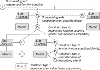
constraints are used to interconnect the elements (see Fig. 5).
The constraint types available in the tool for modeling
relations.
Value assignments (constraint type 1) are used to assign a definitive
value to a parameter. These value assignments are concept specific; the
same means can thus have different parameter values when they occur in
different concepts. Constraint type 2 connects requirements and function
parameters. Internal constraints (type 3) are used to describe the
physical effects a means is based upon. External constraints model flow
between different functions (type 4a) or collect properties from a
means' subfunctions (type 4b). All these constraints are added
manually and subsequently activated or deactivated automatically,
depending on the chosen means. In contrast, constraints of type 5 are set
automatically and model the identity of a corresponding function and means
parameter.
3.6. Concepts
Leemhuis et al. (2002) state the need to
explicitly document concepts, and they note that available commercial
software offers no satisfactory support for concept modeling. For this
reason, concepts are a central part of the information model presented
here.
A concept is an object that encapsulates a number of means choices and
a number of value choices. In this way, concepts can be used for a
parametric description of an overall principle solution to the design
task.
3.7. Operating states and dimensioning cases
The constraint network is used to describe relations between
parameters. To facilitate modeling of products that are more complex,
compound objects can be constructed by grouping several objects, which
then can be treated as a single entity. An example of this is to group
several functions into operating states or several requirements into
dimensioning cases (cf. Fig. 2). When doing so,
a whole group of requirements can be activated or deactivated by simply
changing the dimensioning case under consideration.
4. THE CONCEPTUAL DESIGN TOOL
To implement the information model described in Section 3 and to
verify its suitability in principle, a software prototype has been
implemented as an engineering application of constraint networks for
computer-supported conceptual design.
According to Kuttig (1993), computer-aided
functional modeling involves a product model; methods for modeling,
analyzing, selecting and evaluating; design databases; and communication
with the designer. In this section, the product model, a computer-internal
representation of the information model presented earlier, is described in
terms of these aspects.
4.1. General architecture and product model
The general architecture of the prototype is shown in Figure 6. The product model of the conceptual design
modeler is realized as an object-oriented C++ document-object model in
primary memory. It is visualized using the Microsoft Foundation Class
library. Persistent storage of models is made possible through
serialization, and independently of this, a design library in the form of
a relational database enables storage of means for reuse. The product
model can be exported into and imported from an XML document, and views of
the product model can be saved as bitmap or vector graphics.
The architecture of the prototype.
The applied constraint solver is DeltaBlue (Freeman–Benson et al., 1990), an incremental
constraint solver well suited for working with incomplete, possibly
contradictory concepts. Constraints are entered in symbolic, implicit form
(e.g., a = b + c), and external commercial
symbolic algebra software is used to solve the necessary explicit forms of
the equation for each variable (e.g., solve for b = a
− c).
The constraint network is used to model the quantitative relations
between parameters. Different strengths are used to model constraints. The
strength “required” is applied to link a requirement variable
to a function variable, for definitive user-made value assignments,
user-defined formula constraints, and automatically set identity
constraints between corresponding parameters of function and the selected
means. The strength “preferred” is applied for facultative
user-made value assignments. “Weak default” is used to set
initial values. The structural, qualitative relations in the model, for
example, that a number of means belong to a specific function, are
realized using pointers between objects.
4.2. Manipulation methods and operations
The C++ objects described offer a number of manipulation methods for
the product model. All objects offer the usual
adding/removing/accessing member routines for their child objects,
for example, accessing the means belonging to a function.
In addition, concept objects (cf. Fig. 4)
offer a more complex event handler that is called when a concept is to be
activated or deactivated upon user request (functions
OnActivate() and OnDeactivate() in class
CConcept). This routine will activate or deactivate the
necessary means (by forwarding the call to
Select/Deselect() in the CMeans class) and set
or remove the necessary identity constraints between corresponding
function and means parameters (using
Create/DestroyConnectionConstraints() in the
CRealization class). When a subfunction during this operation
is deactivated, the external constraints of the function are moved to a
list of inactive constraints and removed from the constraint network. Upon
reactivation, these constraints are restored from the list and written
back to the constraint network. When a means is deactivated, its current
parameter values are stored in a list for future reference when it is
reactivated (using Save/RestoreParameterValues() in class
CRealization). In this way, even parameter values that have no
definitive value assignment are preserved. Furthermore, all means and
subfunctions below the actual function are recursively activated or
deactivated.
4.3. Storage to database, search, and reuse
Hirtz et al. (2002, appendix A) provide a
taxonomy for functions and flows. Flows are divided into categories such
as liquid flow, effort flow, or pneumatic air flow caused by pressure. The
design library in the present work is based on similar thoughts, but for
constraint networks to be applicable, the flows are expressed by a set of
standardized parameters. For this purpose, the 24 IQ quantities from Roth
(1994, fig. 5.2) were chosen as parameter types
(see Table 2).
Roth (1994) defined IQ quantities as the
physical quantities that determine power (denoted as intensity,
“I”) or amount (quantity, “Q”). IQ quantities are
used as functional parameters that define the physical facts of the task,
that is, constitute parameters describing input and output of the desired
functions. The desired relation of IQ-quantities on a function's
input and output is thereafter actually achieved by choosing suitable
design parameters, defined as a realized design solution's physical
quantities that describe the direct relation between its IQ quantities.
For a desired function “Convert force to linear movement”,
with input IQ-quantity force (F) and output IQ-quantity
displacement (s), the principle solution “linear material
elasticity” could be chosen, with the material stiffness
(c) as the design parameter that connects force and displacement,
giving rise to the internal constraint F = c ·
s.
For this notation and the case that one of the 24 IQ quantities is
converted to another, a matrix of physical effects known to perform these
conversions is available in Roth (1994, sect.
5.5.2), and VDI (1997, sect. 4.2.2; see Fig. 7). Effect is hereby defined as physical,
chemical, or biological law, relation or phenomenon with which a desired
function can be performed. The effects in the matrix constitute an initial
basis for the design library. The IQ quantities are intended for use when
connecting functions' input and output flows, but do not constitute a
complete set that is able to express all necessary parameters. For
internal parameters describing the design quantities, additional types may
be used by adding user-specific types, for example, the transmission ratio
for a gearbox.
The functional parameter matrix (above) and excerpt of the solution
database for field 1.2 converting force to displacement
(below).
The design library is structured as a relational database with seven
tables (see Fig. 8).
The database schema as Unified Modeling Language class
diagram.
Storage to the database is performed by issuing a “store in
database for reuse” command on a means after it has been modeled in
the graphical environment. When processing the command, the modeled
functions and means will be entered into the database together with their
parameters. Internal constraints and external constraints within the scope
of reuse (i.e., from means to subfunctions and between subfunctions) will
be added to the database. Identifiers and pointers will be translated to
the database keys. The chosen method of data collection thus corresponds
to online knowledge capturing as described by Jensen (1999, p. 192), but with the advantage that the stored
models conserve their functionality (constraints continue to operate even
in reused models) and also allow reasoning to some extent (even if
directly creative steps are not supported).
Upon later reuse, which is initiated by issuing a “search
means” command on a function, a search for suitable means will be
specified using the input and output flows of that desired function. For a
function “multiply torque,” a search could, for example, be
specified by stating that the desired function has a torque both as its
input and its output; a free text search for the word “torque”
could also be specified. This query is entered interactively in a dialog
box and then automatically translated to the Structured Query Language
(SQL) statement shown in Figure 9. The resulting
means are then presented to the designer as a list of suggestions. The
corresponding F/M tree segment that includes the assigned constraints
can be opened and viewed for each suggestion.
The generated SQL statement querying the design library.
4.4. User interface
As already stated, functional modeling and computer supported
conceptual design have been a research concern for a long time. As pointed
out in Kuttig (1993), because of the progress in
technical development, the provided computer support evolved from
alphanumeric, difficult to handle systems to more suitable interactive
modeling with graphical user interfaces. This prototype also uses abstract
graphical views to let the designer interact with the underlying product
model.
The user interface was implemented using a splitter window, divided
horizontally into three areas. In the section on the left (see Fig. 10, left, which shows the example described in
more detail in Section 5), requirements are listed with desired and actual
values. The section to the right gives access to a list of suggestions for
reuse from the design library. In the middle section, one of several views
can be chosen to visualize and modify the product model. At present, two
views are available: a flow-based function structure view (see Fig. 10) and a hierarchical F/M tree view (see
Fig. 11). The function structure view contains
functions and the flows interconnecting them. The functions and
constraints are drawn automatically, whereas the designer is free to place
the functions at the desired positions. The F/M tree view is rendered
fully automatically. In this view, drag and drop operations are used to
move functions and means. When moved in this way, the model relations are
updated accordingly, for example, that a means receives another function
as its parent function. Both views provide access to the methods of the
individual functions or means using a context menu with different menu
entries depending on the actual object (e.g., reuse only for
functions).
A screen layout of the prototype with requirements (left) and function
structure view activated (middle).
A screen layout with function/means tree view activated
(middle).
Concepts can be generated flexibly by double clicking on means in the
tree view; the selected means will then be displayed with a red border. If
means have specific subfunctions (i.e., subfunctions that are only active
for a particular means), then the tree will be redrawn to show these
subfunctions. With the combo-box element in the toolbox at the top, the
designer can easily change between a set of alternative concepts. Here,
too, the tree will be redrawn to reflect the selections of another
concept.
If the constraint network is affected by any of the operations, it
will be updated. As means are selected or deselected, internal constraints
will thus be activated or deactivated and identity constraints be set or
removed. Value assignments will be set or removed depending on the chosen
concept. Requirement fulfilment is checked by comparing required value
(stored in the requirement) and achieved value (provided by the function
in the design) and will be displayed using a color code (green for
fulfilled requirements/wishes, yellow for violated wishes, or red for
violated requirements). During all steps, constraint propagation will be
performed to forward any changes.
Requirements and parameters are displayed as lines in grid controls
(cf. Fig. 10, left). For parameters, values can
simply be changed by entering a new value, which will then be kept as a
weak default (and may change until the designer chooses to constrain it
with a definitive value assignment). Even here, color coding is used:
values that are determined by other constraints and are not editable are
displayed in grey. Fulfilled constraints are shown in green, violated ones
in red.
5. EXAMPLE
As an example, a water hydraulic rock drill was modeled in the
prototype. This design example was taken from a live, company-ordered
design project (Adolfsson et al., 2002), which
was previously carried out by fourth-year mechanical engineering students
and supervised by the author. The conceptual design task was to redesign
an existing drill, so that it supported the reactive force and torque from
drilling inside the drilled hole instead of outside. Several principle
solution alternatives were suggested by the students in their project
work, in which they used a traditional F/M tree and separate
paper-based calculations. This design project has been used both for
developing the presented information model and tool, suitable for the
needs discovered during the project, and for providing an application
example.
Using the prototype described in this article, an F/M tree with
integrated early calculations was modeled for the drill example. The
F/M tree, as it is automatically rendered by the prototype, is shown
in Figure 12. The letter S to the left of a
function indicates that the function in question is a specific
subfunction, that is, it is active only as long as the means that it
belongs to (indicated by a minus sign inside a small function symbol)
remains selected (indicated by a thick border; red on screen display) and
is part of the current concept. Functions without an S are active
independent of the chosen means (i.e., are common to all means).
A function/means tree of a rock drill rendered by the
prototype.
The functions of the F/M tree are interconnected by flows, each of
which is represented by an external constraint (type 4a). Parameters in
the model are uniquely identified by their function name, followed by a
dot and the parameter name, for example, “Supply
water.Q” for parameter Q representing the output
flow in function “Supply water” or
“Drill.M” denoting the output torque M of
function “Drill”. The constraints are then entered using the
text strings given below. Figure 13 shows the
type 4a constraints for the first decomposition level related to water
flow and rotation. These constraints express the balance of input volume
flows (Supply water.Q = Remove mud.Q + Drill by
rotation.Qin + Feed.Q) and output volume
flows (Carry off water.Q = Remove mud.Qout +
Feed.Qout + Drill by
rotation.Qout) and that connected functions have the
same parameter values regarding torque and penetration speed (Drill by
rotation.M = Support reactive torque.M, Drill by
rotation.v = Feed.v).
A function structure with interlinking flows (each represented by one
external constraint).
An important issue that can be covered is the concurrent development
of hierarchical function structures and the F/M tree. The functions
“Drill by rotation” and “Feed” are for example
decomposed into four subfunctions each in the F/M tree (cf. Fig. 12). The same subfunctions can be found in the
function structure, located inside the boxes of the two parent functions.
In Figure 14, these subfunctions are shown, and
detailed by giving their constraints:
- type 4b constraint that connects the parameter
Qin in means “Rotating drilling head”
belonging to function “Drill by rotation” of level 2 to the
function “Create rotation” of level 3 (Qin
= Create rotation.Q) and in this way enables hierarchical
function structures by collecting the properties from subfunctions;
- type 4a constraints on decomposition level 3 indicating, for
example, that the weight on bit applied onto the drilling head is the same
as the force produced by the corresponding function (Create drilling
normal force.F = Drill.F); and
- type 5 constraints, for example, connecting the parameter v
of the means “Rotating drilling head” for function
“Drill by rotation” to the parameter v of the
function “Drill by rotation,” in this way connecting the
subfunctions' model to the level above.
A snapshot of the function structure in the prototype.
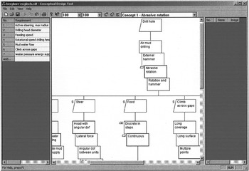
In Figure 14, the corresponding screenshot
of the prototype is given. It shows how an underdefined function structure
(the functions “Steer,” “Feed continuously,” or
“Climb across gaps” have not yet been quantified) already can
be used for quantitative modeling in some parts (in function “Drill
by rotation”). Functions are shown as rectangles with input flows on
their left edge, output flows on their right edge, and internal parameters
at the bottom. The number left to the function name indicates the
function's level of decomposition in the F/M tree. Connecting
lines represent the constraints.
The function structure is automatically rendered from the F/M tree
and constraint network information. The designer is free to move the
functions from their initial positions at wish, and, if applicable,
subfunctions will be moved together with their parent functions. Upon
changes in the F/M tree, the function structure will be updated, for
example, by automatically replacing the subfunctions if a means with
different specific subfunctions is chosen. The connecting lines
representing the constraints are drawn by the prototype automatically.
Internal constraints (type 3) describe how the chosen means achieve
the interconnection of input and output parameters. Internal constraints
are, for example, F = μ · FN for
the means “friction” or p = F/A
for “cylinder.” For the means “Rotating abrasive diamond
bit” associated with function “Drill,” internal
constraints indicate the following:
- a recommended penetration rate n/v
(rotations/cm), interlinking rotational speed n and rate of
penetration v, and
- the amount of created drilling dust Qd as a
function of the rate of penetration v (Qd =
v · πD2/4)
Value assignment constraints (type 1) are used to set values of
variables, for example, the necessary feeding force or weight on bit
(F = 30 kN, steered by the drilling head data), the estimated
friction coefficient (μ = 0.2) or the recommended rotations per cm of
the drilling head (n/v = 80
cm−1).
Requirement constraints (type 2) are used to relate requirements
(e.g., the necessary rate of penetration of v = 3 m/min) to
the corresponding function parameter (Drill.v), which allows
actual values to propagate to the requirement and enables to check the
requirement fulfilment by comparing actual and required value. By these
constraints, the connection between requirements and design parameters is
achieved. In a similar way, the other requirements on rotational speed
(n), diameter (D), flow (Q), steering radius
(R), gap length (L), and water pressure (p) are
connected to Drill.n, Drill.D, Remove mud.Q,
Steer.R, Climb across gaps.L, and Provide normal
force.p.
Identity constraints (type 5) are set automatically as soon as
concepts are created by choosing means. These constraints bind the
corresponding parameters of function and means, for example, “Create
drilling normal force.F = Cylinder.F,” and in this
way connect the two separate networks of external and internal
constraints.
The rock drill proved to be an example of a design task that is well
suited for support using the described methods and tool. Using this model,
easy conceptual decisions can be modeled and assessed, for example, which
consequences a different drilling head requiring other water flows or
speeds has for the other functions. However, it can also be seen that
conceptual modeling quickly become extremely complex when different
solution principles are involved, and a restriction is therefore necessary
on few parameters to avoid that concept modeling requires more effort than
it saves.
6. CONCLUSIONS
This article presents a way of supporting conceptual design with
regard to both concept synthesis and quantitative verification of concepts
using a hierarchical F/M tree decomposition and integrated constraint
networks. This work extends previous research on computer-supported
conceptual design and the use of constraint networks from other
researchers (Feldkamp et al., 1998; Leemhuis et al., 2002; O'Sullivan, 2002b).
The original contribution of the underlying research in this project
is to provide an information model for conceptual design that permits
parametric, constraint-based modeling of concept synthesis from solution
elements that are based on solution principles, not only on components,
subassemblies or parts. Specifically, in this article, the original
contribution is a method for using a database to store previous principle
solution elements for future reuse, where the separation from the old
context and the insertion into a new context is achieved by a division
into external constraints (type 4a, not reused, except for subfunctions)
and internal constraints (type 3, reused) and the use of special identity
constraints between corresponding function and means parameters (type 5)
that are easy to remove and reinsert. A whole tree segment including
subfunctions and parametric model can in this way be detached, stored and
reused, and in this way, reuse of larger principle solution elements is
made possible in a more flexible manner, and the library becomes
extensible. The basic ideas behind the prototype and a relational database
with SQL statements implementing the mentioned reuse are also
described.
The presented information model and the tool incorporating it
constitute an aid for supporting a discursive procedure for obtaining
verified quantitative concepts. In this way, support of early conceptual
design, taking into account different principle variants and alternative
concepts, is made accessible to computer support, and more concepts can be
evaluated and verified in the same time. Concept synthesis and early
calculations are integrated, and bidirectional propagation in change
operations is provided.
The tool supports incremental work, where all elements such as means
or concepts can be added and modified at any time. The elements do not
have to be fully defined from the beginning and can be individual, that
is, also not predefined. Parameters, constraints, and value assignments
can likewise be flexibly added, changed, or removed at any time to enable
an incremental, interactive and explorative way of working, which is
believed to be suitable for conceptual design.
During development of the tool, several realistic design problems from
prior company-ordered student projects in a fourth-year mechanical
engineering master's course (Engineering Design–Product
Development) have been used, and the model was designed to be able to
express them. The suitability of the model has thus been shown by
theoretic reasoning and self-observation while modeling the examples. The
practical applicability has not yet been further verified in setup
empirical tests on any realistically sized projects in companies. To reach
results beyond trivial observations and not to be too hampered by
prototype instabilities, this requires a fairly stable and implemented
prototype, which has not been available until recently.
It should also be noted that the supported part of conceptual design,
yet doubtlessly important, is only a small part of product design. There
are numerous other important activities beyond the scope of this tool, for
example, shape design and layout, aesthetic properties, or customer
perception that cannot easily be expressed by simple parameters, more
complex relations that cannot be expressed by simple algorithmic
relations, and so forth.