1.0 INTRODUCTION
The conference was held in The University of Liverpool's Foresight Centre on 8–10 November 2016 with a common language, ‘modelling and simulation in support of a rotorcraft's life-cycle’. Virtual Engineering (VE) was defined as the creation and use of Virtual Prototypes (VPs) to support decision-making throughout a product's life-cycle, which may be 50+years for a rotorcraft.
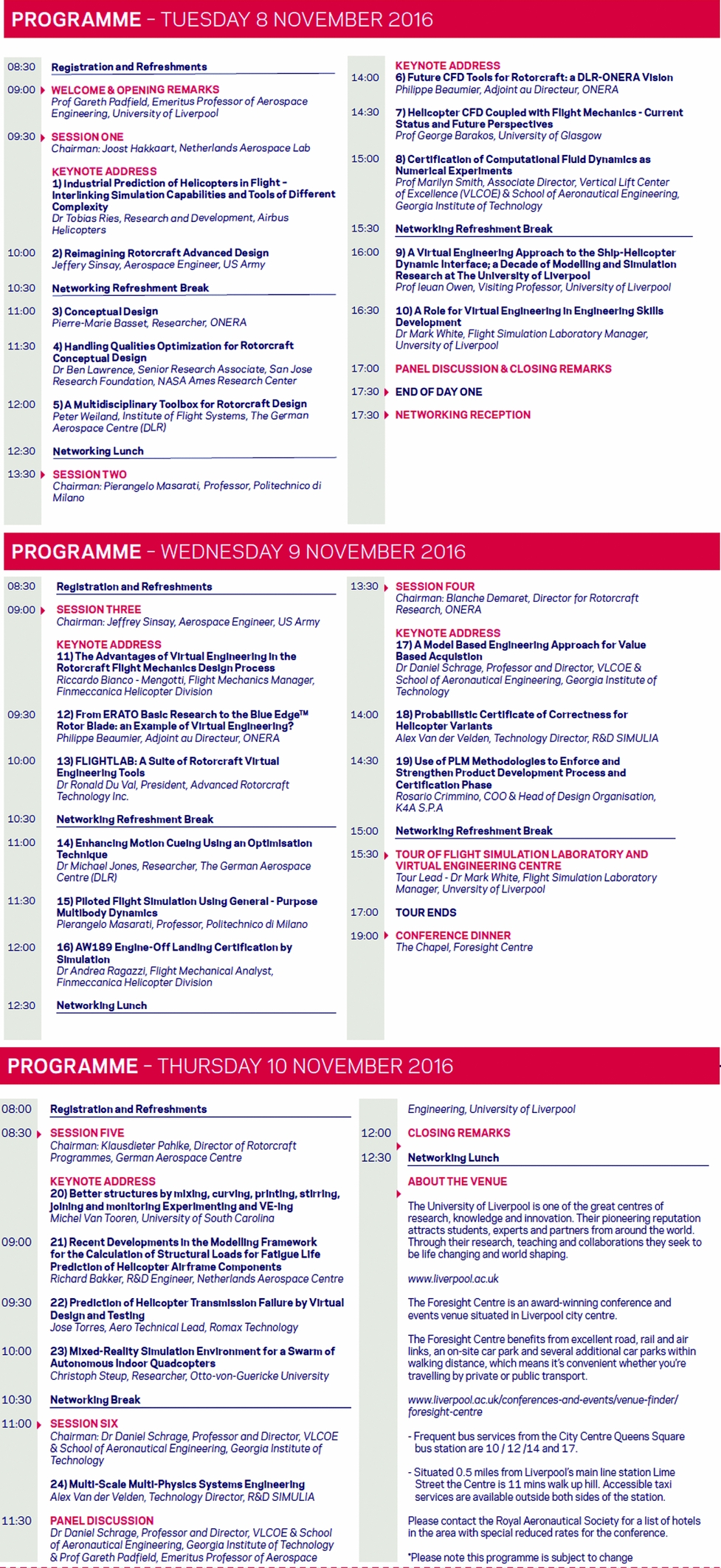
The conference comprised 24 papers,Footnote * including 6 keynotes, spread over 6 serial sessions in 2.5 days, with a technical tour of the University's simulation facilities, 9 networking breaks, 3 panel discussions and a dinner in the Foresight Chapel. The 50 delegates comprised industrial and government engineers, engineering managers and academics from 6 nations and 28 different organisations. The Appendix to this paper shows the conference programme; in this report, conference papers are referred to by their paper number as shown in the Appendix.
Mike Hirschberg, Executive Director of the American Helicopter Society International, opened the conference on behalf of the partner societies, handing over to the Conference Chair, Professor Gareth Padfield, to give the introductory talk. Padfield took us back 500 years to one possible birth of VE, or at least to the roots of the underpinning mathematics. Nicolaus Copernicus, a renaissance mathematician, formulated a model of the universe with the sun at the centre (heliocentric hypothesis). He described two kinds of mathematical modellers:
• Instrumentalists believe that mathematical models are used to facilitate calculations and to make predictions,
• Realists believe that a successful mathematical treatment reveals how things must be.
Both are needed in a modern VE team. Instrumentalists create product models to predict behaviour but these models can be so complex and the outputs potentially so confusing that we also need the Realists to create mathematical relationships that help us understand connections between cause and effect. The rotorcraft industry needs VE first to ensure decisions made early in the life-cycle, at the requirements capture and preliminary design, are reliably informed. Then later, in design, development and qualification, VPs can become the centre of attention for critical reviews and, ultimately, certification itself. A significant challenge is to ensure that model fidelity is good enough, not only for supporting design decisions but also in establishing requirements based on sufficiently mature technologies. This comes down to Verification and Validation (V&V), a topic addressed in many of the conference papers.
Figure 1 illustrates the general form of the cumulative percentage of life-cycle costs, both expended and committed. Seventy-five percent of a product's cost can be committed through the decisions made and actions taken in the first 10% of the life-cycle. If we consider the cost to fix problems in this first 10% as one unit, then the cost to fix grows by several orders of magnitude as the project advances. There are enough examples of such ‘failures’ across the aerospace industry that the case for investment in VE tools and capabilities is compelling. Padfield described an incident involving uncontained turbine blade failure on a commercial transport that led to behaviour and extensive damage that were not predicted by the manufacturer's modelling. The conference explored the status of a range of different kinds of VE tools and their effectiveness in application. The presentations were high quality and the delegation quickly became a community engaging with each other and the presenters, drawing out more and more detail and read-across from one area to another.
Figure 1. Committed and expended costs during the life-cycle of a product.
2.0 KEYNOTES FROM INDUSTRY
The keynote presentations by Airbus Helicopters (Ries and Schimke) (1) and Leonardo Helicopters (Bianco-Mengotti) (11) focused primarily on aeromechanics prediction. These were particularly important contributions to the conference as they provided a glimpse of the status and practice of VE applications in the rotorcraft manufacturing industries. Ries noted the constant trade-off between the use of fast and simple (lower-fidelity) and slow and complex (higher-fidelity) modelling in design and development, particularly for flight test support when schedules can be challenging. Coupled Computational Fluid Dynamics (CFD) and Flight Mechanics (FM) codes were commonly used to examine interactional aerodynamic issues. The Airbus Helicopters’ perspective is summarised in Figs. 2 and 3, showing a matrix of the different types of prediction methods, with simulation speeds, accuracies and application areas categorised.
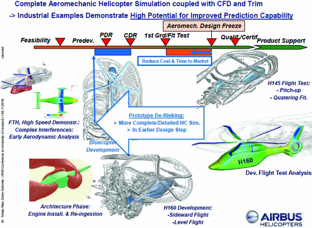
Figure 2. Schematic of Airbus's approach to coupling aerodynamics and flight mechanics simulation through the life-cycle (1).
Figure 3. Capabilities of different simulation methods – an Airbus Helicopters’ perspective (1).
The different methods were used selectively through the design and development life-cycle phases, with simulation results examined for indicators of “potentially problematic flight states”, e.g. high moment gradients, poor convergence, low control authority. This ‘indicator’ methodology worked well but needs expert scrutiny and should be “as general as possible”, minimising the risk that “the indicator definition is so special that other relevant interactions are ignored because they don't fit into the logic”. A comment made by one of the presenters during the discussion was that “we should aim to minimise the time between first flight and design freeze”. In an ideal world, these would be reversed of course; design freeze occurring before first flight. However, nobody was claiming that the helicopter industry has reached this level of maturity with VE predictive capability. The Airbus keynote stressed that current developments towards strong coupling between CFD and FM codes are necessary to address the challenges in the predictive capability for future helicopter developments.
The Leonardo keynote (Bianco-Mengotti) (11), The Advantages of Virtual Engineering in the Rotorcraft Flight Mechanics Design Process, introduced the triangle of advantages – safety, effectiveness and economy – that VE offers the aviation community, particularly helicopter manufacturers. A success story for the safety advantage was described relating to tail rotor failure, considered in the design of the AW169 helicopter, to ensure recovery was possible, and to provide guidance on the recovery techniques for pilots (Fig. 4). A second example was cited in the companion Leonardo paper (Bianco-Mengotti, Ragazzi) (16) addressing the ‘AW189 Engine-off Landing Certification by Simulation’. Piloted simulation was used to augment the flight data to meet the relevant CS-29 certification requirements. Validation against flight data was critically important in both these examples and the AW189 paper was particularly detailed in this aspect (e.g. Fig. 5). It was noted that the test pilot found the simulation realistic but with a higher workload than flight, providing a conservative result.
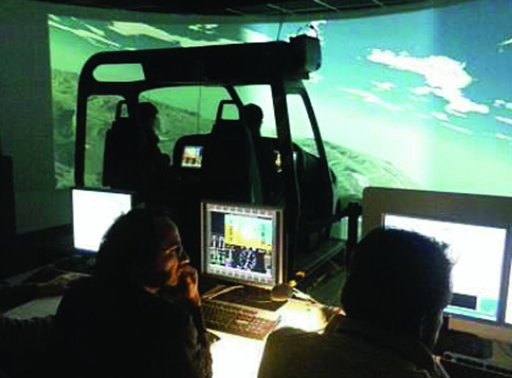
Figure 4. Image from the AW169 tail rotor loss simulation trials (Leonardo) (11).
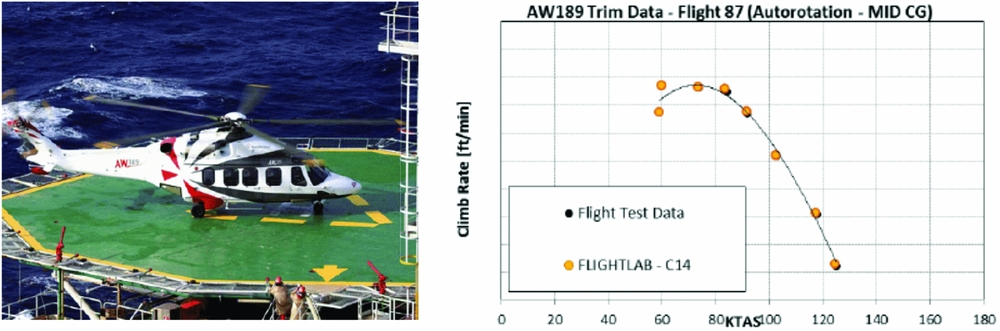
Figure 5. The AW189 with correlation of flight test and simulation for rate of climb in the mid-speed range showing good model fidelity (16).
Turning to the cost advantage, Bianco-Mengotti stated that the use of engineering simulators can reduce costs to below 10% of those incurred in flight test, not only for the emergency manoeuvres and failure cases described. The third advantage, effectiveness, was described in terms of the increased flexibility offered by simulation, compared with real flight, to explore the design space and ‘what-if’ scenarios. The simulation can also ‘measure’ parameters not always available in flight, offering specialists a greater understanding of the physical relationships between causes and effects.
The Leonardo keynote described the evolution of the use of VE by the rotorcraft industry in terms of the Roger's curve for the adoption of innovation, showing how innovators and early adopters shape a rising curve, followed by the decrease with late adopters and laggards (Fig. 6). Rotary-wing adoption was perhaps 20 years behind the fixed-wing community but an advantage was that the fixed-wing experiences can be capitalised on. As Bianco-Mengotti stressed in his keynote, “the technology is now in our hands and it's up to us to make the best use of it”.
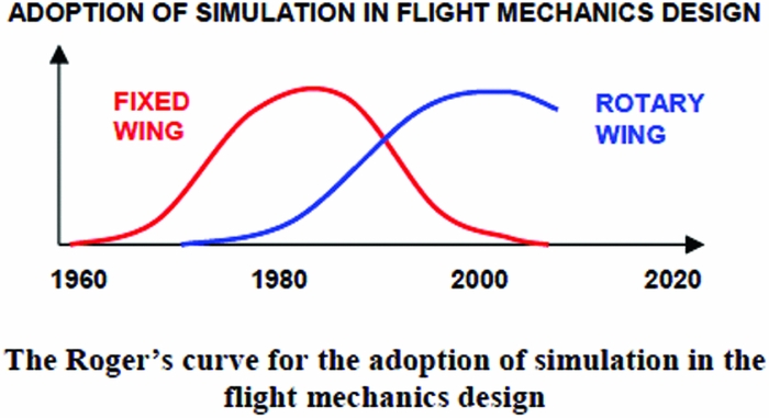
Figure 6. Adoption of simulation in design (11).
3.0 SKETCHES FROM THE TECHNICAL SESSIONS
Session 1 contained four papers from research centres on VE in conceptual design, with a recurring theme being the required model fidelity. Sinsay, representing the research arm of a major acquisition authority (U.S. Army), re-imagined the design in terms of reducing uncertainties in outcomes, categorising fidelity in different levels for different disciplines and emphasising the need for an integrated (disciplinary) design environment that enhances creativity (2). Sinsay elaborated on the uncertainty sources as analysis errors, model description errors and specification errors. The latter he cited as a significant contributor in this regard through “improper representations or understandings of user requirements, e.g. ‘all-weather capable’, ‘infinite life’, ‘zero maintenance’”; what exactly do these mean? He presented a comprehensive picture of the VE tools deployed in conceptual design (e.g. Fig. 7) categorised in three fidelity levels, with the catch phrase “right fidelity = matching model and analysis to the desired level of certainty”. Sinsay also used a similar construct to Fig. 1 to argue the importance of adding model fidelity early in the life-cycle.
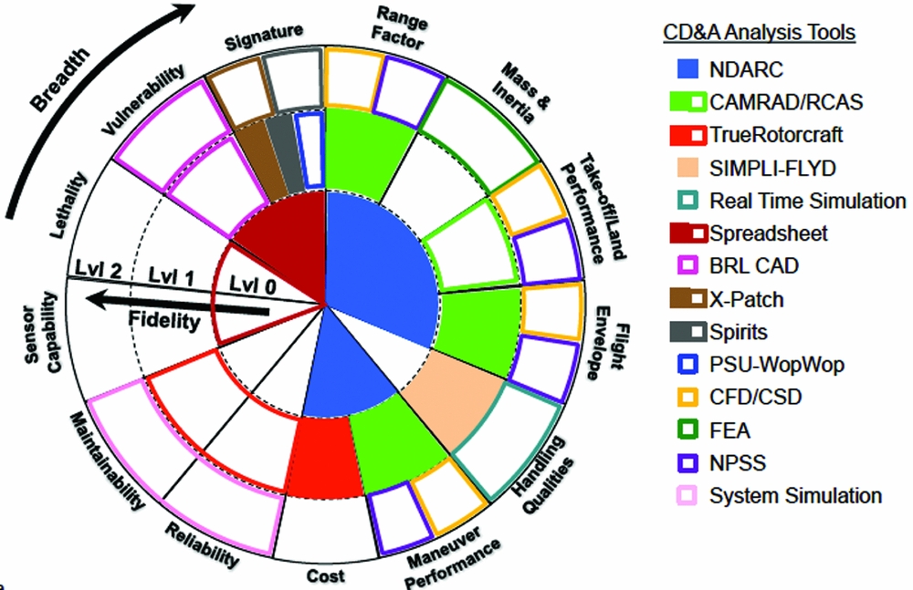
Figure 7. Analysis breadth and fidelity (2).
The two papers by Basset (ONERA) (3) and Weiand (DLR) (5) described the development of conceptual design models and processes at these two research centres. Both papers considered new rotorcraft in pre-design from a set of mission requirements, arguing that the cost in simulation time must be low enough for performing a large number of sensitivity studies and pre-sizing optimisation loops. Describing the ONERA toolset CREATION, Basset argued that high-fidelity was not required at this early stage but rather, “a better paradigm is ‘the more a model is adapted to the degree of description given by the available data, the more it can provide the most valid results’”. CREATION models flight performance and environmental impact, and features a “horizontal organization” in disciplines, stratified in a “vertical structuration” in four modelling levels -Level 0: Response surface models based on databases or simulations, Level 1: Simple analytical models based on physics, Level 2: More comprehensive analytical models and Level 3: Numerical models. Examples shown illustrated how optimisation methods enabled a wide search of the relevant design space. Weiand described a similar project, EDEN, involving three of DLR's Institutes (Flight Systems, Aerodynamics and Flow Technology and Structures and Design). As with CREATION, different levels of fidelity are available in EDEN; for example, the flight mechanics tool HOST for performance and handling and Finite Element Modelling (FEM) for buckling and twisting of load-carrying components (e.g. Fig. 8). One of the applications for EDEN is the “upcoming DLR project FASTRescue, which includes a novel configuration for a Medivac Helicopter with advanced cruise speed”.
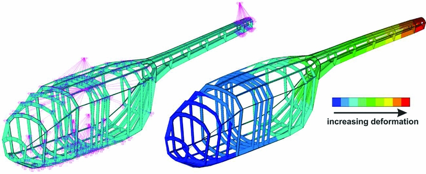
Figure 8. FEM analysis of the primary structure with the respect to major load cases (5).
In his paper (4), Lawrence described research into handling qualities conceptual design as a sub-discipline within the developing NASA multi-disciplinary, analysis/optimisation, conceptual design process model. He made the point that the “omission of flight dynamics modelling during conceptual design also defers flight dynamics, rotor response lags, and control authority considerations to later in the design process, which have led to problems during flight test”. Handling qualities optimisation impacts the design with trade-offs between, for example, the empennage size and flight control gains a good example. Lawrence suggested that the kinds of tools he was developing aim to bring “70 years of handling qualities engineering to the analysts’ fingertips”. However, as with all tools, the point was made that users must develop sufficient discipline expertise to be able to input data and interpret results intelligently.
Van der Velden's paper from Session 4 in the conference (18) also dealt with conceptual design using a probabilistic methodology, “to assess the cost and performance of system upgrades for a given Probabilistic Certificate of Correctness (PCC) metric”. He described an “analysis of alternatives (AoA)” for a fictitious upgrade to a UH-60L helicopter, with every user requirement and system attribute quantified as a probability density function, with a desired value and uncertainty. The PCC metric is the “probability that the actual physical aircraft will meet its benchmark acceptance tests based on virtual prototype behaviours”. A key phrase was the “quality of the analysis has to match the improvement sought”. Van der Velden argued that “there is a serious question of whether the AoA fairly compares different concepts when different technologies simulated by different analysis models are used”, because of the low VE fidelity used at these early stages. Also, Van der Velden noted that activities that occur later in the life-cycle, such as system development, airworthiness qualification and safety assessment, are often left out of the AoA, but could be brought in as part of the virtual prototyping.
One example presented used a Petri-Net framework to evaluate System Availability (Fig. 9). This discrete-event VE activity represented “the fact that for each mission-phase there is a different set of mission/safety critical systems. These mission critical systems are encoded through a fault-tree: each mission phase has its own unique event-tree modelled by tree indexes. Similarly, each mission phase will have its own safety critical system list (fault-tree). The Petri-Net input excel file has a table of information with mission phases, the mission and safety critical fault-trees, system/component reliabilities, etc.”.
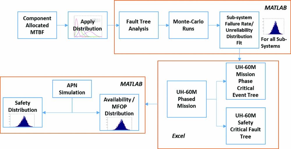
Figure 9. Process for reliability and safety analysis (18).
In his conclusion, Van der Velden recommended that “a PCC value of 0.7-0.8 is used during the AoA phase to balance the milestone risk with the AoA milestone effort. In later stages of the program the PCC needs to be steadily increased to values of around 0.9 in order to avoid program surprises”. This again chimes tunefully with Fig. 1.
The application of VE in conceptual design enables acquisition agencies and their research centres to develop better understandings of, for example, the mission effectiveness benefits and risks associated with stretched requirements and new technologies. But in his keynote paper (17) ‘A Model-Based Engineering Approach for Value-Based Acquisition (VBA)’, Schrage emphasised that VBA was about “capturing essential Life-Cycle Engineering elements as a ratio of System Effectiveness to Life-Cycle Cost, along with their weighting factors”. From the established need would then follow two major activities:
(1) “Use integrated Model Based Engineering (MBE) and Model Based Systems Engineering (MBSE) to develop baseline deterministic VPs for conducting trade-offs using Cost Capability Analysis (CCA) for decision-making at progressive milestones of the acquisition process,
(2) Transform a Deterministic Virtual Prototyping to a Stochastic Virtual Prototyping process to measure the level of modelling uncertainty and risk that exists and what confidence is required at the next major milestone”.
Schrage's presentation then focused on how RVE might aid the acquisition and design processes for the U.S. Army's Future Vertical Lift (FVL) program. Mature VE embodies trade studies that maximise the key metric – the ratio of system capability to life-cycle costs; the various symbols in Fig. 10 are defined in the paper, but include the key metrics for availability (α), capability (β) and dependability (δ, including a safety element) and cost (ϕ). Schrage emphasised the importance of all stakeholders participating in the system acquisition process and how VE can support and strengthen this engagement (Fig. 11). Schrage also reminded the audience of the objectives of VE – “to facilitate understanding, to aid decision making and examine ‘what-if’ scenarios and to explain, control and predict events”.
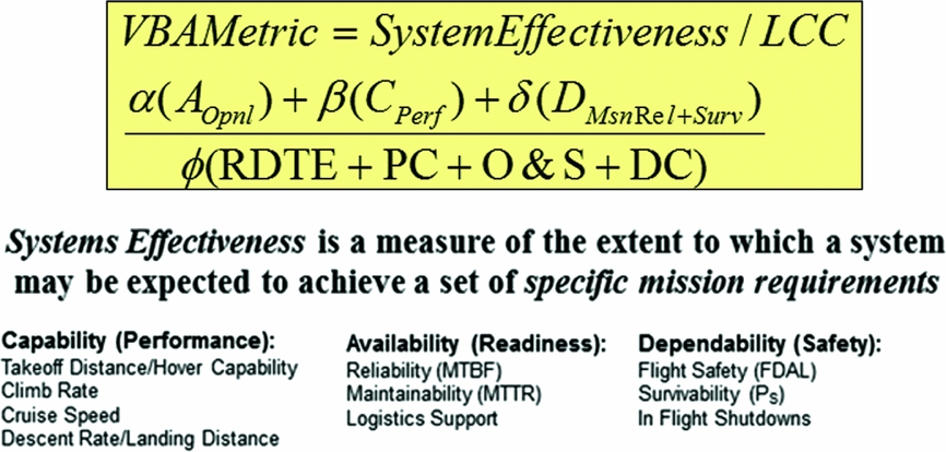
Figure 10. Schrage's VBA model for evaluating system effectiveness (17).
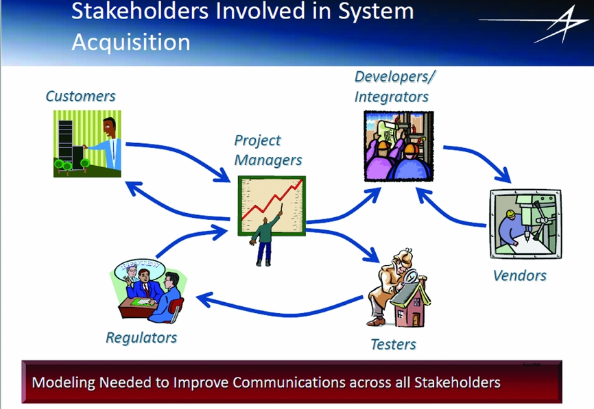
Figure 11. Key stakeholders must participate in system acquisition (17).
Session 2 mainly addressed how CFD featured as a VE tool. In the keynote presentation, Beaumier and Schwarz (6) described the DLR-ONERA vision for the future of CFD tools for rotorcraft. Beaumier stated that “current state-of-the-art software solves the Reynolds-Averaged Navier-Stokes (RANS) equations with the adjunction of more or less sophisticated turbulence models and are capable of simulating the aerodynamics of complete helicopters with good accuracy”. Furthermore, “the aerodynamic tools are now loosely coupled to Computational Structural Dynamics (CSD) codes, leading to a very good prediction of the main rotor blades aeroelastic response”. This capability has resulted from close collaboration between the two laboratories over many years, gradually refining tools like elsA (ONERA) as well as FLOWer and TAU (DLR) (Figs. 12 and 13). Despite excellent progress through this collaboration, the authors claimed that the further development of these VE tools is essential to reap the full benefits from application to rotorcraft engineering. Eight critical areas were discussed including efficiency when using 10k+computer cores, modelling multi-scale physics, relieving post-processing bottlenecks and, “one of the challenges is to incorporate the engineering knowledge of a human into numerical algorithms in terms of goal functions and constraints”. DLR and ONERA presented their roadmaps for CFD development, targeting massive parallel HPC platforms, higher order accuracy, increased reliability, improved physical modelling and open architecture software for coupling with other disciplines. Improving the validation process for VE/CFD use in certification is a major long-term goal for the laboratories.
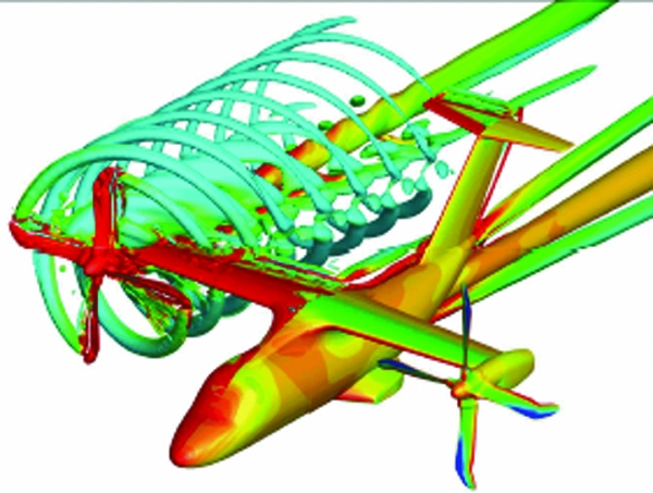
Figure 12. elsA calculation of a tilt-rotor full configuration (6).
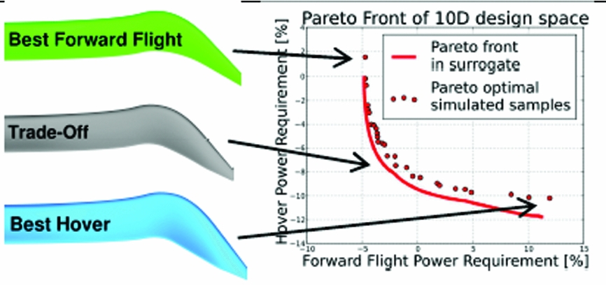
Figure 13. Rotor-optimisation based on CFD-solver FLOWer (6).
Barakos's presentation (7) focused on the coupling of flight mechanics simulations with CFD, with the component loads derived from the CFD solver and flight mechanics code predicting the helicopter states. A linear-quadratic regulator-based pilot model flew the simulation along a prescribed flight path, updated at very time step with the CFD-generated loads. Examples were presented of the kind of results output from the method, including application to helicopters landing on a ship's deck.
The helicopter-ship Dynamic Interface (DI) is not only one of the most challenging operational scenarios but also one of the most difficult to simulate. Owen presented highlights from a decade of research at Liverpool using simulation to create a virtual DI to explore such aspects as flight control design, pilot workload in the turbulent ship's airwake and the design of ships to enhance their helicopter-friendliness (9). Two core elements of the research have been the use of CFD to model the ship's airwake and the HELIFLIGHT-R motion-base simulator to explore handling and workload issues. The complexity of the CFD has increased over the years as more and more computing power became available. So has the fidelity of the simulation with pilots claiming that the bumpiness of the ride over the deck is significantly more realistic with an unsteady airwake. Figure 14 shows an example from a study into the features on the superstructure that give rise to problems for the pilot in starboard winds. In this case, the FLIGHTLAB helicopter model was flown along the approach and landing flight path to establish the areas where loadings, both steady and unsteady, would become difficult for a pilot to overcome.
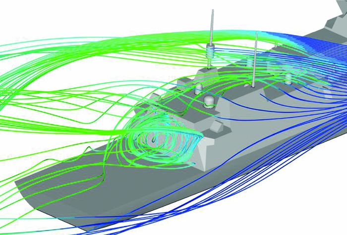
Figure 14. Virtual airdyne assessment of future frigate superstructure aerodynamics (9).
Simulating the helicopter-ship DI was also one of the examples given in the paper by White who described how Liverpool have been developing and running Continuing Professional Development (CPD) courses for industry based on Problem-Based Learning (PBL) (10). PBL was cited as an ideal approach for trainees to garner professional skills, knowledge and understanding through the use of VE tools, particularly real-time piloted simulations. The Liverpool work described in both these papers had strong engagement with Industry.
In her presentation (8), Smith challenged academia to understand better the user's needs when she said, “in many instances these innovative numerical modelling solutions languish at a low Technology Readiness Level (TRL) because of poor technology transfer and/or lack of proper uncertainty quantification of the solver”. The onerous costs of the verification and validation processes can also impede or even eliminate the ability to use innovative solutions. The presentation addressed some of the challenges at the interface of academic VE research and the needs of industry and government agencies, particularly in certification. Reinforcing the point made by Schrage and Van der Velden, Smith presented a process for uncertainty quantification and V&V for cyber-physical systems.
Papers in Sessions 3, 4 and 5 addressed VE in design and certification and included three papers on specific applications of VE. The first was presented by Beaumier (12) and described a 24-year long joint ONERA/DLR/Airbus programme, supported by numerical tools of varying complexity, to develop a new (Blue Edge TM) rotor system, achieving optimisation of aeroacoustic signature, structural dynamics and flight performance. The initial ERATO design achieved the acoustic signature goals (e.g. Figure 15) but led to reduced hover performance at high thrust.
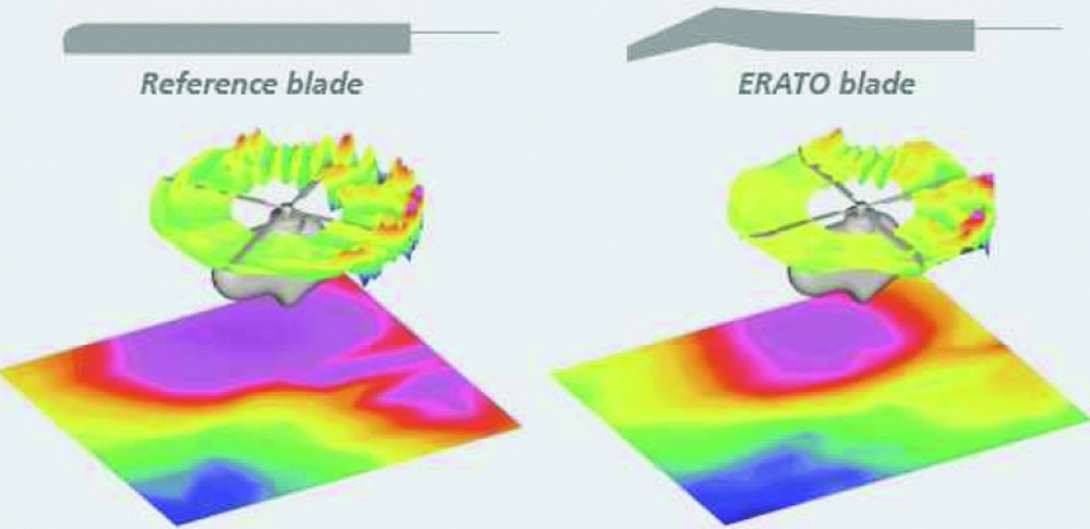
Figure 15. Acoustic results of DNW-LLF tests showing the ERATO rotor with significantly less BVI noise signature compared to the straight reference blade (12).
The ensuing Blue EdgeTM project contained 4 phases, with the first examining different variations on the ERATO blade using CFD, particularly the blade tip planform and aerofoil shape. During this evolution, it became apparent that aeroelastic tailoring would be essential for rotor stability and structural integrity. Both low- and high-‘order’ (relating to degree of complexity) VE models were used in the optimisation process to allow a very wide range of the design space to be explored. Phase 4 included a flight demonstration of the new rotor on a EC155 demonstrator. The success of the research and technology demonstration underpinned the maturity of the concept and a commitment was made to the first prototype of the Airbus H160 helicopter (Fig. 16). The presentation described the evolution of this technology from low- to high-Technology Readiness Levels (TRLs) and the importance of the collaboration between the research laboratories and industry, together with experimental validation through Mach-scaled models.
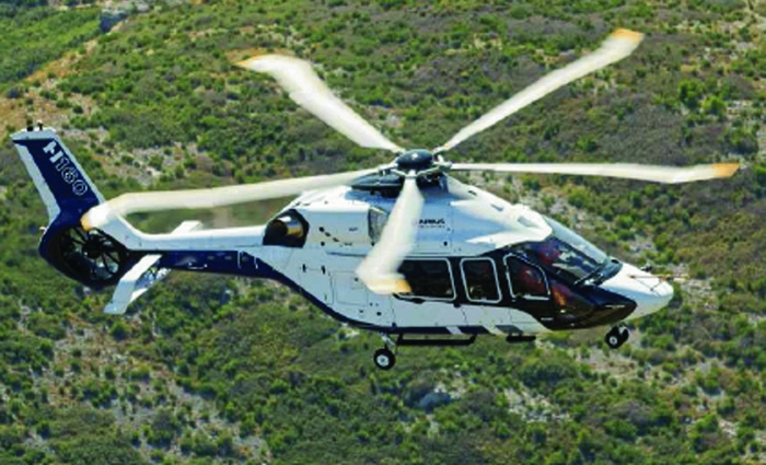
Figure 16. Flight testing trials of an Airbus Helicopters H160 prototype (12).
The second application example featured in Session 5 and concerned the modelling and simulation of particle upwash during helicopter landing, presented by Bakker of the Netherlands Aerospace Centre (21). Helicopter landings on unprepared terrain bring the risk of damage to critical helicopter components (e.g. engines, windscreen) and component wear from airborne foreign object debris. Aeromechanics simulations (using FLIGHTLAB) were conducted to establish trim conditions in steady descending flight (hence not including flare). The data was then input to a CFD computation (ENSOLV) of the rotor downwash and fuselage (Fig. 17). The particle (sand, grit and stones) trajectories are then computed using the Tecplot post-processing VE tool. A main conclusion of the study was that “typical landing approach paths always pass a region where it is likely that the helicopter will be hit by sand particles/stones” (Fig. 18). Bakker recommended the results be used as guidelines but any operational restrictions should be supported by flight test validation of the VE results.
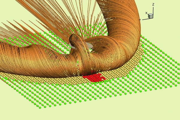
Figure 17. CFD prediction of the rotor wake – ground surface interaction (V=4kts) (21).
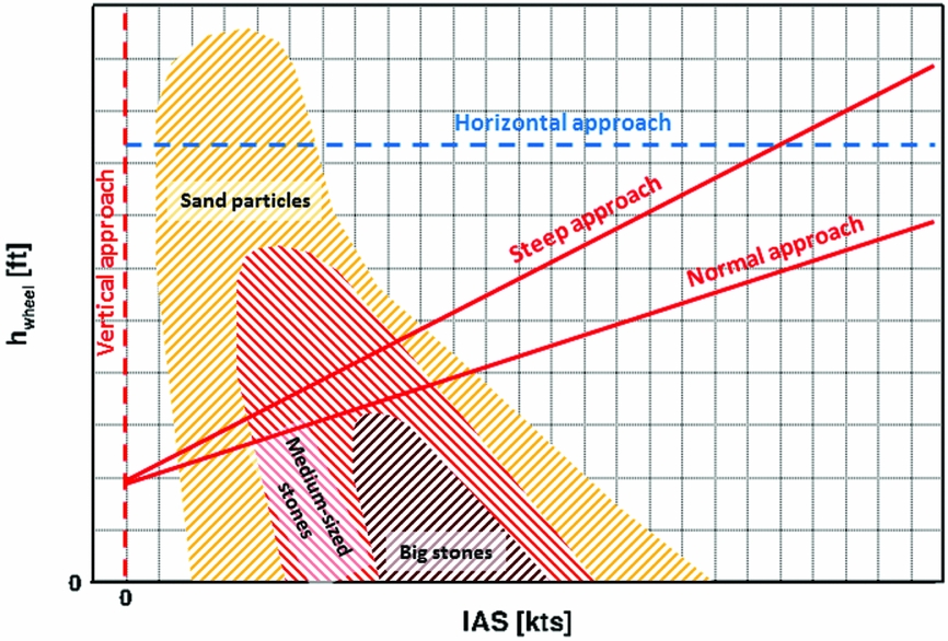
Figure 18. Chart depicting particles affected as a function of height and speed (21).
The third, completely different application, also presented in Session 5, concerned a mixed-reality simulation environment for a swarm of autonomous quadcopters, by Steup from the Otto-von-Guericke University (23). Steup described his attraction-repulsion based formation concept for a stable swarm. Combinations of sonar and IR sensors with inertial navigation systems and tracking cameras are used to control the swarm. The swarm control algorithms are developed virtually, in simulation, from which the conditions for a stable swarm are established. Steup explained that when applied to real aircraft, the swarm was unstable due to sensor information interference; this was the status of the project at the time of the conference and the team was investigating modelling the data interference to find a solution to the problem.
Real-time piloted simulation featured in several of the VE papers, e.g. in the Leonardo presentations already described and the heli-ship DI work at Liverpool. Two other papers in Session 3 also addressed this area. One by researchers at Politecnico di Milano (Polimi) was titled ‘Piloted Flight Simulation Using General-Purpose Multibody Dynamics’ and a status report on this project was presented by Masarati (15). The core of the system is the flight simulation module, which is based on the general-purpose multibody simulation package MBDyn, developed in Polimi. The modular structure of the system was described along with the unique problems faced in achieving numerical solutions in real time. The Polimi simulation facility is fixed-base but the second paper came from the DLR, and described the developments in motion cueing algorithms for the newly commissioned Air Vehicle Simulator (AVES, Fig. 19) (14), developed to support, among other applications, flight tests on the ACT-FHS in-flight simulator. The presentation by Jones described a genetic algorithm optimisation, “treating the parameters of the platform filters as unknowns, and using the motion software and hardware limits as constraints”. The optimisation process used flight test data and can evolve through the life-cycle of the simulator, “through changes to the operational use, vehicle configuration, and modifications to the system software and hardware limits”. Jones presented results showing a more than doubling of the motion travel range used following optimisation.
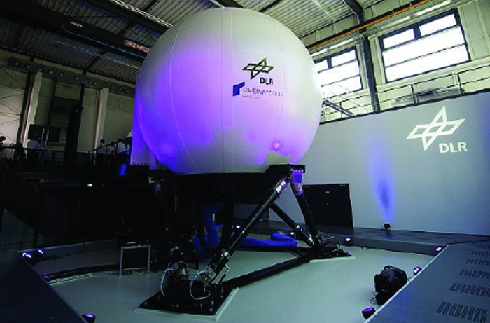
Figure 19. DLR AVES flight simulator (Jones).
Van Tooren, from the University of South Carolina, gave the keynote paper in Session 5 (20), on the theme of VE applied to “improving the performance of the fully composite aircraft by adopting and adapting many ideas that are available or under development to improve characteristics such as acquisition cost, weight, in-service cost and lead time, e.g. mixing, curving, printing, stirring, joining and monitoring of composites and their constituents”. The presentations also addressed the certification of non-conventional composite structures (e.g. when fibre layup angles change, or are steered, within a ply). The paper was unique in the subject area at the Conference but gave the delegates insight into the range of model scales involved in VE.
For example, most of these new technologies require in-depth material modelling. Gaining insight into mechanisms that control the various interfaces in a composite structure required modelling the molecular dynamics to predict the positions of atoms versus time. “These positions are derived from the forces exerted on an atom by the neighbouring atoms. To model molecules covalent bonds, valence angles and dihedral angles, springs can be used, whereas the intermolecular Van der Waals and Coulombic forces can be modelled by Lennard-Jones and point charge potentials respectively. Molecular simulations can be used to understand the solubility and diffusion processes occurring when a thermoplastic inserted into a resin transfer mould is interacting with the epoxy resin precursors. The simulations model the mechanisms which control the solubility and diffusion of thermoplastic polymers into epoxy resins” (e.g. Fig. 20).
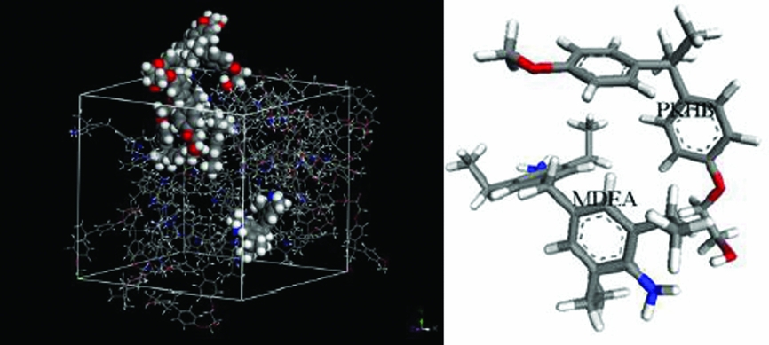
Figure 20. Example of microscale modelling inter-diffusion of thermoplastics and epoxy resin precursors (20).
The technique of curving fibre paths allows the tuning of load paths and strength from point to point in the structure, offering more design freedom than with isotropic-material-based design concepts. However, the increased design freedom comes with an increase in complexity of the material characterisation in a design environment. The current CAD/CAE generation is not yet able to support this amount of freedom. Van Tooren emphasised “The fundamental requirement to have displacements compatibility in a laminate is used to ‘steer’ load to certain areas by making them stiffer”. Fibre steering can be used to “create constant failure index structures with simultaneous stiffness and strength design to match load distribution and material system strength” (e.g. Fig. 21).
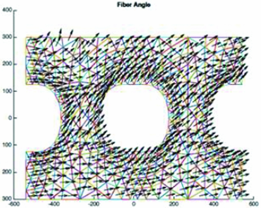
Figure 21. Example of a fibre angle field resulting from the optimisation within TopSteer (20).
Using VE in the design and manufacture of composite materials can help in a range of ways including the verification of ideas in conceptual design, to reveal similarities and differences in behaviour during repetitive design and to support multi-disciplinary optimisation by adding constraint and/or objective function compliance early in the design. Furthermore, as Van Tooren states in his keynote paper, the adoption of new multi-scale modelling in VE is strongly reinforcing. “Coupling of VE-based modelling applied to different length scales will help to understand the effects of changes on a microscopic scale on technology on a macroscale. VE supported application of the presented technologies on a macroscopic scale will help manufacturing engineers to apply the novelties in a controlled manner”.
Two VE product-oriented papers featured in the Conference, giving delegates an opportunity to see advances in commercially available VE tools. DuVal's presentation (FLIGHTLAB; A Suite of Rotorcraft VE Tools) (13) appeared in Session 3 and Van der Veldon's (Multi-Scale, Multi-Physics Systems Engineering) (24) in Session 6. DuVal also gave a more extensive description of the FLIGHTLAB tools during the technical tour. The range of Dassault Systemes/SIMULIA VE tools, supporting the whole life-cycle, was on display in the conference networking space. The Flightlab Development Environment (Fig. 22) allows uses to create, edit and analyse rotorcraft models and interact with modelling libraries, functions and a range of utilities including the real-time Pilotstation. In the paper, comparisons with experimental data were shown to support validation of the VE tools. Papers at the conference from Leonardo Helicopters, NLR and The University of Liverpool referenced the use of FLIGHTLAB in their research and development.
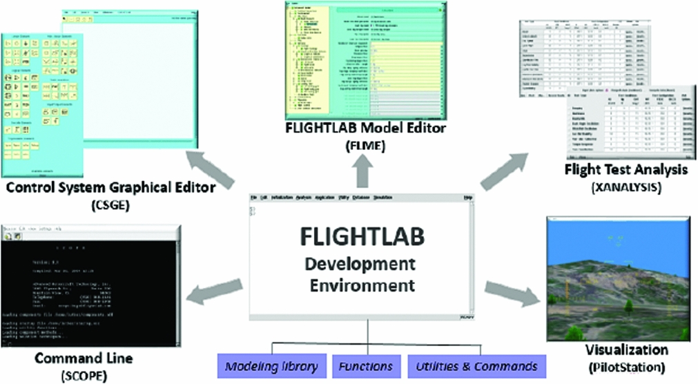
Figure 22. Summary of the FLIGHTLAB development environment (13).
4.0 CONCLUDING REMARKS
In his Introductory talk, the Conference Chair presented his vision for VE in the rotorcraft life-cycle, shown below. The bullet points are self-explanatory but the final piece of rhetoric suggested to the conference that VE offers a restoration of grace, imagination and artistry to the design process, through opportunities for discovery and insight, spurs to innovation, rapid-prototyping of ideas through ‘true’ optimisation and the integration of form, fit and function requirements with economic viability. Because of the investment needed to achieve mid-long terms goals, Padfield argued that achieving this vision requires strong leadership, starting at the highest level in organisations and woven into corporate cultures. It remains to be seen if this kind of leadership will shape the pathways in future rotorcraft acquisition.
A Vision for VE in the Rotorcraft Life-Cycle
• Let the VP become the centre of attention for synthesis, analysis and decision-making throughout the rotorcraft life-cycle
• Use common VPs and data throughout rotorcraft life-cycle phases
• Undertake VP Verification and Validation with regulatory-style enforcement throughout the life-cycle
• Create a VE approach to failure analysis, from the fractured pipe and the broken wire to the software coding error and the confused pilot
• Industry and Academia, working in partnership, focus on developing engineers with advanced VE skills and competencies for dealing with very complex systems
• Restore grace, imagination and artistry to the design process
The lead sponsor for the conference was Leonardo Helicopters, and Riccardo Bianco-Mengotti entertained the delegation in his pre-dinner talk about Leonardo da Vinci's use of VE over 500 years ago. During the conference, the importance of detail in the VPs was emphasised to achieve high fidelity. But Leonardo da Vinci showed us the other side of this when he said, “Go some distance away because then the world appears smaller and more of it can be taken in at a glance, and lack of harmony and proportion is more readily seen”. For sure, we need to see and understand the detail but we also need to see the big picture, for it is necessary for the world of customers and investors and in the boardroom, to understand why VE is so important.
A final word on the value of the collaborative effort involved in this conference. The six different partner organisations, the RAeS, AHS International, University of Liverpool, DGLR, 3AF and AIDAA, all worked to make this conference a success, through encouraging presenters and delegates to show up and evolve into a community that helped make the Conference a special occasion for all. The conference subject, Rotorcraft VE, is also very multi-disciplinary and spans the life-cycle, requiring special attention to assembling the various pieces that make the whole, in both these dimensions. The preparatory work of the lead engineers representing the various organisations, and subsequently as session chairs and panel discussion moderators, was critical to the success of the conference.
One of the actions taken away by these leaders was to consider the value of a working group to establish a common set of protocols and definitions of fidelity levels and how they fit into the use of VE throughout the life-cycle.
The conference papers and presentations will become available through a portal on the Royal Aeronautical Society's website, http://www.aerosociety.com/About-Us/Shop/Shop-Products?category=Proceedings .
APPENDIX – ROTORCRAFT VIRTUAL ENGINEERING PROGRAMME