1.0 INTRODUCTION
A modular aerospace system, where multiple applications of different criticality and certification assurance level are integrated on a shared computational resource, require analysable, deterministic and hard-real-time end-to-end communication for certification as well as safety purposes.
Systems of different criticality levels can have different timing requirements. For example a flight control system, an application of Design Assurance Level A (DAL A)(1), the highest level of criticality in aviation standards, has hard-real-time timing requirements where the timing margins are less than 10milliseconds(2), whereas a multimedia entertainment system, a DAL E application, does not have any such real-time requirements at all. The on-chip communication system should have the capability of prioritising critical applications to meet the hard-real-time requirements and eliminate the need for additional on-chip communication systems for soft-real-time requirements.
Communication between applications in an aerospace system is built upon the concept of sampling ports, where a fresh data packet overwrites an older data packet in a single packet buffer, and the receiving application can read it single or multiple times(Reference Alena, Ossenfort, Laws, Goforth and Figueroa3). Each subsystem may produce/consume single or multiple channel(s) once per computational cycle, where, each channel is assigned to specific parameters from IO devices or other subsystems. However, frequent communication between the applications and certain intellectual property cores (IPcores) (e.g. memory blocks or hardware-accelerators) can be expected and requires a larger communication bandwidth.
A faulty communication in the airborne system, as identified in Ref. (2), can be detected by the consumer application with a data validation technique, except for delivery of a message to a wrong recipient. Such an error can be caused by a faulty producer application or a faulty communication system, and some protection technique is essential to identify the source of incoming messages and guarantee the authenticity of received data packets.
The recent developments in on-chip communications are primarily focused on Network-on-Chip (NoC) architecture. The development is driven by general purpose computation needs and focused on efficient utilisation of network resources and best over-all performance (Reference Hesham, Rettkowski, Göhringer and Abd El Ghany4), and it often neglects the time-predictability aspects.
In this work, we present an on-chip network targeting application in aerospace systems-on-chip. We propose a mixed, priority-based and time-division-multiplexed (TDM) arbitration to support different bandwidth and latency requirements of mixed-criticality systems on the same network with additional data protection and isolation mechanism for safe and time-analysable end-to-end communication.
The specific contributions of this work include:
A real-time on-chip communication network architecture to accommodate different bandwidth and latency in the same network.
An arbitration mechanism to support different bandwidth and latency requirements with time-analysable end-to-end communication without packet loss.
A configurable isolation mechanism to prevent interference from erroneous transmission, and a hardware-level protection mechanism against unauthorised communication.
2.0 BACKGROUND AND RELATED WORK
2.1 Mixed criticality in aerospace system
In Integrated Modular Avionics (IMA)(5), several systems and subsystems of different criticality levels and functionalities are integrated on one hardware platform. Resource sharing and robust partitioning are the key concepts for such an implementation, where each partition is allocated a set of spatial resources and a mechanism in the platform that provides spatial segregation between them. The temporal isolation is established by allocating resources to the partitions at specific time slots and preventing access outside the time slot assigned to it. Hardware architecture of a typical IMA platform can consist of a set of computing processing modules that are grouped into clusters so that each group is connected to the same ARINC 664(Reference Fuchs, Schneele and Klein6) switch. Related systems and subsystems are implemented in the same group for low latency communication over the same switch(Reference Bieber, Boniol, Boyer, Noulard, Pagetti, Bieber, Boniol, Boyer, Noulard, Pagetti and Challenges7). Recent advancement in microprocessor technology provides a many-core processor, isolated from each other, where the IMA architecture can be implemented(Reference Perret, Maurere, Noulard, Pagetti, Sainrat and Triquet8) with an on-chip communication network for inter-system communication(Reference Moustapha Lo and Valot9,Reference Majumder, Dalsgaard Nielsen, Bak and La Cour-Harbo10) . Such single-core equivalent multi-core system, mutually isolated processors with dedicated resources, avails isolation between software running on separate processors and the requirement of isolation comes to the NoC for overall isolation in the system.
2.2 Network on Chip
The use of NoC in a real-time system imposes complex constraints in the overall design(Reference Sano, Soudris, Hübner and Diniz11).
Xpipes(Reference Bertozzi and Benini12) is a NoC where the network is tailored to meet the bandwidth requirements at its design stage. Such a system could be hard to implement as foreseeing the exact communication load is difficult to analyse and affects the scope of any future modification of the system. A circuit switching method is applied in SoCBUS(Reference Wiklund and Liu13) and a concept called a packet-connected circuit was introduced where a data packet is switched through a dynamic minimum route locking the circuit as it moves. This type of communication is effective where the traffic follows a fixed rule, but not effective where the data is not patterned like in an avionics system, where data sequence depends upon the relative state of the applications. In Ref. (Reference Pham, Park, Mau and Kim14), an alternative solution is proposed based on backtrack probing to avoid waiting for blocked channels to become available, seeking for alternative non-minimal routes. A synchronous circuit switching NoC is presented in Ref. (Reference Wolkotte, Smit, Rauwerda and Smit15), and a concept of spatial division multiplexing is introduced where the lane is divided to provide physical separation between data streams.
2.2.1 Priority
A connectionless packet-switching approach is demonstrated in Ref. (Reference Bolotin, Cidon, Ginosar and Kolodny16), where the routers work independently and a wormhole switching technique is typically used. The flows are prioritised based on some fixed manner, and the flow with the highest priority is given preference. The drawback of such a design is that packets with low priorities may be dropped or stalled for a long time and has a longer latency. In Ref. (Reference Lo, Lan, Yeh, Tsai, Hu and Chen17), the authors propose a low end-to-end latency with guaranteed service traffic. In Refs. (Reference Corrêa, Silva, Wagner and Carro18–Reference Diemer, Ernst and Kauschke20), the authors address the low priority packet block problem in connectionless NoC by introducing the concept of increasing priority over waiting time. In contrast, this work offers a mixed, best effort and guaranteed service traffic where flow with the highest priority is given preference by allocating more bandwidth, while flow with lower priority is given the minimum bandwidth allocated by the system designer to maintain worst-case time analysable communication.
2.2.2 Time Division Multiplexing
Time Division Multiplexing (TDM) is an arbitration scheme where a resource is shared between channels in the time domain; only one channel is given access to the resources to transmit for a fixed interval of time, called slots.
The concept of TDM is used in Refs. (Reference Millberg, Nilsson, Thid and Jantsch21) and (Reference Goossens, Dielissen and Radulescu22–Reference Stefan, Molnos and Goossens24), where the resource is allocated to channels based on time slots as an alternative to circuit switching. In Ref. (Reference Kasapaki, Schoeberl, Sorensen, Muller, Goossens and Sparso25), a globally asynchronous locally synchronous NoC has been illustrated for real-time application with mesosynchronous routers. The implementation uses a wormhole switching technique with TDM to prevent stall and deadlock and provides a solution in terms of no buffering, arbitration, real-time operation and no packet loss. However, the protection mechanism is not addressed in this work, which focusses on Worst-Case Execution Time (WCET) communication.
2.2.3 Related topologies
A star topology, where multiple ends are connected at a single point, can furnish a single cycle end-to-end flit transfer with effective control and monitoring capabilities at the cost of restricted communication between ends, where only one end can transmit at any given time. Such a topology offers an efficient solution for one-to-many and low latency communication and supports easy implementation of TDM or cyclic access to each end. As multiple ends are connected to a single point (one router), the packet routing is simple, and determinism is easy to achieve. Moreover, as all flits are routed through one single central router, the communication in the network can be easily monitored. Similarly, any subsystems can be isolated from the network without affecting other subsystems by restricting its access to transmit from the central router. However, the waiting time for transmission from a transmitter is linearly dependent upon the total number of transmitters in the network and can be long when a large number of communicating ends are connected.
In a tree topology, communication between the closer ends can be very fast as the flits need to hop through just one or a very few node(s). However, communication delay between two ends situated at two far ends of the network can have high latency as the communication gets bottlenecked at the top node.
3.0 ARCHITECTURE
In this work, a hybrid of star and tree topology has been considered, and this section explicitly addresses the architecture, the architectural benefits of the mixed-topology approach and microarchitecture of the network components.
3.1 Overall architecture
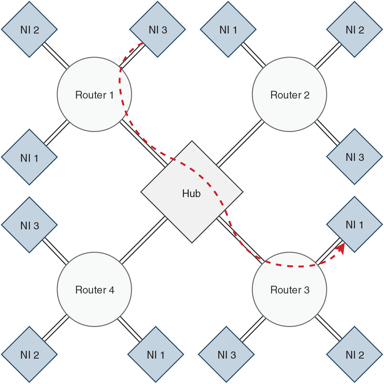
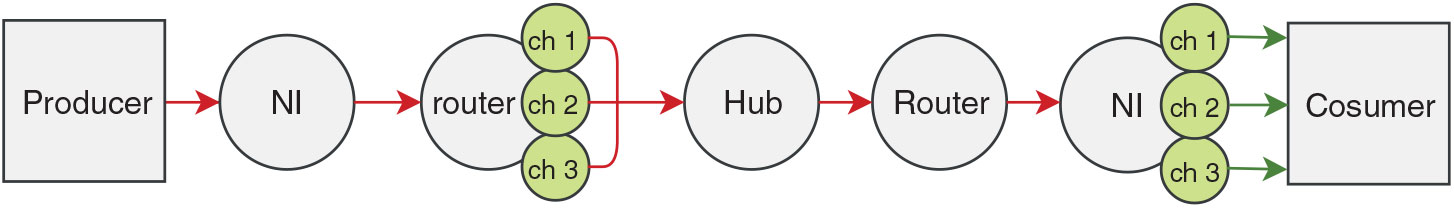
The network is built around a hub, interfaced with multiple routers in the network in a star topology and each router is attached to a single or multiple network-interfaces in a reverse fat-tree topology, as shown in Fig. 1. An end-to-end data packet propagation from a producer to a consumer through the network components is shown in Fig. 2. Under circumstances where one or multiple routers dysfunction, such an architecture allows the operation in the rest of the network to be invariant.

Figure 1. The proposed NoC architecture with 4 routers and 12 network-interfaces (NI). Communication flow between two NIs is highlighted.
Instead of conventional first in, first out (FIFO) buffers, dedicated sampling buffers are used to provide isolation to each channel. In cases of violation of transmitting agreement i.e. maximum allowed bandwidth, only the associated sampling buffer gets overwritten (dropping of old data packets of the violating channel), and the communication in the network and other data channels remain unaffected.
The phit size, physical channel width, is equal to the flit size in this network; thus, each flit can hop in a single cycle when access is provided.
3.2 Network interface
The NI in a NoC has a critical role in implementing end-to-end communication between two nodes. Figure 2 shows an example of data flow from a producer (Processor 1) to a consumer (Processor 2) via associated NIs. This section addresses the overall architecture and functionality of a NI in the proposed architecture.
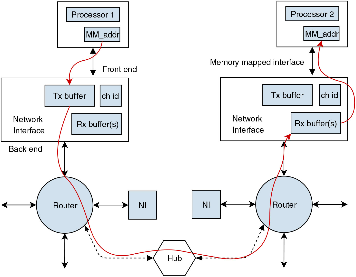
Figure 2. Block diagram showing end-to-end data packet flow.
Each NI has two ends, a front end and a back end, interfacing with the communicating end and the router, respectively. An NI is connected to the router with separate transmission and reception lines for simultaneous tx-rx operation and interfaced with the communicating end (i.e. a producer/consumer) with a standard memory-mapping technique. Additionally, each NI has a sampling transmission (Tx) buffer, a transmission channel index buffer and dedicated (Rx) sampling buffers for each receiving channel, as shown in Fig. 3.

Figure 3 Microarchitecture of the network-interface. The dashed lines represent configuration mode operations.
An NI can handle a fixed number of channels, and one or multiple NIs can be connected to a producer or consumer depending upon the requirement for the number of channels. To send a data packet to a destination NI, a producer writes the data in the transmission buffer with the channel id of the data packet with a standard memory writing method. Each channel has a configurable destination address stored in the NI that can be configured and re-configured by the producer before starting the network by writing in the control registers. The data packets are transmitted to the associated router. Each NI has a static identification number, and each NI in the network can be uniquely identified by a combination of associated router identification number and NI identification number, which is used as a unique destination address for transmission.
A fresh data packet written in the NI transmission buffer is sent to the connected router and concatenated with the destination address and channel id in its header. There could be application specific needs where the producer repeatedly sends the exact same data packets to the consumer; to identify the reception of a fresh data packet from the NI, at the router, a single bit signal line (NI to router) is toggled by the NI on every transmission. This mechanism has additional protective benefits that are explained later.
At the beginning of a reception (data flow from a router to NI), the associated router sets a single bit state signal to active, and the NI starts listening to the reception channel. On successful reception, the NI validates the received message by checking the source address in the header of the incoming data packet. Like a destination address, each NI has configurable expected-source addresses (address of the producers) for each receiving channel; The data packet is saved in the sampling buffer dedicated to the channel only if the source address matches with the expected-source-address, otherwise discarded.
3.3 Router
The routers in this network operate in a fixed routing scheme without any routing algorithm. Each router has a separate transmission and reception line to interface with the hub with two n-bit lines indicating access-request and access-grant status as shown in Fig. 4, where n is the number of NIs connected to the router.

Figure 4. Microarchitecture of the router in a three-NI configuration.
Each router has dedicated sampling buffers for each channel from each NI to guarantee isolation. The sampling buffers hold two flits (one data packet) with an 8-bit destination address.
Once a fresh data packet is received from an NI, the router raises a transmission request by setting the associated bit in the request line as high. The data packet received from the NIs are stored in their associated sampling buffers, unless the router gets transmission access. Once access is gained, the router transmits the data packet from the sampling buffer in three flits; i.e. one header flit, followed by two payload flits. The router adds a source address in the header flit next to the destination address.
There is no dedicated buffer for reception operation (hub to router); instead, the router packs the two payload flits with the source address and sends it to the destination NI (refer Fig. 8). Each router has a fixed and unique id so that a router NI id can be uniquely identified in the network.
3.4 Hub
The hub is the central and most critical component of the proposed architecture and controls arbitration. This section explains the microarchitecture of the hub.
The hub has separate transmission and reception channels for each router connected over a crossbar (X-bar), as shown in Fig. 5. The hub is memory-less and all the routing performed in the hub is atomic. Furthermore, the hub has separate n-bit request and access lines for each router connected, where n is the number of NIs connected to each router. The hub provides transmission access to each router for a specific NI when requested by setting the associated bit as high in the access line in a priority-TDM arbitration scheme, explained in the next section. The hub enables the Rx data line only from the router with transmission access. An erroneous transmission from a faulty router outside its access time gets discarded at the hub. Once the access is provided to a router, the router starts transmitting, and the hub checks for the destination router address in the header flit and activates the circuit to the destination router in the X-bar. The path is locked until the last flit of the packet propagates through it i.e. the second payload flit. Each transmission line to the routers has a single bit transmission-state line that is held as high by the hub during an active transmission to the destination router.
Figure 5. Microarchitecture of the hub in a four-router configuration: (a) transmission request lines from routers, (b) access lines to router, (c) input-data lines, (d) output-data lines and (e) active transmission lines.
If the hub reads a predefined destination address (e.g. 1111 1111, which is not a valid destination address in this four-router configuration), the hub broadcasts the packet to all the routers in the network.
4.0 ARBITRATION
In this section, we will discuss the conceptual aspects of the proposed arbitration and a generic way of implementation without concentrating on the specifics of the actual implementation in the NoC.
The goal of the arbitration is to accommodate a priority-based scheme with different band-width and different latency allocation to each communicating node, guarantying end-to-end time-deterministic communication without any packet loss. To accomplish this, a mixed concept of TDM and a priority-token-passing scheme is proposed.
Assume that a number of producers are connected to a central node that handles the arbitration by controlling the transmission line from each producer. Each producer can have different bandwidth and different latency requirements. However, the whole concept is based on the assumption that the size of the data packet is defined and identical for all the messages. Each producer is assigned a single or multiple slots in a TDM cycle based on its bandwidth requirements, and each slot in the TDM cycle has the same length as the transmission time of a data packet. To assure completion of undergoing data packet transmission i.e. if one data packet is unpacked in n flits and one flit transfer is m clock cycles long, then the slot length in the TDM cycle is  $n \times m$ clock cycles. A higher bandwidth requirement of a producer is addressed by assigning a higher number of TDM slots to the producer, where a low latency requirement is addressed by assigning multiple slots at multiple intervals in the TDM cycle, as shown in Fig. 6.
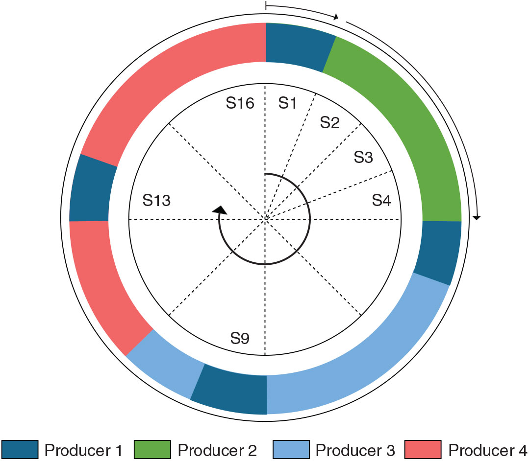
Figure 6. The figure shows allocated slots to different producers to meet latency and bandwidth requirements.
Figure 6 represents a hypothetical case where access is provided to four producers by a TDM cycle of 16 slots; Assume that producer 1 has the highest priority, low bandwidth and low latency requirements, producer 4 has the lowest priority and high bandwidth requirement, where producers 2 and 3 have moderate bandwidth requirement but the priority of producer 3 is higher than producer 2. The assumption taken into consideration is not random, and a relation to a practical scenario is drawn later in this section. The low latency requirement of producer 1 is accommodated by assigning multiple slots at multiple intervals to ensure that worst-possible waiting time to get access is small. The higher bandwidth requirement of producer 4 is fulfilled by assigning multiple slots. Producer 2 and 3 are assigned slots as per bandwidth requirements.
However, in a practical implementation, multiple slots assigned to each producer to meet its latency requirements are not always used, and such guaranteed service traffic is not efficient in terms of resource utilisation. For example, producer 1 only uses one of the multiple slots assigned to it to guarantee low latency transmission; additionally, as the TDM cycle of the network is often much shorter than the computational cycle of the communicating nodes, all of the producers do not transmit at every TDM cycle.
A priority-based token passing scheme, in addition to the TDM schedule, offers better resource utilisation where transmission access is given to the producers based on a concept of dynamic priority. The transmission access priority of a producer is determined by a prior knowledge of a priority assigned to each producer by the system designer and the slot the producer is competing for. All the fresh transmission requests are evaluated for the next slot, and the ongoing transmission is never interrupted to prevent unfinished or broken data packets at the producing or consuming end. Unserved accesses requests are re-considered for the subsequent slot unless it receives transmission access. A producer drops the access request when all the associated data packets are transmitted.
Each producer has the highest dynamic priority at the slot(s) initially assigned to it in the TDM cycle and definitely gets transmission access irrespective of the access requests from other high priority producers. The producer with the highest priority gets the transmission access when competing for a free/unused slot initially assigned to another producer.
This TDM-dynamic-priority scheme is elaborated in Fig. 7 with the same four producer scenarios considered earlier. The arrows show the transmission by each producer where the thin lines represent the time in the TDM cycle when the transmission request is received from each producer. At the beginning, producer 2 and 3 competes for slot 1 (which is allocated to producer 1 in the TDM cycle), and producer 3 gets the transmission access as it has the higher priority than producer 2 and no transmission request from producer 1; however, producer 2 gets the access of slot 2 and slot 3 as the dynamic priority of producer 2 is highest as these slots are allocated to it in the TDM cycle (refer to Fig. 6). Producer 2 completes the transmission and returns access at the end of slot 3, and producer 3 gets the access to the following slot. Transmission request from producer 1, with the highest priority, is received before completion of slot 4, and access is given for slot 5. The lowest priority producer 4 with the highest bandwidth requirements get the access at slot 8 when producer 3 finishes transmission. Producer 4 continues transmission unless finished at slot 15, and the network is idle at slot 16.
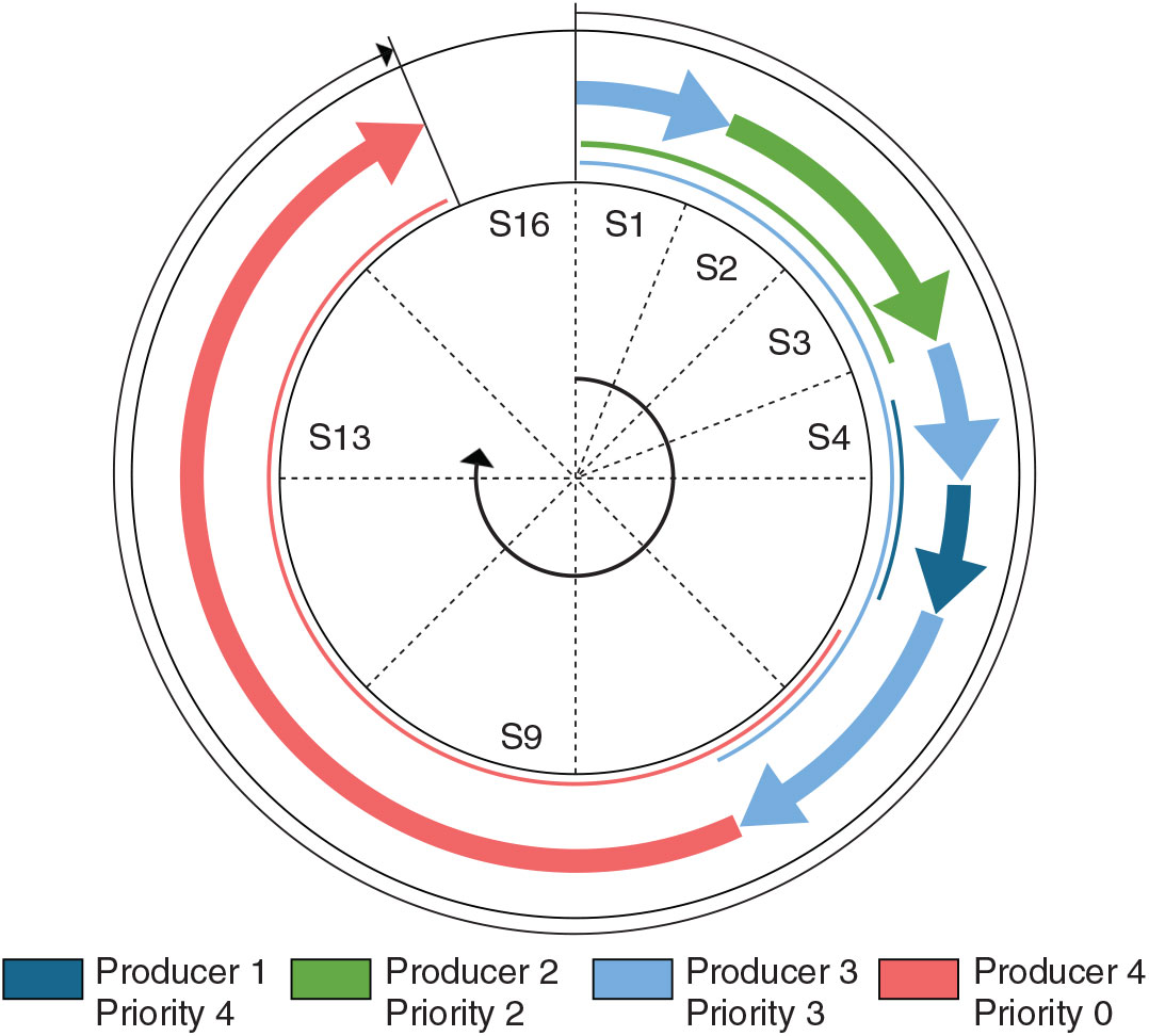
Figure 7. The figure shows transmission request and transmission access in the proposed priority-TDM cycle.
Such an arbitration can offer deterministic worst-case latency for all the producers and guarantee transmission of packets of different priorities. This is a mixture of best effort and guaranteed service where best effort is attempted when possible, but a guaranteed service is maintained under all possible conditions, even for the producers with lowest priority.
The effectiveness of the arbitration can be better understood by analysing in the context of flight control implementation, where signals with different functionalities and requirements can be categorised as discrete, sampling and streaming signals. Discrete signals are triggered on the occurrence of some event that are not frequent but needs low latency end-to-end transmission to meet hard-real-time constraints. Sampling data are regular and between subsystems or IO devices that are transmitted limited times (mostly once) per computational cycle. Streaming data, like log/data recorder or multimedia, has high bandwidth but lenient latency requirements.
The hypothetical example we considered earlier, in fact, represents the same framework where producer 1 represents discrete, producer 2 and 3 represent sampling and producer 4 represents streaming data transmission. When all the producers obey the transmission agreement, the operation takes place as explained. In case of a dysfunction in a high priority transmission, where the producer transmits more than the agreement, the arbitration guarantees transmission from low-priority producers, that is not achievable by a best effort only traffic.
5.0 IMPLEMENTATION
Microarchitectures of the network components and the arbitration have been explained in previous sections. This section explains the operation of the network.
5.1 Operation
The network must be configured before operation by configuring the destination and sources addresses in the NIs for each channel. This is done by writing in the destination address registers and expected-source address registers with a standard memory writing technique. There is no memory access mechanism like Direct memory access (DMA) in this network, and at the beginning of a transmission, the producer pushes a data packet to the associated NI by a standard writing method for sending it to a pre-configured destination. Recall, the NI’s interface with the communicating ends via a memory-mapped interface. As size of the data packets and the number of flits per data packet are predefined and fixed to avoid any skew, the need of a tail flit is obsolete in this architecture. The payload size is set to eight words, which should accommodate all data types used in control applications. The producer is responsible for evaluating the data size before transmission; if the data type is greater than the payload size, the data should be segmented and each segment is sent separately; however, a data type less than the payload size does not need any special treatment.
Once the writing process by the producer is complete, the data packet is transferred to the router in the next clock cycle. The data packet received from the NI at the router contains an 8-bit destination address, followed by a 2-bit channel id, followed by the payload as shown in Fig. 8. The flitisation and de-flitisation is done at the router on the received data from the NIs and the hub, respectively. The data packet from an NI is unpacked into flits, with a single header flit followed by the payload flits for transmission. The router adds a source address i.e. a concatenation of the router address, NI address and channel id in the header, which is later used for authentication. We have used a concept of the dynamic header where the size and information in the header changes as the packets flows through the network to reduce the amount of data flow, as shown in Fig. 8.
Figure 8. Packing and unpacking of the data packet and data packet header at different stages of flow – dst: 8-bit destination address; src: 8-bit source address; NI: 2-bit NI address; ch: 2-bits channel id.
The router sets the associated transmission request line as high, and the line is held high until all the flits from that specific NI are transmitted. The transmission access given to the routers are NI specific, and the router only transmits packets from the associated NI. This is how the notion of prioritised arbitration implemented in the hub is carried to the NIs.
The hub consumes a single flit from the X-bar for the router with the transmission access every clock cycle. A link is established between an input phit and an output phit based on the destination address carried by the first flit, and the associated transmission state line to the router is set to high in the same clock cycle. This path is maintained for at least the next two flits (two cycles) and until the hub revokes the access.
The input line from the hub to the router can consume a phit at every cycle. Three successive incoming flits are pipe-lined and re-structured for transmission through router-to-NI line that has a different phit size. The destination router de-flitise the flits with only destination channel id and the source address in the header before sending it to the destination NI.
At the consumer end, the channel of the received data packet is identified from the channel id in the header. Furthermore, the source id in the header is evaluated to check the authenticity of the producer. The packet is stored in the receiving channel buffer if the source address matches the expected source address, pre-configured in the NI.
5.2 Scheduling and latency analysis
The arbitration mechanism needs a static schedule before the network can operate, where slots for each channel should be configured as per latency and bandwidth requirements. This scheduling is done by the user and a separate process. A low latency requirement is fulfilled by assigning multiple distributed slots in the TDM cycle. This could be a complex process to strategically accommodate multiple slots in the TDM cycle as adding a new slot changes the TDM cycle time and affects the latency of other schedules. Moreover, the maximum number of slots in the TDM cycle is also limited due to physical limitation of resources. In this work, the maximum number of slots is fixed to 96.
A tool is developed that computes the schedule with an iterative method. The user needs to input the number of producers and bandwidth and latency requirements for each producer. The tools initiate by assigning the number of slots based on bandwidth requirements only, where higher requirement of bandwidth is accommodated by assigning more than one slot to the channel. Next, the tool sequentially picks the channel and inserts additional slots or removes slots assigned to the selected channel to meet latency requirements. Asserting or removing slots for one channel affects the schedule of other channels, and the tool iterates the process until the latency requirements are met for all the channels. The tool outputs the schedule and the total number of slots in the TDM-cycle. If the number of required cycles computed by the tool exceeds the physical limitation of the network, either the network needs to be reconfigured or the latency requirements should be more lenient, or number of channels can be reduced.
The end-to-end latency is dynamic and depends upon the number of communicating ends and load on the network. However, the worst-case latency only depends on the number of communicating nodes used in the network and fixed unless the configuration is modified. The worst-case latency can be computed by reversing the concept of scheduling, as:
 $$\begin{equation} \displaystyle L_{\rm channel} = \left(\left \lfloor {\frac{S_{\rm total}-1}{S_{\rm channel}}}\right \rfloor + 1 \right)\times t_{\rm slot} + 1\end{equation}$$
where, latency of a channel in clock cycles is  $L_{\rm channel}$,
  $S_{\rm channel}$ is the number of slots assigned to the channel,
  $S_{\rm total}$ is the total number of slots in the TDM-cycle and
  $t_{\rm slot}$ is the clock cycle per TDM-slot.
5.3 Protection and isolation
Data protection and established isolation are one of the primary concerns for application in mixed-criticality systems and a key contribution of this work. This section elaborates the isolation and protection aspect of the architecture in end-to-end packet flow.
An arbitrary transmission starts with a producer writing a data packet in the transmission buffer of the associated NI. There is no channel specific buffer for packet under transmission in the NI; however, the packet is transferred to the connected router atomically, establishing a temporal isolation between two successive packets from the same producer. Routers have dedicated sampling buffer to hold the packets under transmission, unless the transmission access is gained. The sampling buffers are isolated registers in the physical hardware, offering spatial isolation between each data packet. In a dysfunction condition where producer violates the transmission agreement and a new data packet is received at the router before the previous packet is transmitted, the old packet gets overwritten by the new packet, but data packets in other buffers remain unaffected.
The arbitration is implemented in the hub, and transmission access is provided in a deterministic schedule, guaranteeing access to each producer. The hub controls the transmission lines with a circuit switching mechanism, and only the router with transmission access is connected to the X-bar at any point of time, ensuring no-packet collision. The memoryless hub operations are atomic, establishing a temporal isolation. On the receiving end of the router, flits are packed and forwarded to the destination NIs. At the NI, each channel has its dedicated sampling buffer where the fresh data packet is saved for the consuming end to read. A dedicated sampling buffer provides a spatial isolation that prevents each feature from getting overwritten by a data packet from another channel before consumed by the consumer application when a transmission agreement is violated by a faulty application.
Communication between multiple systems is prone to erroneous transmission from a faulty application to a wrong recipient. Such a fault is hard to detect in the software if the faulty data is ranged within the expected data range at the consumer end.
In this network, the destination address is configured in the NI for each channel, and a dysfunction in the producing application cannot tamper with the destination. Additionally, the receiving NI has a pre-configured authorised source address for each channel. On reception of a data packet, the consumer NI checks for the source address before registering the message in the reading buffer. The source address is added by the router in the header during propagation, and the application has no control over it. Such a mechanism provides a two-step protection to prevent transmission to the wrong recipient.
Additionally, faults like frozen data are hard to detect where the producer system may transmit the same data to the consumer if there is no change in physical state. For example, in a cruise or hover condition, a flight control application can correctly send the same attitude data to a display application. A time stamp in DMA-based solutions significantly increases data flow and needs additional software to handle the timing data. In this work, the data packet transmission from the NI to the router is accompanied by a toggling signal that changes on every fresh transmission from the producer despite the content of the data packet; the router only registers the data from the NI when the toggling signal changes state, ensuring the transmission of only fresh data packets. The spatial and temporal isolation at different stages of data-packet flow in the proposed architecture is represented by a flow diagram in Figure 9.

Figure 9. Flow diagram showing temporal and spatial isolation in different stages. The arrows marked in red shows temporal isolation and the blocks and arrows marked in green show spatial isolation.
6.0 RESULTS AND DISCUSSION
6.1 Experimental setup
All the hardware is defined in Verilog HDL and synthesised on FPGA threads. In this work, we have used Xilinx ARTIX 7 and Intel Cyclone V SoC chip, although the hard embedded processor on the SoC was kept untouched. The board has a default 50MHz oscillator and two external oscillators of 80MHz and 100MHz and has been used for experimentation.
Each network component (NI, router and hub) are separate modules and defined as a Quartus custom/external IPCores, written in Verilog. Intel NIOS II soft processors are used as producers and consumers and connected with the NIs with an avalon memory-mapped interface. All the network components and the communication ends share the same global clock and reset signals. The components are inter-connected with Intel’s Quartus Platform designer tool. The connections between network components (NI-router and router-hub) are not visible to the platform designer tool and should be externally connected by editing the top module before synthesisation. Quartus Prime lite edition tool has been used for synthesis.
6.2 Performance
To evaluate the performance of the proposed network architecture, an example network has been configured with four routers and twelve NIs as shown in Fig. 1.
Table 1 shows worst-case latency analysis in different network configurations. Note that with the increase in the number of channels, the latency of each channel increases.
Table 1 Worst case latency analysis for different configurations with 8 bytes payload and 50MHz oscillator. All channels have equal priority

Table 2 Worst-case bandwidth of a channel in a 4-router, 36-channel configuration with different network clock frequencies. All channels have equal priority

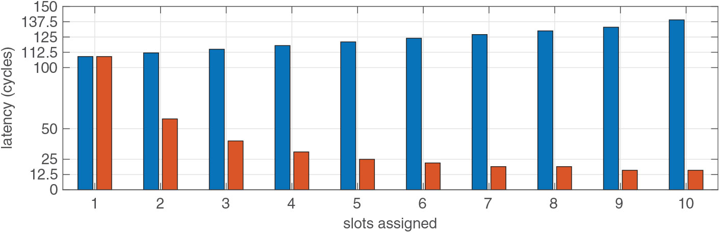
Table 1 shows worst-case latency analysis without any priority. However, if a channel has a lower latency requirement, meeting that requirement increases the worst-case latency of other channels in the network. Figure 10 shows the effect of lowering the latency of one channel in the rest of the channels in a 36-channel configuration.

Figure 10. The bars in red represent the latency of a channel with low latency requirements. The bars in blue show the latency of other channels. The horizontal axis shows the number of slots assigned to the low latency channel, and vertical axis shows the latency in cycles.
The bandwidth of the network depends upon the network clock frequency. The user can avail different oscillators depending on the bandwidth requirement. Table 2 shows the minimum bandwidth for a 4-router, 36-channel configuration with different clock frequencies.
7.0 CONCLUSION
We have proposed a network-on-chip architecture for the intended application in real-time mixed-criticality systems, like integrated modular avionics platforms, which has some unique benefits: real-time end-to-end communication with isolation between data packets under transmission, different latency and bandwidth allocation in the same network and protection mechanism for authentic transmission that plays a critical role in safety-critical applications. Additionally, the concept of combined priority and TDM arbitration has been extended for better utilisation of the network resources to allow more low priority applications to utilise the network while maintaining determinism worst-case latency for all the applications. However, the topology is subject to a linear extension in worst-case latency with expansion.
IMA is new technology with evolving guidance and requirements. The use of multi-core processors is new in today’s avionics, and the exact requirements of inter-core and inter-application communication is still under investigation (2). The performance of the proposed architecture, in terms of bandwidth and latency, is more than adequate to meet the requirements of conventional on-board applications. The fixed resources for the network components set a limit to the performance capabilities of the proposed architecture and increased bandwidth or low latency demand in one channel affects the other channels. However, the worst-case performance is deterministic and analysable for the system designer, and no anomaly occurs during run-time. The hub in this architecture is the most critical component and could be a single point of failure. However, the applications do not have any effect on the hub, and the hub is only susceptible to hardware failures. A redundant implementation of the hub or the entire network can be considered for enhancing reliability measures.
The work was mainly focused on meeting the requirements of safety-critical aerospace applications, and the scope of efficient resource utilisation was not considered. Furthermore, the isolation mechanism degrades the efficiency of resource utilisation as compared to general purpose communication. Further extension of this research to support inter-chip communication and scalability can be addressed in future research. We have implemented a lighter version of the proposed network in an asymmetric multiprocessor architecture to demonstrate improvements in the reliability of on-board computations in small airborne platforms(Reference Majumder, Dalsgaard Nielsen, Bak and La Cour-Harbo10).
ACKNOWLEDGEMENT
The authors would like to thank John-Josef Leth from Aalborg University and Martin Schoeberl and Jens Sparsø from Technical University of Denmark for their insightful comments and helpful discussion.