


NOMENCLATURE
- a
length in the X direction
- b
length in the Y direction
- E i
Young’s modulus of impactor
- E m
Young’s modulus of matrix
- E 0
reference value of Young’s modulus of panel
- E 11
longitudinal effective Young’s modulus
-
 $E_{{11}}^{{{\rm CN}}} $
longitudinal carbon nanotube Young’s modulus
- E 22
transverse effective Young’s modulus
-
$$E_{{22}}^{{{\rm CN}}} $$
transverse carbon nanotube Young’s modulus
-
$E_{{22}}^{{\rm s}} $
transverse Young’s moduli of the surface the panel
-
$$\overline{F} (X,Y)$$
stress function
- G m
shear moduli of matrix
- G 12
shear moduli of the orthotropic layer
-
$G_{{12}}^{{{\rm CN}}} $
in-plane shear modulus of carbon nanotube
- h
total thickness of panel
- h c
thickness of core
- h f
thickness of face sheet
- K c
contact stiffness
- m i
mass of impactor
-
$\bar{M}^{T} $
moment
-
$\bar{M}_{x} ,\,\bar{M}_{y} $
bending moments
-
$\bar{N}^{T} $
force
-
$\bar{N}_{x} ,\,\bar{N}_{y} ,\,\bar{N}_{{xy}} $
stress resultants
- P c
the overall contact force
-
$P_{{\max }} $
maximum contact force
-
$\bar{P}^{T} $
higher order moment
-
$\bar{P}_{x} ,\,\bar{P}_{y} $
higher order moments
-
$\bar{Q}_{{ij}} $
transformed elastic constants
- R
curvature radius of panel
- R c
radius of the panel
- R i
radius of impactor
- T 0
reference temperature
-
$\bar{U}$
panel displacement in the direction of X
- V 0
initial velocity of impactor
-
$\bar{V}$
panel displacement in the direction of Y
- V CN
volume fraction of carbon nanotube
- V m
volume fraction of matrix
-
$\bar{W}$
panel displacement in the direction of Z
- X, Y, and Z
directions of co-ordinate system


Greek symbol
- αm
thermal expansion of matrix
- α11
effective longitudinal thermal expansion coefficient
-
${\rm \ralpha }_{{{\rm 11}}}^{{{\rm CN}}} $
longitudinal thermal expansion coefficient of carbon nanotube
- α22
effective transverse thermal expansion coefficient
-
${\rm \ralpha }_{{{\rm 22}}}^{{{\rm CN}}} $
transverse thermal expansion coefficient of carbon nanotube
- δ(t)
local contact indentation
-
${\rm \rdelta }_{{\max }} $
maximum local indentation
- ΔT
temperature change
- η i
efficiency parameters of carbon nanotube
- ν i
Poisson’s ratios of impactor
- ν12, ν21
Poisson’s ratios of the orthotropic layer
- ρCN
density of carbon nanotube
- ρm
density of matrix
- ρ0
reference value of panel density
-
${\rm \bar{\rpsi }}_{x} $
the mid-plane rotation of normal about the Y axis
-
${\rm \bar{\rpsi }}_{y} $
the mid-plane rotation of normal about the X-axis


1.0 INTRODUCTION
Due to their outstanding mechanical, thermal and electrical properties( Reference Coleman, Khan, Blau and Gun’ko 1 – Reference Haider, Majumdar, Angeloni and Reifsnider 3 ), carbon nanotubes (CNTs) are regarded as one the most favourable reinforcement materials for high-strength and light-weighted polymer composites. Dissimilar to carbon fibre-reinforced composites, only a low percentage of CNTs (2–5 wt%)( Reference Han and Elliott 4 , Reference Bonnet, Sireude, Garnier and Chauvet 5 ) are allowed in CNT-reinforced composites (CNTRCs) because more volume fraction beyond a certain limit will worsen their mechanical properties( Reference Meguid and Sun 6 ). Hence, the idea of functionally graded (FG) materials was employed in order to optimally utilise the CNT reinforcement effect. Shen( Reference Shen 7 ) first applied the concept of FG materials to nanocomposites and investigated the non-linear bending behaviour of CNTRC plates and observed that the plate load-bending moment curves significantly improved due to the FG distribution of CNTs through the thickness. Also, Kwon et al.( Reference Kwon, Bradbury and Leparoux 8 ) proposed a powder metallurgy route for fabricating FG CNT-reinforced aluminium (Al) matrix composite which completely supports the concept of FG nanocomposites. Furthermore, Shen and Xiang( Reference Shen and Xiang 9 ) investigated non-linear temperature-dependent large amplitude vibration behaviour of FG-CNTRC cylindrical panels resting on elastic foundations. They found that non-linear to linear frequency ratios of CNTRC panels with intermediate volume fraction of CNTs is not necessarily intermediate.
A thick but lightweight material as core, embedded in two thin but stiff materials such as face sheets, forms a structure with high bending stiffness and low overall density, which is called the sandwich structure. Sandwich panels are extensively used in aeronautical and automotive applications as well as civil infrastructure, such as highway bridges( Reference Davalos, Qiao, Frank Xu, Robinson and Barth 10 ). Especially, under impact loading, sandwich panels are susceptible to face sheet/core debonding due to the difference in stiffness properties between core and face sheets( Reference Apetre, Sankar and Ambur 11 ). The purpose of this work is to examine the behaviour of CNTRC sandwich panels subjected to low-velocity impact. FG materials usually consist of ceramic and metal phases with varying mechanical properties through the thickness. For further information on FG materials one can refer to Ref. Reference Miyamoto, Kaysser, Rabin and Kawasaki12. Utilising an FG core in sandwich panels expressively can reduce the face sheet–core interfacial shear stresses and so the possibility of face sheet/core debonding( Reference Venkataraman and Sankar 13 ).
Fibre–metal laminate (FML) is an advanced hybrid composite material consisting of some thin metal layers bonded with composite material layers. FMLs allow metal benefits such as ductility, damage and impact tolerances to be combined with good features of composite materials such as high specific stiffness and strength, good fatigue and corrosion resistance( Reference Vlot and Gunnink 14 – Reference Vlot and Krull 17 ). The combination of metal and composite characteristics in one material makes FMLs a powerful applicant material for new generation and high-capacity aircraft fuselage skin structures. FMLs also can be used as face sheets in sandwich panels. Tan and Akil( Reference Tan and Akil 18 ) explored the impact response of sandwich composite structure with polypropylene honeycomb core and FML face sheet. They found that with increasing impact energy, the maximum impact load increases up to a threshold value and then plateaus while the energy absorption will increase continuously. Similar to FML, CNTRCs can be used to form a CNT–metal laminate (CNTML) composite which consist of thin metal layers such as Al, bonded with CNTRC layers.
Low-velocity impact is one of the most crucial loadings that composite structures experience during their service life, especially for aerospace composite structures( Reference Aktaş, Atas, İçten and Karakuzu 19 , Reference Salami 20 ). Wang et al.( Reference Wang, Waas and Wang 21 ) studied the low-velocity impact response of foam-core sandwich panels using experimental and numerical approaches. They also explored the effects of impact variables and sandwich panel configuration parameters on the impact behaviour. Jam and Kiani( Reference Jam and Kiani 22 ) used Timoshenko beam theory to analyse the influences of thermal environment, CNT volume fraction, distribution of CNTs, initial velocity and mass of impactor on low-velocity impact response of FG-CNTRC composite beams. Wang et al.( Reference Wang, Xu and Qiao 23 ) analysed the temperature-dependent low-velocity impact response of single-layer FG-CNTRC as well as sandwich composite plates and examined the effect of various impact and environmental parameters. The low-velocity impact response of Al foam sandwich structures with fibre-reinforced thermoplastic and FML face sheets was modelled using a simple energy-balance model by Kiratisaevee and Cantwell( Reference Kiratisaevee 24 ). Using experimental and numerical methods, Meo et al.( Reference Meo, Vignjevic and Marengo 25 ) studied the low-velocity impact response of the composite sandwich panels at five various energy levels. They found that at relatively low impact-energy levels, notable internal damage may occur which could reduce the residual strength of panel significantly.
To the best of the readers’ knowledge, and as the literature survey accepts, there is no study neither on the low-velocity impact response of sandwich nor CNTML and FG-CNTRC cylindrical panels. In this study, the non-linear temperature-dependent low-velocity impact response of nanotube-reinforced composite cylindrical panel-type structures is studied. Three types of cylindrical panel configurations (i.e. single-layer, CNTML and sandwich cylindrical panels) are considered in which CNTs are either uniformly distributed (UD) or FG through the thickness direction. In the sandwich configuration, two types of core (i.e. homogenous and FG) are considered embedded in two CNTML face sheets. Micromechanical models are used to estimate the material properties. A higher-order shear deformation theory( Reference Reddy 26 ) with a von Kármán-type of kinematic non-linearity( Reference Huishen 27 ) and thermal effects is used to form the equations of motion. Material properties of all types of configurations are assumed to be temperature dependent. Two types of boundary conditions (i.e. movable and immovable) are used for all edges of cylindrical panel. The numerical results illustrate the non-linear low-velocity impact response of different kinds of composite cylindrical panels under various sets of environmental conditions.
2.0 NON-LINEAR DYNAMICS OF CNTRC CYLINDRICAL PANELS
The cylindrical panel studied in this paper is composed of two CNTML face sheets and a homogenous or FG core. As shown in Fig. 1, the radius of curvature, total thickness of panel, length in the X and Y directions are designated as R, h, a and b, respectively. The thickness of each face sheets and core is h
f and h
c, respectively. The nanotube reinforcement used in CNTML of face sheets are either UD or FG. The panel is subjected to low-velocity impact in various thermal conditions. The origin of co-ordinate system is at the corner of the panel on the mid-plane (see Fig. 1). Parallel to the right-hand set of axes (X, Y, Z), in which X and Y are in the axial and circumferential directions of the panel and Z is in the direction of the inward normal to the middle surface, panel displacements are designated as
 $\overline{U} $
,
$\overline{U} $
,
 $\overline{V} $
and
$\overline{V} $
and
 $\overline{W} $
. The mid-plane rotations of normal about the Y and X axes are labelled as
$\overline{W} $
. The mid-plane rotations of normal about the Y and X axes are labelled as
 $\overline{\Psi } _{x} $
and
$\overline{\Psi } _{x} $
and
 $\overline{\Psi } _{y} $
, respectively. The stress resultants are given as
$\overline{\Psi } _{y} $
, respectively. The stress resultants are given as
 $$\overline{N} _{x} {\equals}\overline{F} _{{,YY}} $$
,
$$\overline{N} _{x} {\equals}\overline{F} _{{,YY}} $$
,
 $\overline{N} _{y} {\equals}\overline{F} _{{,XX}} $
and
$\overline{N} _{y} {\equals}\overline{F} _{{,XX}} $
and
 $\overline{N} _{{xy}} {\equals}{\minus}\overline{F} _{{,XY}} $
, where
$\overline{N} _{{xy}} {\equals}{\minus}\overline{F} _{{,XY}} $
, where
 $\overline{F} (X,Y)$
is the stress function in which partial differential with respect to the corresponding co-ordinates is denoted as comma. It should be noted that all calculations for layers will be carried out using this co-ordinate system.
$\overline{F} (X,Y)$
is the stress function in which partial differential with respect to the corresponding co-ordinates is denoted as comma. It should be noted that all calculations for layers will be carried out using this co-ordinate system.
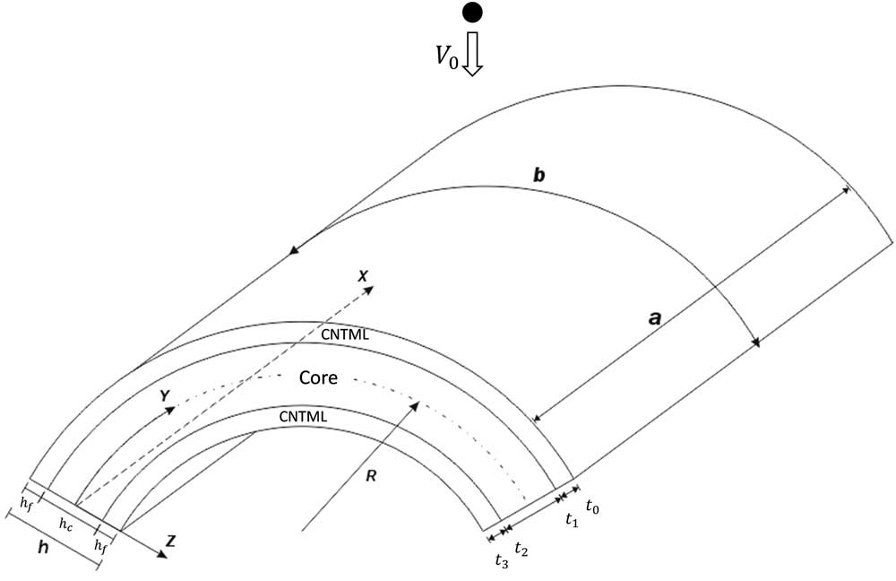
Figure 1 Co-ordinate system and geometry of cylindrical panel subjected to low-velocity impact.
Reddy and Liu(
Reference Reddy and Liu
28
) modified Sanders shell theory and developed a higher-order shear deformation shell theory. In this theory, the transverse shear strains are assumed to be parabolically distributed across the shell thickness and the number of independent unknowns (
 $\overline{U} $
,
$\overline{U} $
,
 $\overline{V} $
,
$\overline{V} $
,
 $\overline{W} $
,
$\overline{W} $
,
 $\overline{\Psi } _{x} $
and
$\overline{\Psi } _{x} $
and
 $\overline{\Psi } _{y} $
) is the same as in the first-order shear deformation theory; however, there is no need for the correction factor. The motion equations of cylindrical panel can be expressed in terms of a transverse displacement
$\overline{\Psi } _{y} $
) is the same as in the first-order shear deformation theory; however, there is no need for the correction factor. The motion equations of cylindrical panel can be expressed in terms of a transverse displacement
 $\overline{W} $
, two rotations
$\overline{W} $
, two rotations
 $\overline{\Psi } _{x} $
and
$\overline{\Psi } _{x} $
and
 $\overline{\Psi } _{y} $
, and a stress function
$\overline{\Psi } _{y} $
, and a stress function
 $\overline{F} $
, based on Reddy’s higher-order shear deformation theory with a von Kármán-type of kinematic non-linearity and thermal effects(
Reference Shen and Xiang
9
), as follows:
$\overline{F} $
, based on Reddy’s higher-order shear deformation theory with a von Kármán-type of kinematic non-linearity and thermal effects(
Reference Shen and Xiang
9
), as follows:
 $$\eqalignno{ & \widetilde{L}_{{11}} \left( {\overline{W} } \right){\minus}\widetilde{L}_{{12}} \left( {\overline{\Psi } _{x} } \right){\minus}\widetilde{L}_{{13}} \left( {\overline{\Psi } _{y} } \right){\plus}\widetilde{L}_{{14}} \left( {\overline{F} } \right){\minus}\widetilde{L}_{{15}} \left( {\overline{N} ^{T} } \right){\minus}\widetilde{L}_{{16}} \left( {\overline{M} ^{T} } \right){\minus}{1 \over R}\overline{F} ,_{{XX}} \cr & \quad \quad {\equals}\widetilde{L}\left( {\overline{W} ,\overline{F} } \right){\plus}\widetilde{L}_{{17}} \left( {\mathop{{\overline{W} }}\limits^{{..}} } \right){\minus}\sleft( {\widetilde{I}_{5} {{\partial \mathop{{\overline{\Psi } }}\limits^{{..}}} _{x} \over {\partial X}}{\plus}\widetilde{I}_{5}^{\hskip1.5pt'} {{\partial \mathop{{\overline{\Psi } }}\limits^{{..}} }_{y} \over {\partial Y}}} \right){\plus}q $$
 $$\eqalignno{ & \widetilde{L}_{{21}} \left( {\overline{F} } \right){\plus}\widetilde{L}_{{22}} \left( {\overline{\Psi } _{x} } \right){\plus}\widetilde{L}_{{23}} \left( {\overline{\Psi } _{y} } \right){\minus}\widetilde{L}_{{24}} \left( {\overline{W} } \right){\minus}\widetilde{L}_{{25}} \left( {\overline{N} ^{T} } \right){\plus}{1 \over R} \overline{W} ,_{{XX}} {\equals}{\minus}{1 \over 2}\widetilde{L}\left( {\overline{W} ,\overline{W} } \right) $$
 $$\eqalignno{ & \widetilde{L}_{{31}} \left( {\overline{W} } \right){\plus}\widetilde{L}_{{32}} \left( {\overline{\Psi } _{x} } \right){\minus}\widetilde{L}_{{33}} \left( {\overline{\Psi } _{y} } \right){\plus}\widetilde{L}_{{34}} \left( {\overline{F} } \right){\minus}\widetilde{L}_{{35}} \left( {\overline{N} ^{T} } \right){\minus}\widetilde{L}_{{36}} \left( {\overline{S} ^{T} } \right) {\equals}\widehat{I}_{5} {{\partial \mathop{{\overline{W} }}\limits^{{..}} } \over {\partial X}}{\minus}\widehat{I}_{3} {\mathop{{\overline{\Psi } }}\limits^{{..}}}_{x} $$
 $$\eqalignno{ & \widetilde{L}_{{41}} \left( {\overline{W} } \right){\minus}\widetilde{L}_{{42}} \left( {\overline{\Psi } _{x} } \right){\plus}\widetilde{L}_{{43}} \left( {\overline{\Psi } _{y} } \right){\plus}\widetilde{L}_{{44}} \left( {\overline{F} } \right){\minus}\widetilde{L}_{{45}} \left( {\overline{N} ^{T} } \right){\minus}\widetilde{L}_{{46}} \left( {\overline{S} ^{T} } \right) {\equals}\widehat{I}_{5}^{\hskip1.5pt'} {{\partial \mathop{{\overline{W} }}\limits^{{..}} } \over {\partial Y}}{\minus} \widehat{I}_{3}^{\hskip1.5pt'} {\mathop{{\overline{\Psi } }}\limits^{{..}}}_{y} $$
in which
 $$\widetilde{L}( ){\equals}{{\partial ^{2} } \over {\partial X^{2} }}{{\partial ^{2} } \over {\partial Y^{2} }}{\minus}2{{\partial ^{2} } \over {\partial X\partial Y}}{{\partial ^{2} } \over {\partial Y\partial X}}{\plus}{{\partial ^{2} } \over {\partial Y^{2} }}{{\partial ^{2} } \over {\partial X^{2} }}$$
 $$\widetilde{L}_{{17}} ( ){\equals}{\minus}I_{1} {\minus}\left( {\widetilde{I}_{7} {{\partial ^{2} } \over {\partial X^{2} }}{\plus}\widetilde{I}_{7}^{\hskip1.5pt'} {{\partial ^{2} } \over {\partial Y^{2} }}} \right)$$
and the other linear operators
 $\widetilde{L}_{{ij}} ( )$
are given in Refs Reference Shen29,Reference Shen30. I
j
,
$\widetilde{L}_{{ij}} ( )$
are given in Refs Reference Shen29,Reference Shen30. I
j
,
 $\widehat{I}_{j} $
and
$\widehat{I}_{j} $
and
 $\widetilde{I}_{j} $
are given in Equation (19) below. The von Kármán type geometric non-linearity is embedded in terms of
$\widetilde{I}_{j} $
are given in Equation (19) below. The von Kármán type geometric non-linearity is embedded in terms of
 $\widetilde{L}( )$
in Equations (1) and (2). In Equations (1)–(4), differentiation with respect to time is denoted with superposed dots. Forces
$\widetilde{L}( )$
in Equations (1) and (2). In Equations (1)–(4), differentiation with respect to time is denoted with superposed dots. Forces
 $$\overline{N} ^{T} $$
, moments
$$\overline{N} ^{T} $$
, moments
 $\overline{M} ^{T} $
and higher order moments
$\overline{M} ^{T} $
and higher order moments
 $\overline{P} ^{T} $
caused by elevated temperature are given by
$\overline{P} ^{T} $
caused by elevated temperature are given by
 $$\left[ {\matrix{ {\overline{N} _{x}^{T} } & {\overline{M} _{x}^{T} } & {\overline{P} _{x}^{T} } \cr {\overline{N} _{y}^{T} } & {\overline{M} _{y}^{T} } & {\overline{P} _{y}^{T} } \cr {\overline{N} _{{xy}}^{T} } & {\overline{M} _{{xy}}^{T} } & {\overline{P} _{{xy}}^{T} } \cr } } \right]{\equals}\mathop{\sum}\limits_{k{\equals}1} {{\int}_{{\minus}h\,/\,2}^{h\,/\,2} {\left[ {\matrix{ {A_{x} } \cr {A_{y} } \cr {A_{{xy}} } \cr } } \right]_{k} } \left( {1,Z,Z^{3} } \right){\rm \Delta }T{\rm d}Z} $$
 $$\left[ {\matrix{ {\overline{S} _{x}^{T} } \cr {\overline{S} _{y}^{T} } \cr {\overline{S} _{{xy}}^{T} } \cr } } \right]{\equals}\left[ {\matrix{ {\overline{M} _{x}^{T} } \cr {\overline{M} _{y}^{T} } \cr {\overline{M} _{{xy}}^{T} } \cr } } \right]{\minus}{4 \over {3h^{2} }}\left[ {\matrix{ {\overline{P} _{x}^{T} } \cr {\overline{P} _{y}^{T} } \cr {\overline{P} _{{xy}}^{T} } \cr } } \right]$$
where ΔT=T−T 0 shows the temperature change from reference temperature T 0 in which no thermal strains are available, and
 $$\left[ {\matrix{ {A_{x} } \cr {A_{y} } \cr {A_{{xy}} } \cr } } \right]{\equals}{\minus}\left[ {\matrix{ {\overline{Q} _{{11}} } & {\overline{Q} _{{12}} } & {\overline{Q} _{{16}} } \cr {\overline{Q} _{{12}} } & {\overline{Q} _{{22}} } & {\overline{Q} _{{26}} } \cr {\overline{Q} _{{16}} } & {\overline{Q} _{{26}} } & {\overline{Q} _{{66}} } \cr } } \right]\left[ {\matrix{ 1 & 0 \cr 0 & 1 \cr 0 & 0 \cr } } \right]\left[ {\matrix{ {{\rm \ralpha }_{{11}} } \cr {{\rm \ralpha }_{{22}} } \cr } } \right]$$
where longitudinal and transverse thermal expansion coefficients are denoted by α11 and α22, respectively; as given in details in Ref. Reference Reddy and Liu28,
 $\overline{Q} _{{ij}} $
indicate the transformed elastic constants. For an FG-CNTRC layer (i.e. orthotropic layer),
$\overline{Q} _{{ij}} $
indicate the transformed elastic constants. For an FG-CNTRC layer (i.e. orthotropic layer),
 $\overline{Q} _{{ij}} {\equals}Q_{{ij}} $
, and
$\overline{Q} _{{ij}} {\equals}Q_{{ij}} $
, and
 $$\eqalignno{ & Q_{{11}} {\equals}{{E_{{11}} } \over {1{\minus}\rnu _{{12}} \rnu _{{21}} }}, \quad Q_{{22}} {\equals}{{E_{{22}} } \over {1{\minus}\rnu _{{12}} \rnu _{{21}} }},\quad Q_{{12}} {\equals}{{\rnu _{{12}} E_{{11}} } \over {1{\minus}\rnu _{{12}} \rnu _{{21}} }} \cr & Q_{{16}} {\equals}Q_{{26}} {\equals}0, \quad Q_{{44}} {\equals}G_{{23}} ,\quad Q_{{55}} {\equals}G_{{13}} , \quad Q_{{66}} {\equals}G_{{12}} $$
in which the longitudinal and transverse effective Young’s moduli, shear moduli and Poisson’s ratios of the orthotropic layer are designated as E 11, E 22, G 12, ν12 and ν21, respectively.
A micromechanical model can be used to predict the effective material properties of CNTRCs( Reference Shen 7 ) as follows:
 $$E_{{11}} {\equals}{\rm \reta }_{1} \,V_{{{\rm CN}}} E_{{11}}^{{{\rm CN}}} {\plus}V_{{\rm m}} E^{{\rm m}} $$
 $${{{\rm \reta }_{2} } \over {E_{{22}} }}{\equals}{{V_{{{\rm CN}}} } \over {E_{{22}}^{{{\rm CN}}} }}{\plus}{{V_{{\rm m}} } \over {E^{{\rm m}} }}$$
 $${{{\rm \reta }_{3} } \over {G_{{12}} }}{\equals}{{V_{{{\rm CN}}} } \over {G_{{12}}^{{{\rm CN}}} }}{\plus}{{V_{{\rm m}} } \over {G^{{\rm m}} }}$$
where
 $E_{{11}}^{{{\rm CN}}} $
,
$E_{{11}}^{{{\rm CN}}} $
,
 $E_{{22}}^{{{\rm CN}}} $
and
$E_{{22}}^{{{\rm CN}}} $
and
 $G_{{12}}^{{{\rm CN}}} $
are the longitudinal and transverse Young’s moduli, and in-plane shear moduli of CNT, respectively and E
m and G
m are the similar properties of the matrix. The CNT efficiency parameters are denoted by η
j
(j=1, 2, 3) and are determined later by matching the elastic moduli of CNTRCs obtained from the molecular dynamics (MD) simulations with those of the extended rule of mixture in Equation (9). CNT and the matrix volume fraction are designated as V
CN and V
m, respectively, which satisfy the condition of V
CN+V
m=1.
$G_{{12}}^{{{\rm CN}}} $
are the longitudinal and transverse Young’s moduli, and in-plane shear moduli of CNT, respectively and E
m and G
m are the similar properties of the matrix. The CNT efficiency parameters are denoted by η
j
(j=1, 2, 3) and are determined later by matching the elastic moduli of CNTRCs obtained from the molecular dynamics (MD) simulations with those of the extended rule of mixture in Equation (9). CNT and the matrix volume fraction are designated as V
CN and V
m, respectively, which satisfy the condition of V
CN+V
m=1.
The material properties of FG ceramic-metal core studied in this paper change continuously from one side to the other in which the constituent volume fraction can follow a simple power law. While only linear FG-CNTRC materials can be readily achieved in practice( Reference Kwon, Bradbury and Leparoux 8 ). Hence, only the linear distribution of FG-CNTRCs is considered in this study. Three types of FG-CNTRC layers as well as ceramic-metal FG-core are considered in this study: (1) FG-Λ, in which the inner surface of the layer is CNT/ceramic rich; while in (2) FG-V, the outer surface of the layer is CNT/ceramic rich; and finally in (3) FG-X, both outer and inner surfaces are CNT/ceramic rich.
 $${\rm For}\,{\rm single{\hbox \minus}layer}\,{\rm FG{\hbox \minus}\Lambda }\,{\rm CNTRC\,\colon\,}\quad V_{{{\rm CN}}} {\equals}\left( {1{\plus}{{2Z} \over h}} \right)V_{{{\rm CN}}}^{{\asterisk}} $$
 $${\rm For}\,{\rm single{\hbox \minus}layer}\,{\rm FG{\hbox \minus}V}\,{\rm CNTRC\,\colon\,}\quad V_{{{\rm CN}}} {\equals}\left( {1{\plus}{{2Z} \over h}} \right)V_{{{\rm CN}}}^{{\asterisk}} $$
 $${\rm For}\,{\rm single{\hbox \minus}layer}\,{\rm FG{\hbox \minus}X}\,{\rm CNTRC\,\colon\,}\quad V_{{{\rm CN}}} {\equals}4{{\left| Z \right|} \over h}V_{{{\rm CN}}}^{{\asterisk}} $$
 $${\rm For}\,{\rm single{\hbox \minus}layer}\,{\rm UD}\,{\rm CNTRC\,\colon\,}\quad {V}_{{{\rm CN}}} {\equals}V_{{{\rm CN}}}^{{\asterisk}} {\equals}{{w_{{{\rm CN}}} } \over {w_{{{\rm CN}}} {\plus}\left( {{\rm \rrho }^{{{\rm CN}}} {\rm \,/\,\rrho }^{{\rm m}} } \right){\hbox −}\left( {{\rm \rrho }^{{{\rm CN}}} \,/\,{\rm \rrho }^{{\rm m}} } \right)w_{{{\rm CN}}} }}$$
where the mass fraction of nanotube is designated as w
CN, and the densities of matrix and CNT are labelled as ρm and ρCN, respectively. ρ=V
CNρCN+V
mρm defines the overall mass density of CNTRC. It is notable that both the UD (i.e.
 $ V_{{{\rm CN}}} {\equals}V_{{{\rm CN}}}^{{\asterisk}} $
) and FG CNTRCs will have the same value of CNT mass fractions.
$ V_{{{\rm CN}}} {\equals}V_{{{\rm CN}}}^{{\asterisk}} $
) and FG CNTRCs will have the same value of CNT mass fractions.
The longitudinal and transverse thermal expansion coefficients are defined as follows:
 $${\rm \ralpha }_{{11}} {\equals}{{V_{{{\rm CN}}} E_{{11}}^{{{\rm CN}}} {\rm \ralpha }_{{11}}^{{{\rm CN}}} {\plus}V_{{\rm m}} E^{{\rm m}} {\rm \ralpha }^{{\rm m}} } \over {V_{{{\rm CN}}} E_{{11}}^{{{\rm CN}}} {\plus}V_{{\rm m}} {\rm }E^{{\rm m}} }} $$
 $${\rm \ralpha }_{{22}} {\equals}\left( {1{\plus}{\rm \rnu }_{{12}}^{{{\rm CN}}} } \right)V_{{{\rm CN}}} {\rm \ralpha }_{{22}}^{{{\rm CN}}} {\plus}\left( {1{\plus}{\rm \rnu }^{{\rm m}} } \right)V_{{\rm m}} {\rm \ralpha }^{{\rm m}} {\minus}{\rm \rnu }_{{12}} {\rm \ralpha }_{{11}} $$
where αm is the matrix thermal expansion coefficient; and
 ${\rm \ralpha }_{{11}}^{{{\rm CN}}} $
and
${\rm \ralpha }_{{11}}^{{{\rm CN}}} $
and
 ${\rm \ralpha }_{{22}}^{{{\rm CN}}} $
indicate the CNT longitudinal and transverse thermal expansion coefficients, which are graded in the thickness direction; also νm and
${\rm \ralpha }_{{22}}^{{{\rm CN}}} $
indicate the CNT longitudinal and transverse thermal expansion coefficients, which are graded in the thickness direction; also νm and
 ${\rm \rnu }_{{12}}^{{{\rm CN}}} $
are, respectively, matrix and CNT Poisson’s ratios. It should be noted that thermal stress due to different thermal expansion of CNT and matrix is neglected in this study. As in this study, the material properties are assumed to be temperature dependent, the effective material properties of FG-CNTRC vary with position and temperature. However, the effective Poisson’s ratio is expressed as
${\rm \rnu }_{{12}}^{{{\rm CN}}} $
are, respectively, matrix and CNT Poisson’s ratios. It should be noted that thermal stress due to different thermal expansion of CNT and matrix is neglected in this study. As in this study, the material properties are assumed to be temperature dependent, the effective material properties of FG-CNTRC vary with position and temperature. However, the effective Poisson’s ratio is expressed as
 $$\rnu _{{12}} {\equals}V_{{{\rm CN}}}^{{\asterisk}} {\rm \rnu }_{{12}}^{{{\rm CN}}} {\plus}V_{{\rm m}} {\rm \rnu }^{{\rm m}} $$
because it weakly depends on position and temperature change.
Consequently, the volume fraction of ceramic of the core is as follows:
 $$\hskip1.5pt{\rm For}\,{\rm \Lambda }\,{\rm type}\,{\rm core\,\colon\,}\quad V_{{\rm c}} {\equals}\left( {{1 \over 2}{\plus}{Z \over {h_{{\rm c}} }}} \right)^{n} $$
 $${\rm For}\,{\rm V}\,{\rm type}\,{\rm core\,\colon\,}\quad V_{{\rm c}} {\equals}\left( {{1 \over 2}{\minus}{Z \over {h_{{\rm c}} }}} \right)^{n} $$
 $$\hskip-6pt{\rm For}\,{\rm X}\,{\rm type}\,{\rm core\,\colon\,}\quad V_{{\rm c}} {\equals}\left( {2{{\left| Z \right|} \over {h_{{\rm c}} }}} \right)^{n} $$
The four edges of the cylindrical panel are supposed to be simply supported with or without in-plane displacement, labelled as ‘movable’ and ‘immovable’, as the temperature is increased steadily. Based on the above definition, the boundary conditions are
 $$X{\equals}0,a\,\colon\,$$
 $$\overline{W} {\equals}\overline{{\rm \Psi }} _{y} {\equals}0$$
 $$\overline{M} _{x} {\equals}\overline{P} _{x} {\equals}0$$
 $${\int}_0^b {\overline{N} _{x} {\rm d}Y} {\equals}0\;\left( {{\rm movable}} \right)$$
 $$\overline{U} {\equals}0\;\left( {{\rm immovable}} \right)$$
 $$Y{\equals}0,b\,\colon\,$$
 $$\overline{W} {\equals}\overline{{\rm \Psi }} _{x} {\equals}0$$
 $$\overline{M} _{y} {\equals}\overline{P} _{y} {\equals}0$$
 $${\int}_0^b {\overline{N} _{y} {\rm d}Y} {\equals}0\; ({\rm movable})$$
 $$\overline{V} {\equals}0\;({\rm immovable})$$
in which, as defined in Ref. Reference Reddy and Liu28,
 $\overline{M} _{x} $
,
$\overline{M} _{x} $
,
 $\overline{M} _{y} $
and
$\overline{M} _{y} $
and
 $$\overline{P} _{x} $$
,
$$\overline{P} _{x} $$
,
 $$\overline{P} _{y} $$
are bending and higher-order moments, respectively. The expressed conditions in Equations (14d) and (14h) are satisfied in the average sense as
$$\overline{P} _{y} $$
are bending and higher-order moments, respectively. The expressed conditions in Equations (14d) and (14h) are satisfied in the average sense as
 $${\int}_0^b {{\int}_0^a {{{\partial \overline{U} } \over {\partial X}}{\rm d}X} {\rm d}Y} {\equals}0,\quad {\int}_0^a {{\int}_0^b {{{\partial \overline{V} } \over {\partial Y}}{\rm d}Y} {\rm d}X} {\equals}0$$
or
 $$\eqalignno{ & {\int}_0^b {{\int}_0^a {\left[ {A_{{11}}^{{\asterisk}} {{\partial ^{2} \overline{F} } \over {\partial Y^{2} }}{\plus}A_{{12}}^{{\asterisk}} {{\partial ^{2} \overline{F} } \over {\partial X^{2} }}{\plus}\left( {B_{{11}}^{{\asterisk}} {\minus}{4 \over {3h^{2} }}E_{{11}}^{{\asterisk}} } \right){{\partial \overline{\Psi } _{x} } \over {\partial X}}{\plus}\left( {B_{{12}}^{{\asterisk}} {\minus}{4 \over {3h^{2} }}E_{{12}}^{{\asterisk}} } \right){{\partial \overline{\Psi } _{y} } \over {\partial Y}}} \right.} } \cr & \quad \quad \left. {{\minus}{4 \over {3h^{2} }}\left( {E_{{11}}^{{\asterisk}} {{\partial ^{2} \overline{W} } \over {\partial X^{2} }}{\plus}E_{{12}}^{{\asterisk}} {{\partial ^{2} \overline{W} } \over {\partial Y^{2} }}} \right){\minus}{1 \over 2}\left( {{{\partial \overline{W} } \over {\partial X}}} \right)^{2} {\minus}\left( {A_{{11}}^{{\asterisk}} \overline{N} _{x}^{T} {\plus}A_{{12}}^{{\asterisk}} \overline{N} _{y}^{T} } \right)} \right]{\rm d}X{\rm d}Y{\equals}0 $$
 $$\eqalignno{ & {\int}_0^a {{\int}_0^b {\left[ {A_{{22}}^{{\asterisk}} {{\partial ^{2} \overline{F} } \over {\partial X^{2} }}{\plus}A_{{12}}^{{\asterisk}} {{\partial ^{2} \overline{F} } \over {\partial Y^{2} }}{\plus}\left( {B_{{21}}^{{\asterisk}} {\minus}{4 \over {3h^{2} }}E_{{21}}^{{\asterisk}} } \right){{\partial \overline{\Psi } _{x} } \over {\partial X}}{\plus}\left( {B_{{22}}^{{\asterisk}} {\minus}{4 \over {3h^{2} }}E_{{22}}^{{\asterisk}} } \right){{\partial \overline{\Psi } _{y} } \over {\partial Y}}} \right.} } \cr & \left. {\quad \quad {\minus}{4 \over {3h^{2} }}\left( {E_{{21}}^{{\asterisk}} {{\partial ^{2} \overline{W} } \over {\partial X^{2} }}{\plus}E_{{22}}^{{\asterisk}} {{\partial ^{2} \overline{W} } \over {\partial Y^{2} }}} \right){\plus}{{\overline{W} } \over R}{\minus}{1 \over 2}\left( {{{\partial \overline{W} } \over {\partial Y}}} \right)^{2} {\minus}\left( {A_{{12}}^{{\asterisk}} \overline{N} _{x}^{T} {\plus}A_{{22}}^{{\asterisk}} \overline{N} _{y}^{T} } \right)} \right]{\rm d}Y{\equals}0 $$
in which the reduced stiffness matrices
 $\left[ {A_{{ij}}^{{\asterisk}} } \right]$
,
$\left[ {A_{{ij}}^{{\asterisk}} } \right]$
,
 $\left[ {B_{{ij}}^{{\asterisk}} } \right]$
,
$\left[ {B_{{ij}}^{{\asterisk}} } \right]$
,
 $\left[ {D_{{ij}}^{{\asterisk}} } \right]$
,
$\left[ {D_{{ij}}^{{\asterisk}} } \right]$
,
 $\left[ {E_{{ij}}^{{\asterisk}} } \right]$
,
$\left[ {E_{{ij}}^{{\asterisk}} } \right]$
,
 $\left[ {F_{{ij}}^{{\asterisk}} } \right]$
and
$\left[ {F_{{ij}}^{{\asterisk}} } \right]$
and
 $\left[ {H_{{ij}}^{{\asterisk}} } \right]$
that are functions of position and temperature are defined as(
Reference Huishen
27
)
$\left[ {H_{{ij}}^{{\asterisk}} } \right]$
that are functions of position and temperature are defined as(
Reference Huishen
27
)
 $$\eqalignno{ & {\bf A}^{{\asterisk}} {\equals}{\bf A}^{{{\minus}1}} ,\quad {\bf B}^{{\asterisk}} {\equals}{\minus}{\bf A}^{{{\minus}1}} {\bf B},\quad {\bf D}^{{\asterisk}} {\equals}{\bf D}{\minus}{\bf BA}^{{{\minus}1}} {\bf B},\quad {\bf E}^{{\asterisk}} {\equals}{\minus}{\bf A}^{{{\minus}1}} {\bf E},\quad {\bf F}^{{\asterisk}} {\equals}{\bf F}{\minus}{\bf EA}^{{{\minus}1}} {\bf B}, \cr & {\bf H}^{{\asterisk}} {\equals}{\bf H}{\minus}{\bf EA}^{{{\minus}1}} {\bf E} $$
where panel stiffnesses A ij , B ij , etc. are defined as
 $$\eqalignno{ & \left( {A_{{ij}} ,B_{{ij}} ,D_{{ij}} ,E_{{ij}} ,F_{{ij}} ,H_{{ij}} } \right){\equals}\mathop{\sum}\limits_{k{\equals}1} {{\int}_{t_{{k{\minus}1}} }^{t_{k} } {\left( {\overline{Q} _{{ij}} } \right)_{k} \left( {1,Z,Z^{2} ,Z^{3} ,Z^{4} ,Z^{6} } \right){\rm d}Z} } , \cr & \left( {i,j{\equals}1, 2, 6} \right) $$
 $$\left( {A_{{ij}} ,D_{{ij}} ,F_{{ij}} } \right){\equals}\mathop{\sum}\limits_{k{\equals}1} {{\int}_{t_{{k{\minus}1}} }^{t_{k} } {\left( {\overline{Q} _{{ij}} } \right)_{k} \left( {1,Z^{2} ,Z^{4} } \right){\rm d}Z} } \quad\left( {i,j{\equals}4, 5} \right)$$
The inertias I i (i=1, 2, 3,…,7) are defined by
 $$\left( {I_{1} , I_{2} , I_{3} , I_{4} , I_{5} , I_{7} } \right){\equals}\mathop{\sum}\limits_{k{\equals}1} {{\int}_{t_{{k{\minus}1}} }^{t_{k} } {\rrho _{k} \left( Z \right)\left( {1,Z,Z^{2} ,Z^{3} ,Z^{4} ,Z^{6} } \right){\rm d}Z} } $$
with c 1=4/(3h 2), the following variables are defined( Reference Shen and Xiang 9 )
 $$\eqalignno{ & \bar{I}_{1} {\equals}I_{1} , \quad \bar{I}_{1}^{'} {\equals}I_{1} {\plus}{2 \over R}I_{2} , \quad \bar{I}_{2} {\equals}I_{2} {\minus}c_{1} I_{4} , \quad \bar{I}_{2}^{'} {\equals}I_{2} {\plus}{1 \over R}I_{3} {\minus}c_{1} I_{4} {\minus}{{c_{1} } \over R}I_{5} , \quad \bar{I}_{3} {\equals}c_{1} I_{4} , \cr & \bar{I}_{3}^{'} {\equals}c_{1} I_{4} {\plus}{{c_{1} } \over R}I_{5} , \quad \bar{I}_{4} {\equals}\bar{I}_{4}^{'} {\equals}I_{3} {\minus}2c_{1} I_{5} {\plus}c_{1}^{2} I_{7} , \quad \bar{I}_{5} {\equals}\bar{I}_{5}^{'} {\equals}c_{1} I_{5} {\minus}c_{1}^{2} I_{7} , \cr & \hat{I}_{3} {\equals}\bar{I}_{4} {\minus}{{\bar{I}_{2} \bar{I}_{2} } \over {\bar{I}_{1} }}, \quad \hat{I}_{3}^{'} {\equals}\bar{I}_{4}^{'} {\minus}{{\bar{I}_{2}^{'} \bar{I}_{2}^{'} } \over {\bar{I}_{1}^{'} }},\quad \hat{I}_{5} {\equals}\bar{I}_{5} {\minus}{{\bar{I}_{2} \bar{I}_{3} } \over {\bar{I}_{1} }},\quad \hat{I}_{5}^{'} {\equals}\bar{I}_{5}^{'} {\minus}{{\bar{I}_{2}^{'} \bar{I}_{3}^{'} } \over {\bar{I}_{1}^{'} }},\quad \hat{I}_{7} {\equals}{{\bar{I}_{3} \bar{I}_{3} } \over {\bar{I}_{1} }}{\minus}c_{1}^{2} I_{7} , \cr & \hat{I}_{7}^{'} {\equals}{{\bar{I}_{3}^{'} \bar{I}_{3}^{'} } \over {\bar{I}_{1}^{'} }}{\minus}c_{1} I_{7} , \quad \tilde{I}_{5} {\equals}\hat{I}_{3} {\plus}\hat{I}_{5} , \quad \tilde{I}_{5}^{'} {\equals}\hat{I}_{3}^{'} {\plus}\hat{I}_{5}^{'} , \quad \tilde{I}_{7} {\equals}\hat{I}_{7} {\minus}\hat{I}_{5} , \quad \tilde{I}_{7}^{'} {\equals}\hat{I}_{7}^{'} {\minus}\hat{I}_{5}^{'} $$
3.0 NON-LINEAR DYNAMICS OF IMPACTOR
In this study, the vibration of impactor is neglected. The overall contact force P c during the loading phase is related to local contact indentation δ(t) and defined by a non-linear relation as follows( Reference Navarro, Marguet, Ferrero, Barrau and Lemaire 31 , Reference Abrate 32 ):
 $$P_{c} (t){\equals}K_{c} \left[ {{\rm \rdelta (}t{\rm )}} \right]^{r} $$
According to the Hertzian law for contact between two homogeneous isotropic solids, r=1.5 is considered. In addition, it has been proved that for laminated composite targets, r is also equal to 1.5. The contact stiffness K c is given by
 $$K_{{\rm c}} {\equals}{4 \over 3}E^{{\asterisk}} \sqrt {R^{{\asterisk}} } , \quad E^{{\asterisk}} {\equals}\left( {{{1{\minus}{\rm \rnu }^{i} ^{2} } \over {E^{i} }}{\plus}{{1{\minus}{\rm \rnu }_{{12}}^{2} } \over {E_{{22}}^{s} }}} \right),\quad {1 \over {R^{{\asterisk}} }}{\equals}{1 \over {R^{i} }}{\plus}{1 \over {2R^{{\rm c}} }}$$
in which E
i, νi and R
i are Young’s moduli, Poisson’s ratio and radius of impactor, respectively; and
 $E_{{22}}^{{\rm s}} $
and R
c are the transverse Young’s moduli of the surface and radius of the panel, respectively.
$E_{{22}}^{{\rm s}} $
and R
c are the transverse Young’s moduli of the surface and radius of the panel, respectively.
Through the unloading phase, the contact force is defined as( Reference Abrate 32 )
 $$P_{{\rm c}} (t){\equals}P_{{{\rm max}}} \left[ {{{{\rm \rdelta }(t){\minus}{\rm \rdelta }_{0} } \over {{\rm \rdelta }_{{{\rm max}}} {\minus}{\rm \rdelta }_{0} }}} \right]^{s} $$
where P max and δmax are the maximum contact force and the corresponding local indentation through the loading phase, respectively. Through the loading phase, as δmax is blew a critical indentation, there is no permanent indentation δ0. In Equation (22), s is a curve fitting parameter and is computed by fitting the function in Equation (22) to experimental results. Tests have been indicated that s=2.5 provides a good agreement to experimental results( Reference Abrate 32 ).
The local contact indentation is given as
 $${\rm \rdelta }(t){\equals}\bar{S}(t){\minus}\bar{W}(X,Y,t)$$
where the displacement of the impactor and the deflection of the panel are designated as
 $\overline{S} (t)$
and
$\overline{S} (t)$
and
 $\overline{W} (X,Y,t)$
, respectively. Then, the motion equation of the impactor can be written as follows:
$\overline{W} (X,Y,t)$
, respectively. Then, the motion equation of the impactor can be written as follows:
 $$m^{{\rm i}} \mathop{{\overline{S} }}\limits^{{..}} (t){\plus}P_{c} (t){\equals}0, \quad \overline{S} (0){\equals}0,\quad \mathop{{\overline{S} }}\limits^{.} (0){\equals}V_{0} $$
in which m i and V 0 represent the mass and the initial velocity of the impactor, respectively.
4.0 SOLUTION PROCEDURE
With γ ijk being defined as in Ref. Reference Huishen27, the following dimensionless variables are presented for the sake of solution process convenience
 $$\openup 6pt\eqalignno{ & x{\equals}\rpi {X \over a}, \quad y{\equals}\rpi {Y \over b},\quad {\rm \rbeta }{\equals}{a \over b},\quad {\rm \reta }{\equals}{{\rpi ^{2} R} \over {a^{2} }}\left[ {D_{{11}}^{{\asterisk}} D_{{22}}^{{\asterisk}} A_{{11}}^{{\asterisk}} A_{{22}}^{{\asterisk}} } \right]^{{1\,/\,4}} , \cr & W{\equals}{{\overline{W} } \over {\left[ {D_{{11}}^{{\asterisk}} D_{{22}}^{{\asterisk}} A_{{11}}^{{\asterisk}} A_{{22}}^{{\asterisk}} } \right]^{{1\,/\,4}} }}, \quad F{\equals}{{\overline{F} } \over {\left[ {D_{{11}}^{{\asterisk}} D_{{22}}^{{\asterisk}} } \right]^{{1\,/\,2}} }}, \quad S{\equals}{{\overline{S} } \over {\left[ {D_{{11}}^{{\asterisk}} D_{{22}}^{{\asterisk}} A_{{11}}^{{\asterisk}} A_{{22}}^{{\asterisk}} } \right]^{{1\,/\,4}} }}, \cr & (\Psi _{x} , \Psi _{y} ){\equals}{a \over \rpi }{{(\overline{\Psi } _{x} , \overline{\Psi } _{y} )} \over {\left[ {D_{{11}}^{{\asterisk}} D_{{22}}^{{\asterisk}} A_{{11}}^{{\asterisk}} A_{{22}}^{{\asterisk}} } \right]^{{1\,/\,4}} }}, \quad {\rm \rgamma }_{{14}} {\equals}\left[ {{{D_{{22}}^{{\asterisk}} } \over {D_{{11}}^{{\asterisk}} }}} \right]^{{1\,/\,2}} ,\quad {\rm \rgamma }_{{24}} {\equals}\left[ {{{A_{{11}}^{{\asterisk}} } \over {A_{{22}}^{{\asterisk}} }}} \right]^{{1\,/\,2}} , \cr & {\rm \rgamma }_{5} {\equals}{\minus}{{A_{{12}}^{{\asterisk}} } \over {A_{{22}}^{{\asterisk}} }},\quad ({\rm \rgamma }_{{T1}} ,{\rm \rgamma }_{{T2}} ){\equals}\left( {A_{x}^{T} ,A_{y}^{T} } \right)R\left[ {{{A_{{11}}^{{\asterisk}} A_{{22}}^{{\asterisk}} } \over {D_{{11}}^{{\asterisk}} D_{{22}}^{{\asterisk}} }}} \right]^{{1\,/\,4}} , \cr & v_{0} {\equals}{{V_{0} a} \over {\rpi \left[ {D_{{11}}^{{\asterisk}} D_{{22}}^{{\asterisk}} A_{{11}}^{{\asterisk}} A_{{22}}^{{\asterisk}} } \right]^{{1\,/\,4}} }}\sqrt {{{{\rm \rrho }_{0} } \over {E_{0} }}} , \cr & \left( {{\rm \rgamma }_{{T3}} ,{\rm \rgamma }_{{T4}} ,{\rm \rgamma }_{{T6}} ,{\rm \rgamma }_{{T7}} } \right){\equals}{{a^{2} } \over {\rpi ^{2} hD_{{11}}^{{\asterisk}} }}\left( {D_{x}^{T} ,D_{y}^{T} ,{4 \over {3h^{2} }}F_{x}^{T} ,{4 \over {3h^{2} }}F_{y}^{T} } \right), \quad t{\equals}{{\rpi \bar{t}} \over a}\sqrt {{{E_{0} } \over {\rrho _{0} }}} , \cr & \left( {M_{x} ,P_{x} } \right){\equals}{{a^{2} } \over {\rpi ^{2} }}{1 \over {D_{{11}}^{{\asterisk}} \left[ {D_{{11}}^{{\asterisk}} D_{{22}}^{{\asterisk}} A_{{11}}^{{\asterisk}} A_{{22}}^{{\asterisk}} } \right]^{{1\,/\,4}} }}\left( {\overline{M} _{x} ,{4 \over {3h^{2} }}\overline{P} _{x} } \right), \cr & {\rm \rlambda }_{q} {\equals}{{P_{{\rm c}} a^{4} } \over {\rpi ^{2} D_{{11}}^{{\asterisk}} \left[ {D_{{11}}^{{\asterisk}} D_{{22}}^{{\asterisk}} A_{{11}}^{{\asterisk}} A_{{22}}^{{\asterisk}} } \right]^{{1\,/\,4}} }}, \quad {\rm \rgamma }_{{170}} {\equals}{\minus}{{I_{1} E_{0} a^{2} } \over {\rpi ^{2} {\rm \rrho }_{0} D_{{11}}^{{\asterisk}} }},\quad \left( {{\rm \rlambda }_{x} ,{\rm \rlambda }_{y} } \right){\equals}{{\left( {{\rm \rsigma }_{x} \rpi ^{2} R^{2} ,{\rm \rsigma }_{y} a^{2} } \right)h} \over {4\rpi ^{2} \left[ {D_{{11}}^{{\asterisk}} D_{{22}}^{{\asterisk}} } \right]^{{1\,/\,2}} }}, \cr & \left( {{\rm \rgamma }_{{91}} ,{\rm \rgamma }_{{92}} ,{\rm \rgamma }_{{81}} ,{\rm \rgamma }_{{82}} ,{\rm \rgamma }_{{83}} ,{\rm \rgamma }_{{84}} ,{\rm \rgamma }_{{171}} ,{\rm \rgamma }_{{172}} } \right){\equals}\left( {{\minus}\hat{I}_{3} ,{\minus}\widehat{I}_{3}^{\hskip1.5pt'} ,{\minus}\widetilde{I}_{5} ,{\minus}\widetilde{I}_{5}^{\hskip1.5pt'} ,\hat{I}_{5} ,\widehat{I}_{5}^{\hskip1.5pt'} ,{\minus}\tilde{I}_{7} ,{\minus}\widetilde{I}_{7}^{\hskip1.5pt'} } \right){{E_{0} } \over {\rrho _{0} D_{{11}}^{{\asterisk}} }} $$
where ρ0 and E
0 are the reference values of the CNTRC matrix density and Young’s moduli at the room temperature (T
0=300 K), and
 $A_{x}^{T} $
,
$A_{x}^{T} $
,
 $A_{y}^{T} $
,
$A_{y}^{T} $
,
 $D_{x}^{T} $
,
$D_{x}^{T} $
,
 $D_{y}^{T} $
,
$D_{y}^{T} $
,
 $F_{x}^{T} $
and
$F_{x}^{T} $
and
 $F_{y}^{T} $
are defined as
$F_{y}^{T} $
are defined as
 $$\left[ {\matrix{ {A_{x}^{T} } & {D_{x}^{T} } & {F_{x}^{T} } \cr {A_{y}^{T} } & {D_{y}^{T} } & {F_{y}^{T} } \cr } } \right]{\rm \Delta }T{\equals}{\minus}\mathop{\sum}\limits_{k{\equals}1} {{\int}_{t_{{k{\minus}1}} }^{t_{k} } {\left[ {\matrix{ {A_{x} } \cr {A_{y} } \cr } } \right]_{k} \left( {1,Z,Z^{3} } \right){\rm \Delta }T{\rm d}Z} } $$
where A x and A y is defined in Equation (7).
Then, the non-linear Equations (1)–(4) can be rewritten in the dimensionless form as follows:
 $$\eqalignno{ & L_{{11}} (W){\minus}L_{{12}} (\Psi _{x} ){\minus}L_{{13}} (\Psi _{y} ){\plus}{\rm \rgamma }_{{14}} L_{{14}} (F){\minus}L_{{16}} (M^{T} ){\minus}{\rm \reta }^{{{\minus}1}} {\rm \rgamma }_{{14}} F_{{,xx}} {\equals} \cr & \quad \quad \quad \quad {\rm \rgamma }_{{14}} {\rm \rbeta }^{2} L(W,F){\plus}L_{{17}} (\mathop{W}\limits^{{..}} ){\plus}\sleft( {{\rm \rgamma }_{{81}} {{\partial {\mathop{\Psi }\limits^{{..}}} _{x} } \over {\partial x}}{\plus}{\rm \rgamma }_{{82}} {\rm \rbeta }{{\partial {\mathop{\Psi }\limits^{{..}}} _{y} } \over {\partial y}}} \right){\plus}{\rm \rlambda }_{q} $$
 $$L_{{21}} (F){\plus}{\rm \rgamma }_{{24}} L_{{22}} (\Psi _{x} ){\plus}{\rm \rgamma }_{{24}} L_{{23}} (\Psi _{y} ){\minus}{\rm \rgamma }_{{24}} L_{{24}} (W){\plus}{\rm \reta }^{{{\minus}1}} {\rm \rgamma }_{{24}} W_{{,xx}} {\equals}{\minus}{1 \over 2}{\rm \rgamma }_{{24}} {\rm \rbeta }^{2} L(W,W)$$
 $$L_{{31}} (W){\plus}L_{{32}} (\Psi _{x} ){\minus}L_{{33}} (\Psi _{y} ){\plus}{\rm \rgamma }_{{14}} L_{{34}} (F){\minus}L_{{36}} (S^{T} ){\equals}{\rm \rgamma }_{{83}} {{\partial \mathop{W}\limits^{{..}} } \over {\partial x}}{\plus}{\rm \rgamma }_{{91}} {\mathop{\Psi }\limits^{{..}}}_{x} $$
 $$L_{{41}} (W){\minus}L_{{42}} (\Psi _{x} ){\plus}L_{{43}} (\Psi _{y} ){\plus}{\rm \rgamma }_{{14}} L_{{44}} (F){\minus}L_{{46}} (S^{T} ){\equals}{\rm \rgamma }_{{84}} \rbeta {{\partial \mathop{W}\limits^{{..}} } \over {\partial y}}{\plus}{\rm \rgamma }_{{92}} {\mathop{\Psi }\limits^{{..}}} _{y} $$
where the dimensionless operators L ij () and L() are defined in( Reference Huishen 27 ).
The boundary conditions presented in Equation (14) will be as follows:
 $$x{\equals}0,\rpi \,\colon\,$$
 $$W{\equals}{\rm \rpsi }_{y} {\equals}0$$
 $$M_{x} {\equals}P_{x} {\equals}0$$
 $${\int}_0^\rpi {{{\partial ^{2} F} \over {\partial y^{2} }}{\rm d}y} {\equals}0\;{\rm (movable)}$$
 $$\eqalignno{ & {\int}_0^\rpi {{\int}_0^\rpi {\left[ {\left( {{\rm \rgamma }_{{24}}^{2} {\rm \rbeta }^{2} {{\partial ^{2} F} \over {\partial y^{2} }}{\minus}{\rm \rgamma }_{5} {{\partial ^{2} F} \over {\partial x^{2} }}} \right){\plus}{\rm \rgamma }_{{24}} \left( {{\rm \rgamma }_{{511}} {{\partial \Psi _{x} } \over {\partial x}}{\plus}{\rm \rgamma }_{{233}} {\rm \rbeta }{{\partial \Psi _{y} } \over {\partial y}}} \right)} \right.} } \cr & {\minus}{\rm \rgamma }_{{24}} \left( {{\rm \rgamma }_{{611}} {{\partial ^{2} W} \over {\partial x^{2} }}{\plus}{\rm \rgamma }_{{244}} {\rm \rbeta }^{2} {{\partial ^{2} W} \over {\partial y^{2} }}} \right){\minus}{1 \over 2}{\rm \rgamma }_{{24}} \left( {{{\partial W} \over {\partial x}}} \right)^{2} \cr & \left. {{\plus}{\rm \reta }^{{{\minus}1}} \left( {{\rm \rgamma }_{{24}}^{2} {\rm \rgamma }_{{T1}} {\minus}{\rm \rgamma }_{5} {\rm \rgamma }_{{T2}} } \right)} \right]{\rm \Delta }T{\rm d}x{\rm d}y{\equals}0\;\left( {{\rm immovable}} \right) $$
 $$y{\equals}0,\rpi \,\colon\,$$
 $$W{\equals}\Psi _{x} {\equals}0$$
 $$M_{y} {\equals}P_{y} {\equals}0$$
 $${\int}_0^\rpi {{{\partial ^{2} F} \over {\partial x^{2} }}{\rm d}y} {\equals}0\;{\rm (movable)}$$
 $$\eqalignno{ & {\int}_0^\rpi {{\int}_0^\rpi {\left[ {\left( {{{\partial ^{2} F} \over {\partial x^{2} }}{\minus}{\rm \rgamma }_{5} {\rm \rbeta }^{2} {{\partial ^{2} F} \over {\partial y^{2} }}} \right){\plus}{\rm \rgamma }_{{24}} \left( {{\rm \rgamma }_{{220}} {{\partial \Psi _{x} } \over {\partial x}}{\plus}{\rm \rgamma }_{{522}} \rbeta {{\partial \Psi _{y} } \over {\partial y}}} \right)} \right.} } \cr & {\minus}{\rm \rgamma }_{{24}} \left( {{\rm \rgamma }_{{240}} {{\partial ^{2} W} \over {\partial x^{2} }}{\plus}{\rm \rgamma }_{{622}} {\rm \rbeta }{{\partial ^{2} W} \over {\partial y^{2} }}} \right){\plus}{\rm \reta }^{{{\minus}1}} {\rm \rgamma }_{{24}} W{\minus}{1 \over 2}{\rm \rgamma }_{{24}} {\rm \rbeta }^{2} \left( {{{\partial W} \over {\partial y}}} \right)^{2} \cr & \left. {{\plus}{\rm \reta }^{{{\minus}1}} ({\rm \rgamma }_{{T2}} {\minus}{\rm \rgamma }_{5} {\rm \rgamma }_{{T1}} )} \right]{\rm d}y{\rm d}x{\equals}0\;{\rm (immovable)} $$
Mathematically, Equations (27)–(30) can be divided into two sets and solved sequentially. The first set of equations forms the solution of static deflection because of thermal bending moments, and the second one yields the homogeneous solution of vibration on the initially deflected panel. Using a two-step perturbation technique( Reference Shen and Xiang 9 ), the solution for the second set of equations can be expressed as
 $$\eqalignno{ & W(x,y,t){\equals}{\rm {\repsilon}}A_{{11}}^{{\left( 1 \right)}} (t)\sin (mx)\sin (ny) \cr & \quad \quad \quad \quad \quad \quad {\plus}\left( {{\rm {\repsilon}}A_{{11}}^{{\left( 1 \right)}} (t)} \right)^{3} \left[ {{\rm \ralpha }_{{331}} \sin (3mx)\sin (ny){\plus}{\rm \ralpha }_{{313}} \sin (mx)\sin (3ny)} \right]{\plus}Q({\rm {\repsilon}}^{4} ) $$
 $$\eqalignno{ & \Psi _{x} \left( {x,y,t} \right){\equals}\left[ {\left( {{\repsilon}A_{{11}}^{{\left( 1 \right)}} \left( t \right)} \right)c_{{111}} {\plus}\left( {{\repsilon}\mathop{{A_{{11}}^{{(1)}} }}\limits^{{..}} \left( t \right)} \right)c_{{311}} } \right]\cos \left( {mx} \right)\sin \left( {ny} \right) \cr & \quad \quad \quad \quad \quad \quad {\plus}\left( {{\rm {\repsilon}}A_{{11}}^{{\left( 1 \right)}} \left( t \right)} \right)^{3} \left[ {c_{{331}} \cos \left( {3mx} \right)\sin \left( {ny} \right){\plus}c_{{313}} \cos \left( {mx} \right)\sin \left( {3ny} \right)} \right]{\plus}O({\rm {\repsilon}}^{4} ) $$
 $$\eqalignno{ & \Psi _{y} (x,y,t){\equals}\left[ {\left( {{\rm {\repsilon}}A_{{11}}^{{\left( 1 \right)}} (t)} \right)d_{{111}} {\plus}\left( {{\rm {\repsilon}}\mathop{{A_{{11}}^{{(1)}} }}\limits^{{..}} (t)} \right)d_{{311}} } \right]\sin (mx)\cos (ny) \cr & \quad \quad \quad \quad \quad \quad {\plus}\left( {{\rm {\repsilon}}A_{{11}}^{{\left( 1 \right)}} (t)} \right)^{3} \left[ {d_{{331}} \sin (3mx)\cos (ny){\plus}d_{{313}} \sin (mx)\cos (3ny)} \right]{\plus}O({\rm {\repsilon}}^{4} ) $$
 $$\eqalignno{ & F(x,y,t){\equals}{\minus}B_{{00}}^{{\left( 0 \right)}} y^{2} \,/\,2{\minus}b_{{00}}^{{\left( 0 \right)}} x^{2} \,/\,2{\plus}\left[ {\left( {{\rm {\repsilon}}A_{{11}}^{{\left( 1 \right)}} (t)} \right){\rm \rbeta }_{{111}} {\plus}\left( {{\rm {\repsilon}}\mathop{{A_{{11}}^{{(1)}} }}\limits^{{..}} (t)} \right){\rm \rbeta }_{{311}} } \right] \cr & \quad \quad \quad \quad \quad {\times}\sin (mx)\sin (ny){\plus}\left( {{\rm {\repsilon}}A_{{11}}^{{\left( 1 \right)}} (t)} \right)^{2} \left[ {{\minus}B_{{00}}^{{\left( 2 \right)}} y^{2} \,/\,2{\minus}b_{{00}}^{{\left( 2 \right)}} x^{2} \,/\,2{\plus}{\rm \rbeta }_{{202}} \cos (2ny)} \right. \cr & \quad \quad \quad \quad \quad \left. {{\plus}{\rm \rbeta }_{{220}} \cos (2mx)} \right]{\plus}\left( {{\repsilon}A_{{11}}^{{\left( 1 \right)}} (t)} \right)^{3} \left[ {{\rm \rbeta }_{{331}} \sin (3mx)\sin (ny){\plus}{\rm \rbeta }_{{313}} \sin (mx)\sin (3ny)} \right] \cr & \quad \quad \quad \quad \quad {\plus}O({\rm {\repsilon}}^{4} ) $$
 $$\eqalignno{ & {\rm \rlambda }_{q} (x,y,t){\equals}\left[ {\left( {{\rm {\repsilon}}\mathop{{A_{{11}}^{{(1)}} }}\limits^{{..}} (t)} \right)g_{{30}} {\plus}\left( {{\rm {\repsilon}}A_{{11}}^{{\left( 1 \right)}} (t)} \right)g_{{31}} } \right]\sin (mx)\sin (ny) \cr & \quad \quad \quad \quad \quad {\plus}\left( {{\rm {\repsilon}}A_{{11}}^{{\left( 1 \right)}} (t)} \right)^{2} \left[ {g_{{220}} \cos (2mx){\plus}g_{{202}} \cos (2ny)} \right]{\plus}\left( {{\rm {\repsilon}}A_{{11}}^{{\left( 1 \right)}} (t)} \right)^{3} \left[ {g_{{33}} \sin (mx)\sin (ny)} \right]{\plus} \cdots $$
where
 $\left( {{\rm {\repsilon}}A_{{11}}^{{\left( 1 \right)}} (t)} \right)$
is the second perturbation parameter which is related to the dimensionless vibration amplitude.
$\left( {{\rm {\repsilon}}A_{{11}}^{{\left( 1 \right)}} (t)} \right)$
is the second perturbation parameter which is related to the dimensionless vibration amplitude.
The non-linear equations of motion of both panel and impactor in the loading phase can be determined by setting (x,y)=(π/2,π/2) in Equation (36):
 $$\eqalignno{ & \sin \left( {{{m\rpi } \over 2}} \right)\sin \left( {{{n\rpi } \over 2}} \right)\left[ {g_{{30}} {{\rm d^{2} \left( {{\rm {\repsilon}}A_{{11}}^{{\left( 1 \right)}} (t)} \right)} \over {{\rm d}t^{2} }}{\plus}g_{{31}} \left( {{\rm {\repsilon}}A_{{11}}^{{\left( 1 \right)}} (t)} \right)} \right]{\plus}\left( {{\repsilon}A_{{11}}^{{\left( 1 \right)}} (t)} \right)^{2} \cr & \quad \quad {\times}\left[ {g_{{220}} \cos (m\rpi ){\plus}g_{{202}} \cos (n\rpi )} \right]{\plus}\left( {{\rm {\repsilon}}A_{{11}}^{{\left( 1 \right)}} (t)} \right)^{3} \left[ {g_{{33}} \sin \left( {{{m\rpi } \over 2}} \right)\sin \left( {{{n\rpi } \over 2}} \right)} \right] \cr & \quad {\equals}g_{{34}} \left[ {S(t){\minus}\sin \left( {{{m\rpi } \over 2}} \right)\sin \left( {{{n\rpi } \over 2}} \right)\left( {{\rm {\repsilon}}A_{{11}}^{{\left( 1 \right)}} } \right){\minus}\left( {{\rm {\repsilon}}A_{{11}}^{{\left( 1 \right)}} } \right)^{3} \left[ {{\rm \ralpha }_{{331}} \sin \left( {{{3m\rpi } \over 2}} \right)\sin \left( {{{n\rpi } \over 2}} \right)} \right.} \right. \cr & \quad \quad \left. {\left. {{\plus}{\rm \ralpha }_{{313}} \sin \left( {{{m\rpi } \over 2}} \right)\sin \left( {{{3n\rpi } \over 2}} \right)} \right]} \right]^{{1.5}} $$
 $$\eqalignno{ & {{\rm d^{2} \left( {S(t)} \right)} \over {{\rm d}t^{2} }}{\equals}{\minus}g_{{35}} \left[ {S(t){\minus}\sin \left( {{{m\rpi } \over 2}} \right){\rm sin}\left( {{{n\rpi } \over 2}} \right)\left( {{\repsilon}A_{{11}}^{{\left( 1 \right)}} } \right)} \right. \cr & \quad \quad \quad \left. {\quad \left. {\quad {\minus}\left( {{\rm {\repsilon}}A_{{11}}^{{\left( 1 \right)}} } \right)^{3} \left[ {{\rm \ralpha }_{{331}} \sin \left( {{{3m\rpi } \over 2}} \right)\sin \left( {{{n\rpi } \over 2}} \right)} \right.{\plus}{\rm \ralpha }_{{313}} \sin \left( {{{m\rpi } \over 2}} \right)\sin \left( {{{3n\rpi } \over 2}} \right)} \right]} \right]^{{1.5}} $$
The symbols used in Equations (37) and (38) are given in Appendix A. Satisfying the convenient initial conditions (i.e.
 $${\rm {\repsilon}}A_{{11}}^{{\left( 1 \right)}} (0){\equals}{\rm {\repsilon}}\mathop{{A_{{11}}^{{\left( 1 \right)}} }}\limits^{.} (0){\equals}S(0){\equals}0,\; \mathop{S}\limits^{.} (0){\equals}v_{0} $$
) Equations (38) and (39) can be solved using the Runge–Kutta iteration method. By substituting the solution into Equations (32)–(36), the displacements and contact force of the shell can be obtained.
$${\rm {\repsilon}}A_{{11}}^{{\left( 1 \right)}} (0){\equals}{\rm {\repsilon}}\mathop{{A_{{11}}^{{\left( 1 \right)}} }}\limits^{.} (0){\equals}S(0){\equals}0,\; \mathop{S}\limits^{.} (0){\equals}v_{0} $$
) Equations (38) and (39) can be solved using the Runge–Kutta iteration method. By substituting the solution into Equations (32)–(36), the displacements and contact force of the shell can be obtained.
5.0 NUMERICAL RESULTS AND DISCUSSION
In this section, numerical results are presented for sandwich cylindrical panels with CNTML face sheets subjected to transverse low-velocity impact in various thermal environments. As mentioned before, there is no study neither on the low-velocity impact response of sandwich nor CNTML and FG-CNTRC cylindrical panels. In this study, the non-linear temperature-dependent low-velocity impact response of nanotube-reinforced composite cylindrical panel-type structures is studied. For verification of the employed method, the problem of a simply supported square isotropic steel plate subjected to low-velocity impact with a steel spherical indenter with the following material and geometrical information previously treated by Refs Reference Karas33–Reference Wu36 is resolved:
∙ Plate: E=206.8 GPa, ν=0.3, ρ=7810 kg/m3, length a=b=200 mm and thickness h=8 mm
∙ Impactor: E=206.8 GPa, ν=0.3, ρ=7810 kg/m3, diameter D i =20 mm and velocity V 0=1 m/s
Time histories of the impactor displacement and contact force found using the present method are shown in Figs 2 and 3, respectively. Present results are compared with those reported by Karas( Reference Karas 33 ), Wu and Chung( Reference Wu and Fu-Kuo 34 ), Khalili et al.( Reference Khalili, Malekzadeh and Gorgabad 35 ) and Wu and Springer( Reference Wu 36 ). The results of the present model are in a good agreement with existing ones. The little negligible difference between presented results and some existing one( Reference Khalili, Malekzadeh and Gorgabad 35 ) may be due to the use of classical plate theory and linearised contact law; while higher-order shear deformation theory and a non-linear contact law are used in present study.
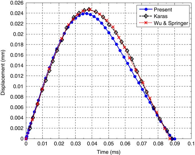
Figure 2 Time history of impactor displacement of an isotropic plate subjected to low-velocity impact predicted by Karas( Reference Karas 33 ), Wu and Springer( Reference Wu 36 ) and present method.

Figure 3 Time history of contact force of isotropic plate subjected to low-velocity impact predicted by Karas( Reference Karas 33 ), Wu and Chung( Reference Wu and Fu-Kuo 34 ), Khalili et al.( Reference Khalili, Malekzadeh and Gorgabad 35 ) and present method.
First of all, the effective material properties of CNTRCs are needed to be determined. Ploy methyl methacrylate, labelled as PMMA, is chosen for the matrix with material properties of ρm=1150 kg/m3, νm=0.34, αm=45(1+0.0005ΔT)×10−6/K and E m=(3.52−0.0034T) GPa, where T=T 0+ΔT and T 0=300 K (room temperature). In this way, αm=45.0×10⁻⁶/K and E m=2.5 GPa at T=300 K. The (10,10) single-walled carbon nanotubes (SWCNTs) are chosen as reinforcements. As listed in Table 1, typical size and temperature-dependent material properties of CNTs are obtained using MD simulations( Reference Shen and Zhang 37 ). It should be mentioned that the manufacturing procedure of (10,10) SWCNTs are described in detail in Ref. Reference Richard, Smalley, Colbert, Guo, Rinzler and Nikolaev38.
Table 1 Temperature-dependent material properties for (10,10) SWCNT (L=9.26 nm, R=0.68 nm, h=0.067 nm and
 $\tf="OT5bf56204_B" {{\rm \rnu }_{{ 12}}^{{\tf="OTc7c3f249_BI" CN}} {\equals}0.175}$
)
$\tf="OT5bf56204_B" {{\rm \rnu }_{{ 12}}^{{\tf="OTc7c3f249_BI" CN}} {\equals}0.175}$
)

Aluminium 2024-T3 is selected for the metal part of CNTML, with temperature-dependent material properties given in Table 2 ( Reference Barron and Barron 39 ). To comprehensively define a CNTML laminate, the following coding system is used. The coding system of nanotube-reinforced aluminium laminate is Al/CNT (1+i)/i, for instance, for i=3, Al/CNT 4/3 defines a laminate composed of four aluminium and three nanotube-reinforced layers stacked together (i.e. Al/CNT/Al/CNT/Al/CNT/AL). In the following examples, the thickness of metal and CNTRC layers are assumed to be h Al=0.2 mm and h CNT=0.3 mm, respectively.
Table 2 Temperature-dependent material properties of aluminium 2024-T3 (ν=0.33 and ρ=2770 kg/m3)( Reference Barron and Barron 39 )

The CNT efficiency parameters η i (i=1,2,3) are crucial in the successful application of the extended rule of mixture to CNTRCs. Unfortunately, no experiments have been done to determine the values of η i for CNTRCs, yet. As it was mentioned before, these parameters can be calculated by matching theoretical results of extended rule of mixture to those of experiments or MD simulations. In this study, the longitudinal and transverse Young’s moduli and in-plane shear moduli of CNTs obtained from MD simulations given by Han and Elliott( Reference Han and Elliott 4 ) are matched to those predicted from the extended rule of mixture in order to estimate the CNT efficiency parameters. As previously presented in Ref. Reference Shen and Zhang37, these parameters are listed in Table 3. In the following examples, these values are used in which it is assumed that G 13=G 12 and G 23=1.2G 12 ( Reference Song and Youn 40 ).
Table 3 (10,10) SWCNT efficiency parameters (L=9.26 nm, R=0.68 nm, h=0.067 nm and
 ${\rm \rnu }_{{\tf="OT5bf56204_B" 12}}^{{{\tf="OT5bf56204_B" CN}}} {\equals}\tf="OT5bf56204_B"0.175$
)
${\rm \rnu }_{{\tf="OT5bf56204_B" 12}}^{{{\tf="OT5bf56204_B" CN}}} {\equals}\tf="OT5bf56204_B"0.175$
)

Three types of FG-CNTRC layers (i.e. FG-Λ, FG-V and FG-X) are considered. A UD-CNTRC layer is also considered for comparison. Also, the deflected mode is assumed to be (m,n)=(1,1). The impactor is made of steel (ρi=7960 kg/m3, E i=207 GPa and νi=0.3) with a radius of R=6.35 mm and an initial velocity of V 0=3 m/s.
The low-velocity impact response of sandwich cylindrical panels with Al/CNT 2/1 face sheets and FG-X core is presented in this section. For all cases below, the cylindrical panel geometric parameters are taken as a=b=200 mm and R/a=5. The Al/CNT 2/1 is selected for sandwich panel face sheets. Also, the CNT layer is assumed to be FG of type X, due to its high strength to impact( Reference Bayat, Rahmani and Mashhadi 41 ). Titanium alloy, referred to as Ti–6Al–4V, and Zirconia are selected as metal and ceramic part of FG core, respectively; the material properties of which are given in Table 4 as a non-linear function of temperature( Reference Reddy and Chin 42 ). The thickness of homogeneous or FG core is taken to be h c=4, 6 and 8 mm.
Table 4 Material property of the constituent materials of the considered FG core as a non-linear function of temperature (P=P 0(P −1/T+1+P 1 T+P 2 T 2+P 3 T 3))( Reference Reddy and Chin 42 )

Low-velocity impact response of sandwich cylindrical panels with Al/CNT 2/1 face sheets and four types of core (i.e. homogenous, FG-Λ, FG-V and FG-X) is displayed in Fig. 4. The panel with FG-X core has the lowest central deflection while the contact forces are almost the same. Also the power index of the FG core, mentioned in Equation (14), can influence the impact response of the sandwich panels with FG cores. Therefore, the impact response of sandwich panels with FG core of type X with five various power indexes is compared in Fig. 5. Using a power index of n=0.1 significantly decreases the central deflection, however, slightly increases the contact force. Hence, the FG core of type X with power index of n=0.1 will be considered in the following examples.

Figure 4 Comparison of the impact response of sandwich cylindrical panels with four types of cores: (a) central deflection and (b) contact force (a/b=1, a=200 mm, R/a=5, h
Al=0.2 mm, h
CNT=0.3 mm, h
core=6 mm, n=1,
 $V_{{{\rm CN}}}^{{\asterisk}} {\equals}0.17$
, V
0=3 m/s and T=300 K).
$V_{{{\rm CN}}}^{{\asterisk}} {\equals}0.17$
, V
0=3 m/s and T=300 K).

Figure 5 The effect of power index of FG core of sandwich panel on the impact response: (a) central deflection and (b) contact force (a/b=1, a=200 mm, R/a=5, h
Al=0.2 mm, h
CNT=0.3 mm, h
core=6 mm,
$V_{{{\rm CN}}}^{{\asterisk}} {\equals}0.17$
, V
0=3 m/s and T=300 K).
The effect of core thickness on the low-velocity impact response of the sandwich cylindrical panel with Al/CNT 2/1 face sheets with CNT volume fraction of
 $V_{{{\rm CN}}}^{{\asterisk}} {\equals}0.12$
and FG-X core with power index of n=0.1 is presented in Fig. 6. The sandwich panel with thicker core has lower central deflection along with a little higher contact force.
$V_{{{\rm CN}}}^{{\asterisk}} {\equals}0.12$
and FG-X core with power index of n=0.1 is presented in Fig. 6. The sandwich panel with thicker core has lower central deflection along with a little higher contact force.

Figure 6 The effect of core thickness on low-velocity impact response of sandwich cylindrical panel with Al/CNT 2/1 face sheets and FG-X core: (a) central deflection and (b) contact force (a/b=1, a=200 mm, R/a=5, h
Al=0.2 mm, h
CNT=0.3 mm, n=0.1,
 $V_{{{\rm CN}}}^{{\asterisk}} {\equals}0.12$
, V
0=3 m/s and T=300 K).
$V_{{{\rm CN}}}^{{\asterisk}} {\equals}0.12$
, V
0=3 m/s and T=300 K).
The low-velocity impact response of sandwich cylindrical panels with various CNT volume fractions is illustrated in Fig. 7. The sandwich panels with higher CNT volume fraction in their CNTML face sheets respond faster to the low-velocity impact than others (i.e. reach to their maximum of central deflection faster) which can be due to their stiffer CNTRC layer. Also, the sandwich panel with the CNT volume fraction of
 $$V_{{{\rm CN}}}^{{\asterisk}} {\equals}0.17$$
of its CNTML face sheet has the lowest central deflection in comparison with others. There is no considerable change in contact force of sandwich panels with three different CNT volume fractions; however, as the CNT volume fraction increases, the contact force decreases slightly.
$$V_{{{\rm CN}}}^{{\asterisk}} {\equals}0.17$$
of its CNTML face sheet has the lowest central deflection in comparison with others. There is no considerable change in contact force of sandwich panels with three different CNT volume fractions; however, as the CNT volume fraction increases, the contact force decreases slightly.

Figure 7 The effect of CNT volume fraction on low-velocity impact response of sandwich cylindrical panel with Al/CNT 2/1 face sheets and FG-X core: (a) central deflection and (b) contact force (a/b=1, a=200 mm, R/a=5, h Al=0.2 mm, h CNT=0.3 mm, h core=8 mm, n=0.1, V 0=3 m/s and T=300 K).
The effect of impactor initial velocity on the low-velocity impact response of sandwich cylindrical panel is presented in Fig. 8. Similar to single-layer CNTRC and CNTML cylindrical panels, the central deflection as well as the contact force of the sandwich panel increases as the impactor initial velocity increases. However, this example can be quantitatively helpful in optimally designing sandwich cylindrical panels with CNTML face sheets and FG core.

Figure 8 The effect of impactor initial velocity on low-velocity impact response of sandwich cylindrical panel with Al/CNT 2/1 face sheets and FG-X core: (a) central deflection and (b) contact force (a/b=1, a=200 mm, R/a=5, h
Al=0.2 mm, h
CNT=0.3 mm, h
core=8 mm, n=0.1,
$V_{{{\rm CN}}}^{{\asterisk}} {\equals}0.17$
and T=300 K).
The effect of temperature on the low-velocity impact response of the sandwich cylindrical panels with ‘immovable’ edge boundary conditions is also illustrated in Fig. 9. The central deflection increases significantly in elevated temperature because of ‘immovable’ boundary condition and thermal effects. However, the contact force changes negligibly.

Figure 9 Low-velocity impact response of sandwich cylindrical panel with Al/CNT 2/1 face sheets and FG-X core in various thermal environments and with ‘immovable’ edge boundary condition: (a) central deflection and (b) contact force (a/b=1, a=200 mm, R/a=5, h
Al=0.2 mm, h
CNT=0.3 mm, h
core=8 mm, n=0.1,
 $V_{{{\rm CN}}}^{{\asterisk}} {\equals}0.28$
and V
0=3 m/s).
$V_{{{\rm CN}}}^{{\asterisk}} {\equals}0.28$
and V
0=3 m/s).
To see the effect of boundary condition, the impact response of sandwich panels with two types of boundary conditions (i.e. ‘movable’ and ‘immovable’) is presented in Fig. 10. Obviously, the central deflection increases considerably when the edge boundary condition is ‘immovable’. As was discussed previously, there is no change in the contact force when the edge boundary condition changes to ‘immovable’.

Figure 10 The effect of edge boundary condition on low-velocity impact response of sandwich cylindrical panel with Al/CNT 2/1 face sheets and FG-X core: (a) central deflection and (b) contact force (a/b=1, a=200 mm, R/a=5, h
Al=0.2 mm, h
CNT=0.3 mm, h
core=8 mm,
 $V_{{{\rm CN}}}^{{\asterisk}} {\equals}0.12$
, V
0=3 m/s and T=500 K).
$V_{{{\rm CN}}}^{{\asterisk}} {\equals}0.12$
, V
0=3 m/s and T=500 K).
6.0 SUMMARY AND CONCLUSION
The non-linear low-velocity impact response of sandwich cylindrical panels with CNTRC and metal face sheets and four types of core (i.e. homogenous, FG-Λ, FG-V and FG-X) in thermal environments was presented. The present method was validated with the existing literature data. A parametric study of various effective parameters on the impact response was conducted. The presented numerical examples demonstrate that the CNT volume fraction, impactor initial velocity and the thermal environment have a significant role on the impact response of CNTRC cylindrical panels. In addition, the effect of geometrical parameters was studied. It was found that functionally grading the CNTRC core with the power index of n=0.1, significantly decreases the central deflection, however, slightly increases the contact force. Also, the sandwich panel with thicker core has been discovered to have lower central deflection along with a little higher contact force. Moreover, the sandwich panels with higher CNT volume fraction in their CNTML face sheets are found to respond faster to the low-velocity impact than others. The presented analysis and numerical results can be useful in optimally designing nanocomposite structures subjected to impact in thermal environments.
Appendix A
In Equations (37) and (38)
 $$\eqalignno{ & {\rm \rtheta }_{2} {\equals}{1 \over 2}\left[ {{{3g_{{33}} } \over {4g_{{31}} }}{\minus}{{5g_{{32}}^{2} } \over {6g_{{31}}^{2} }}} \right],\quad {\rm \rtheta }_{4} {\equals}{1 \over 2}\left[ {{{5g_{{35}} } \over {8g_{{31}} }}{\minus}{{15g_{{33}}^{2} } \over {128g_{{31}}^{2} }}{\plus}{{13g_{{32}}^{2} g_{{33}} } \over {32g_{{31}}^{3} }}{\minus}{{491g_{{32}}^{4} } \over {864g_{{31}}^{4} }}} \right], \cr & g_{{30}} {\equals}{\minus}\left[ {{\rm \rgamma }_{{170}} {\minus}\left( {{\rm \rgamma }_{{171}} m^{2} {\plus}{\rm \rgamma }_{{172}} n^{2} {\rm \rbeta }^{2} } \right)} \right]{\minus}{{{\rm \rgamma }_{{81}} m^{2} g_{{04}} {\plus}{\rm \rgamma }_{{82}} n^{2} {\rm \rbeta }^{2} g_{{03}} } \over {g_{{00}} }} \cr & \quad \quad \quad {\plus}{\rm \rgamma }_{{14}} {\rm \rgamma }_{{24}} {{g_{{05}}^{{\asterisk}} } \over {g_{{06}} }}{{{\rm \rgamma }_{{81}} m^{2} g_{{02}} {\plus}{\rm \rgamma }_{{82}} n^{2} {\rm \rbeta }^{2} g_{{01}} } \over {g_{{00}} }}{\minus}g_{{08}}^{{\asterisk}} {\minus}{\rm \rgamma }_{{14}} {\rm \rgamma }_{{24}} {{g_{{07}}^{{\asterisk}} g_{{05}}^{{{\asterisk}{\asterisk}}} } \over {g_{{06}} }},\quad g_{{31}} {\equals}Q_{{11}} {\minus}D_{{02}} , \cr & g_{{32}} {\equals}{\minus}{2 \over {3\rpi ^{2} mn}}{\rm \rgamma }_{{14}} {\rm \rgamma }_{{24}} m^{2} n^{2} {\rm \rbeta }^{2} \left( {{{{\rm \rgamma }_{8} } \over {{\rm \rgamma }_{6} }}{\plus}{{{\rm \rgamma }_{9} } \over {{\rm \rgamma }_{7} }}{\plus}{1 \over {4m^{2} {\rm \reta \rgamma }_{6} }}{\plus}4{{g_{{05}}^{{\asterisk}} } \over {g_{{06}} }}} \right) \cr & \quad \quad \quad \left( {1{\minus}\cos \left( {m\rpi } \right)} \right)\left( {1{\minus}\cos \left( {n\rpi } \right)} \right){\plus}2g_{{33}} \Phi \left( T \right),\quad g_{{33}} {\equals}{1 \over {16}}{\rm \rgamma }_{{14}} {\rm \rgamma }_{{24}} \left( {{{m^{4} } \over {{\rm \rgamma }_{7} }}{\plus}{{n^{4} {\rm \rbeta }^{4} } \over {{\rm \rgamma }_{6} }}} \right){\minus}D_{{22}} , \cr & (g_{{34}} ,g_{{35}} ){\equals}\left( {{{K_{c} a^{2} } \over {\rpi ^{2} D_{{11}}^{{\asterisk}} }},{\minus}{{K_{c} a^{2} \rrho _{0} } \over {m^{i} \rpi ^{2} E_{0} }}} \right)\left[ {D_{{11}}^{{\asterisk}} D_{{22}}^{{\asterisk}} A_{{11}}^{{\asterisk}} A_{{22}}^{{\asterisk}} } \right]^{{1\,/\,8}} \cr & g_{{220}} {\equals}{\rm \rgamma }_{{14}} {\rm \rgamma }_{{24}} n^{2} {\rm \rbeta }^{2} \left( {{{4m^{2} {\rm \rgamma }_{8} {\plus}{\rm \reta }^{{{\minus}1}} } \over {8{\rm \rgamma }_{6} }}{\plus}m^{2} {{g_{{05}}^{{\asterisk}} } \over {g_{{06}} }}} \right), \cr & g_{{202}} {\equals}{\rm \rgamma }_{{14}} {\rm \rgamma }_{{24}} m^{2} n^{2} {\rm \rbeta }^{2} \left( {{1 \over 2}{{{\rm \rgamma }_{9} } \over {{\rm \rgamma }_{7} }}{\plus}{{g_{{05}}^{{\asterisk}} } \over {g_{{06}} }}} \right) $$
in which (with other symbols given as in Refs Reference Shen and Xiang43,45)
 $$\eqalignno{ & Q_{{11}} {\equals}g_{{08}} {\plus}{\rm \rgamma }_{{14}} {\rm \rgamma }_{{24}} {{g_{{05}}^{{\asterisk}} g_{{07}}^{{\asterisk}} } \over {g_{{06}} }}, \cr & D_{{02}} {\equals}{\rm \rgamma }_{{14}} \left( {B_{{00}}^{{\left( 0 \right)}} m^{2} {\plus}b_{{00}}^{{\left( 0 \right)}} n^{2} {\rm \rbeta }^{2} } \right),\quad D_{{22}} {\equals}{\rm \rgamma }_{{14}} \left( {B_{{00}}^{{\left( 2 \right)}} m^{2} {\plus}b_{{00}}^{{\left( 2 \right)}} n^{2} {\rm \rbeta }^{2} } \right), \cr & \Phi (T){\equals}{\rm \rlambda }{\plus}\Theta _{2} ({\rm \rlambda })^{2} {\plus}\Theta _{3} ({\rm \rlambda })^{3} {\plus} \cdots $$
also
 $$\Phi (T){\equals}{\rm \rlambda }{\plus}\Theta _{2} ({\rm \rlambda })^{2} {\plus}\Theta _{3} ({\rm \rlambda })^{3} {\plus} \cdots $$
where
 $$\eqalignno{ & {\rm \rlambda }{\equals}{{16} \over {\rpi ^{2} G_{{08}} }}\left( {\left( {{\rm \rgamma }_{{T3}} m^{2} {\plus}{\rm \rgamma }_{{T4}} n^{2} {\rm \rbeta }^{2} } \right){\minus}{{\left( {{\rm \rgamma }_{{T3}} {\minus}{\rm \rgamma }_{{T6}} } \right)m^{2} g_{{102}} {\plus}\left( {{\rm \rgamma }_{{T4}} {\minus}{\rm \rgamma }_{{T7}} } \right)n^{2} {\rm \rbeta }^{2} g_{{101}} } \over {g_{{00}} }}} \right)\Delta T \cr & \quad \quad {\times}{h \over {\left[ {D_{{11}}^{{\asterisk}} D_{{22}}^{{\asterisk}} A_{{11}}^{{\asterisk}} A_{{22}}^{{\asterisk}} } \right]^{{1\,/\,4}} }}, \cr & \Theta _{2} {\equals}{8 \over {3\rpi ^{2} G_{{08}} }}{\rm \rgamma }_{{14}} {\rm \rgamma }_{{24}} m^{2} n^{2} {\rm \rbeta }^{2} \left( {{{{\rm \rgamma }_{8} } \over {{\rm \rgamma }_{6} }}{\plus}{{{\rm \rgamma }_{9} } \over {{\rm \rgamma }_{7} }}{\plus}{1 \over {4m^{2} \reta {\rm \rgamma }_{6} }}{\plus}4{{g_{{05}}^{{\asterisk}} } \over {g_{{06}} }}} \right), \cr & \Theta _{3} {\equals}2\Theta _{2}^{2} {\minus}{{g_{{33}} } \over {Q_{{11}} {\minus}D_{{02}} }} $$
For ‘movable’ edge boundary condition
 $$B_{{00}}^{{\left( 0 \right)}} {\equals}B_{{00}}^{{\left( 2 \right)}} {\equals}b_{{00}}^{{\left( 0 \right)}} {\equals}b_{{00}}^{{\left( 2 \right)}} {\equals}0,\,\,$$
and for ‘immovable’ edge boundary condition
 $$\eqalignno{ & B_{{00}}^{{\left( 0 \right)}} {\equals}{\rm \reta }^{{{\minus}1}} {\rm \rgamma }_{{T1}} \Delta T,\quad B_{{00}}^{{\left( 2 \right)}} {\equals}{\minus}{1 \over 8}{\rm \rgamma }_{{24}} {{m^{2} {\plus}{\rm \rgamma }_{5} n^{2} {\rm \rbeta }^{2} } \over {\rgamma _{{24}}^{2} {\minus}{\rm \rgamma }_{5}^{2} }}, \cr & b_{{00}}^{{\left( 0 \right)}} {\equals}{\rm \reta }^{{{\minus}1}} {\rm \rgamma }_{{T2}} \Delta T,\quad b_{{00}}^{{\left( 2 \right)}} {\equals}{\minus}{1 \over 8}{\rm \rgamma }_{{24}} {{{\rm \rgamma }_{5} m^{2} {\plus}{\rm \rgamma }_{{24}}^{2} n^{2} {\rm \rbeta }^{2} } \over {{\rm \rgamma }_{{24}}^{2} {\minus}{\rm \rgamma }_{5}^{2} }}. $$


