


1.0 INTRODUCTION
Machine-driven aircraft assembly can be carried out much faster, applying higher drilling and riveting forces compared to those processes provided by humans(Reference Sarh, Buttrick, Munk and Bossi1). From the operator perspective, the impact of the following factors may be mitigated with automation: positions that are hard to reach; damage to body joints due to tool vibration; hearing hazard due to tool noise; and breathing hazard resulting from the use of sealants as well as carbon dust due to the increased use of composites in aircraft design.
P J Crothers et al.(Reference Crothers, Nesbit, Steele, Lam, Gower, Van Duin and Newberry2) state that the aerospace industry has tended to use large, heavy, and custom-made automation equipment for the characteristics of accuracy, scale, and process force. They are projected to be stiff and large enough to cover the entire product envelope delivering the necessary accuracy. Besides the high cost, such systems also require a custom foundation and a large floor area. As such, a reasonable payback for these systems tend to require higher-volume and larger-scale operations.
Smaller and less expensive machines have risen as a possible alternative to replace traditional equipment. The term lightweight automation has been coined(Reference Crothers, Nesbit, Steele, Lam, Gower, Van Duin and Newberry2) to encompass solutions based on regular industrial manipulators integrated with metrology systems and other affordable options such as parallel kinematic robots that present increased stiffness as major characteristic. Figure 1 shows the final stage of the alignment procedure of two fuselage barrels from a commercial aircraft as an example of the lightweight automation that is being implemented at the Aircraft Structure Assembly Automation Laboratory (ASAA Lab) of the Aeronautics Institute of Technology (ITA-Brazil).

Figure 1. Partial view of the ASAA fuselage assembly cell.
The automated process developed by the ASAA Lab focuses on the assembly of two fuselage sections and consists of two main phases: the alignment of the fuselage sections and the drilling and riveting procedures that join the sections together. These phases are divided and organized in a sequence of operations performed by the robotic cell. M L Simonetti and L G Trabasso(Reference Simonetti and Trabasso3) proposed a conceptual draft of the operation sequence for the ASAA process prior to the work presented herein.
The sequence consists of the four operations depicted in Fig. 2. In the first operation, the fuselage sections are delivered and the cell is brought to its initial position. In the second operation, a coarse alignment is performed. While in the third operation, a fine-tuning alignment takes place. Finally, in the fourth operation, the assembly is completed with the drilling and riveting procedures(Reference Negroni and Trabasso4).

Figure 2. Virtual simulation of the ASAA process. Source(Reference Vieira5).
The aircraft structure joining operations are the most complex and therefore the longest in terms of the required labor hours(Reference Smith, Zieve and Gurievsky6). The work of the ASAA Lab is justified by the implementation of alignment alternatives that are less expensive and more flexible(Reference Simonetti and Trabasso3). This arrangement is possible in part due to the use of industrial manipulators in the alignment of fuselages and the fact that they offer good repeatability, modularity, flexibility of use, and low cost compared to other traditional systems.
The main contribution of the work presented herein is the analysis of the preselected solutions for the alignment stage, and as result reference values for the performance of alignment systems based on the combination of industrial manipulators and metrology systems. Contrary to J D Barnfather et al.(Reference Barnfather, Goodfellow and Abram7), which deals with similar problem but uses hexapod robots, this work attains to anthropomorphic, commercial off-the -shelf (COTS) industrial robots.
The alignment of the aircraft fuselage is guided by three major tolerance parameters (see Fig. 3). The gap parameter is measured along the longitudinal axis of the aircraft and describes the border-to-border distance between two consecutive fuselage sections. The step parameter is measured along the transversal axes of the aircraft and describes the distance between the center of the two borders. The angulation parameter is described by the angle formed by the longitudinal axes of the fuselage sections. The alignment tolerance criteria adopted for this project match those of a 50-seater regional jet: between 0.8 and 1.5mm gap, a maximum of 0.1mm step, and a maximum of
 $0.05^\circ$
angulation.
$0.05^\circ$
angulation.

Figure 3. Major tolerance parameters for the alignment of aircraft fuselages.
The structure of this article is as follows: Section 2 presents a literature review in the realm of automated solution for aircraft assembly; Section 3 describes the operating principles of the equipment used in this work; then Section 4 describes the method used to investigate the proposed problem; while Sections 5 and 6 present the results and conclusions reached, respectively.
2.0 RELATED WORK
H Kihlman(Reference Kihlman8) presents an extensive study on the current alternatives for affordable automation within the aeronautical domain. The work evaluates the market data that justify lightweight automation and reviews the requirements and procedures of modern aircraft assembly techniques. Furthermore, it presents an overview of equipment used in orbital drilling and metrology-integrated robotics, including current trends. Finally, it notes that robots may replace traditional machines in some areas, but not completely as shown in Fig. 4. The following subsections review works focusing on both traditional and lightweight solutions.
Figure 4. Appropriate automation solution according to production volume.
In the past decades, lightweight automation solutions based upon industrial robots have been widely used in the automotive industry(Reference Yagi9). On the one hand, they have been used mainly in welding and pick-and-place operations, driving their development toward good repeatability (typically
 $< \pm0.1\text{mm}$
). On the other hand, only more recently, the aerospace industry has started to adopt the solutions and potential benefits brought by lightweight automation and has faced difficulties in implementing pre-existent technology. Positional accuracy in aircraft assembly (in the order of
$< \pm0.1\text{mm}$
). On the other hand, only more recently, the aerospace industry has started to adopt the solutions and potential benefits brought by lightweight automation and has faced difficulties in implementing pre-existent technology. Positional accuracy in aircraft assembly (in the order of
 $\pm0.20\text{mm}$
) is roughly a tenth of what those robots can deliver. Therefore, to benefit from their low-cost, flexible automation, some sort of correction and compensation mechanism becomes imperative to allow the use of industrial manipulators in aircraft assembly as depicted in Fig. 5.
$\pm0.20\text{mm}$
) is roughly a tenth of what those robots can deliver. Therefore, to benefit from their low-cost, flexible automation, some sort of correction and compensation mechanism becomes imperative to allow the use of industrial manipulators in aircraft assembly as depicted in Fig. 5.

Figure 5. Possible workarounds to overcome manipulator limitations in positioning accuracy.
Yet another possibility to improve robot accuracy is calibration methods embedded in an integrated design framework of CAD-based simulations and offline programming(Reference Leali, Vergnano, Pini, Pellicciari and Berselli10). S Costa(Reference Costa11) argues that the reasons behind the increased demand for automation in the aerospace sector include not only the need to reduce costs but also to improve product quality. New requirements imposed on automation design demand that cells be flexible enough to handle multiple products and/or configurations. Starting from these requirements, his work presents the main concepts of an adaptive assembly cell developed by Dassault for the assembly of the Rafale fighter. The solution employs industrial manipulators as mobility machines and the need for a corrective system is recognized.
One corrective solution is to update the kinematic model of manipulators by means of a mathematical optimization process and calibration data from the robot. Because of manufacturing imperfections and fluctuations, each robot differs slightly from the parameters contained in its theoretical model. Major robot manufacturers offer calibration packages that yield a higher accuracy(12, 13). These packages consider the exact robot parameters such as link lengths as well as payload mass and center of mass and supplementary payload mass to calculate an optimized kinematic model. This in turn enables the robot controller to account for dynamic loads, improving acceleration and braking, and avoiding overshooting the target point, thus resulting in improved accuracy.
A variation of kinematic model improvements is a correction table that contains expected robot and machine positioning error throughout its work envelope. The technique used to generate this table is called software compensation and employs a parametric model to turn data collected at several workspace points into an error estimative. P A Freeman(Reference Freeman14) presents a software compensation method based on laser tracker technology to generate the error parameters, claiming an improvement in machine accuracy up to 80%, approaching the machine repeatability values. In this case, metrology is part of the process, but it is not used in online corrections.
Arm deflection due to load and gear backlash in the joints also accounts for part of the loss in the accuracy of manipulators. Due to their nature, these deviations cannot be detected by internal encoders in the joint that is the standard feedback source for robot control. Additional encoders, placed on the outside structure of the manipulator (i.e., external encoders), have risen as a possible alternative to compensate for these shortcomings(Reference Devlieg and Szallay15–Reference Devlieg18).
Another solution to the problems of parameter fluctuation, deflection, and backlash is to use metrology to feed robots with corrected position data. Metrology feedback corrects the target position directly rather than updating the kinematic model. W Estler(Reference Estler, Edmundson, Peggs and Parker19) presents a general review of the technologies behind current large-volume metrology. Current non-contact metrology systems are based on many modern technologies; two major ones are laser and photogrammetry. In the laser category, two main products are the NikonTM Indoor Global Positioning System (iGPS) and the NikonTM Laser Radar large volume point scanner (LR); both are large volume metrology systems. The NikonTM K-610 photogrammetric camera (K-610) is a major player in its category. These three equipments are described in Section 3 and used in the research described herein. While the iGPS and the K-610 are tracking mechanisms, meaning that they can measure a dynamic target, the LR offers a higher measuring accuracy (>10x and >2x when compared to the iGPS and the K-610, respectively) and is thus suitable for assessing the performance of these systems, although it can only perform static measurements.
In a previous work from the ASAA Lab, E Villani et al.(Reference Villani, Suterio, Trabasso, Furtado, Alvarado and Amorim20) present independent performance evaluations of industrial robots in the aircraft assembly process using the iGPS and the K-610. The results motivated a more careful analysis(Reference Mosqueira, Apetz, Santos, Villani, Suterio and Trabassoa21) for the iGPS and herein for the K-610.
B Marguet and B Ribere (Reference Marguet and Ribere22) describe a measurement-assisted assembly based on laser tracker to reduce drastically assembly time in both fuselage-to-fuselage and fuselage-to-wing junctions, eliminating most of the need for large, dedicated tooling. They have also enumerated the steps necessary to deploy a measurement-assisted assembly.
Z Zhang et al.(Reference Zhang, Li, Han and Gao23) show a similar approach of that described herein for a far simpler assembly task: the tube assembly.
M Summers(Reference Summers24) presents a robot capability analysis based on several key criteria, including the kinematic model, static and dynamic loading, external process forces, temperature drift, and gearbox rigidity, showing how standard manipulators fail to meet the tolerances specified by aeronautical processes. An online correction method based on an older version of the K-610 (the K-600) and offline programming software is suggested to achieve aeronautical positioning criteria.
3.0 EQUIPMENT WORKING PRINCIPLES
3.1 Laser radar
The laser radar (LR) is a large-volume, frequency-modulated measurement system. It makes static readings, meaning it has no tracking capabilities. The LR determines the position of a given point in space through spherical coordinates. The azimuth and elevation components are obtained with encoders placed on the two motors that move its steerable mirror. The range is calculated through the emission of a saw-tooth wave that reflects on surfaces and returns to the equipment. The working principle behind this is based on the frequency shift,
 $\Delta f$
, of the returned wave compared to a control wave (Fig. 6, left). There is a corresponding time difference,
$\Delta f$
, of the returned wave compared to a control wave (Fig. 6, left). There is a corresponding time difference,
 $\Delta t$
, but its value is too small and thus too hard to be measured. The control wave goes through a calibrated loop of optical fiber known as the local oscillator (LO). Each LO is adjusted to give a frequency shift of zero when compared to a wave returned from a target at a given distance. If the target distance is at a smaller or at a greater value, the frequency shift increases. By combining the information of multiple LOs, it is possible to determine the distance of the target (Fig. 6, right).
$\Delta t$
, but its value is too small and thus too hard to be measured. The control wave goes through a calibrated loop of optical fiber known as the local oscillator (LO). Each LO is adjusted to give a frequency shift of zero when compared to a wave returned from a target at a given distance. If the target distance is at a smaller or at a greater value, the frequency shift increases. By combining the information of multiple LOs, it is possible to determine the distance of the target (Fig. 6, right).

Figure 6. The LR head (top left), frequency shift of the reflected beam (bottom left), and range given by LOs (right).
The LR principle described herein is general; however, the setup of this equipment described in Section 4.1 is specific for the aeronautical structural assembly. A similar approach can be found for other sectors. For example, E Kiraci et al.(Reference Kiraci, Franciosa, Turley, Olifent, Attridge and Williams25) describe the LR usage for the automotive sector.
3.2 Photogrammetric camera head K-610
The K-610 is a portable coordinate measuring machine (CMM). The main system is composed of a controller, a camera body with three sensing elements, a probe, and light emitting diode (LED) devices. The LEDs are the targets that allow the identification and tracking of an object. Each sensing element sweeps a plane in space, and the intersection of the three planes yield the point location of an LED (Fig. 7). Three or more LEDs can be combined to yield the 6 degrees of freedom (DOF) of a rigid body. The product data sheet claims a volumetric accuracy of up to
 $60\mu\text{m}$
(
$60\mu\text{m}$
(
 $2\sigma$
) in a
$2\sigma$
) in a
 $17\text{m}^{2}$
field of view and up to a 6 m depth of field of measurement. The system features a temperature compensation model in the
$17\text{m}^{2}$
field of view and up to a 6 m depth of field of measurement. The system features a temperature compensation model in the
 $10{-}35^\circ\text{C}$
range. The maximum measurement frequency for the LED arrangement used in this work is 232 Hz and it can dynamically reference a single LED moving at 300mm/s and with 2g acceleration (26). A previous work from the ASAA Lab(Reference Amorim, Sutério and Trabasso27) presents the K-610 in more detail.
$10{-}35^\circ\text{C}$
range. The maximum measurement frequency for the LED arrangement used in this work is 232 Hz and it can dynamically reference a single LED moving at 300mm/s and with 2g acceleration (26). A previous work from the ASAA Lab(Reference Amorim, Sutério and Trabasso27) presents the K-610 in more detail.

Figure 7. Sensing range of the K-610 per linear sensing camera.
3.3 KR-210 and KR-500 KUKA industrial robots
The KR-210 robot and the KR-500 robot used at the ASAA Lab are standard anthropomorphic industrial manipulators with 6 DOF. The KR-210 has a 7 DOF given by an external axis. The KR-210 is used to carry the ASAA drilling and fastening end-effector and thus is not discussed in this paper. Detailed information about it can be found elsewhere(Reference Furtado, Villani, Trabasso and Silva28). All the relevant network considerations are shared with the KR-500. A previous work from the ASAA Lab presents a discussion of their use in cooperative mode(Reference Santos and Trabasso29). Table 1 summarizes relevant information about the KR-500 robot given by the manufacturer, and more details such as dynamic loading and payload inertia constraints can be found in the literature(30).
Table 1 KR-500 technical data

3.4 AdaptiveFootnote 1 robot control
Adaptive Robot Control (ARC) is a correction and compensation algorithm that integrates robot movement with the iGPS metrology readings. Commercially it is available as software by Nikon TM. A schematic of its working mechanism is presented in Fig. 8. Sensors are placed in the fixture that holds the target part and in the robot tool. This way the relationship between the part and the tool is always known, even if the fixture or the tool are moved. The only requirement is that the sensors must stay rigidly attached to the fixture or tool. The robot moves to the desired position and then the K610 system compares the real attained position to the nominal value. Then it sends the calculated position correction to the robot and this routine is executed in a loop until the desired robot positioning error tolerance is achieved or until a predefined timeout occurs. The dashed box denotes the K610 readings verification with LR, a process that is not part of ARC, but is executed in the experiments described in Section 4.

Figure 8. The ARC correction and compensation algorithm.
4.0 METHODS
4.1 Equipment setup
The establishment of data, references, and coordinate frames are core definitions for the assembly of aircraft components. The data adopted in this work are derived directly from the current version used in industry for manual alignment. In this process, four reference holes located on each fuselage section are used to position in on a jig. Each jig allows the section to be moved in predetermined DOFs. Once the jigs are correctly positioned, a lock-pin is inserted between two adjacent jigs to confirm the correct alignment of the sections as shown in Fig. 9. In the automated cell, the references are created by scanning the same holes with the LR to create a coordinate system that can be used by the robot: the Tool Center Point (TCP).

Figure 9. Assembly references used in the manual process.
The TCP is created from other intermediary systems and starts with the creation of the robot flange system—
 $\text{F}_{\text{KR}500}$
—where the tool is connected. A point cloud is used to identify the flange cylinder, forming the z-axis. Another point cloud identifies the upper plane of the flange, and by an intersection with the z-axis, the origin of the system is determined. A group of points obtained by moving the robot back-and-forth in a fixed direction is used to identify the y-axis and thus complete the definition of
$\text{F}_{\text{KR}500}$
—where the tool is connected. A point cloud is used to identify the flange cylinder, forming the z-axis. Another point cloud identifies the upper plane of the flange, and by an intersection with the z-axis, the origin of the system is determined. A group of points obtained by moving the robot back-and-forth in a fixed direction is used to identify the y-axis and thus complete the definition of
 $F_{KR500}$
, with the x-axis being a consequence (Fig. 10). Finally, four tooling spheres mounted on the flange are used as reference to update
$F_{KR500}$
, with the x-axis being a consequence (Fig. 10). Finally, four tooling spheres mounted on the flange are used as reference to update
 $F_{KR500}$
(the LR is a static measurement tool) without the need to repeat all the previous steps
$F_{KR500}$
(the LR is a static measurement tool) without the need to repeat all the previous steps

Figure 10. Creation of FKR500.
The next step is the creation of the TCP frame (
 $F_{TCP}$
– Fig. 11) based on the index plan shown previously in Fig. 9. The four tooling holes in the fuselage are scanned and fitted to a plane. The test fuselage used in this work had the holed filled with a fastener so that was used instead. Figure 11 (right) shows scans and a picture of the actual rivet. A temporary frame on the center of the plane is then brought forward along the center axis of the fuselage to the farthest point on the edge in the alignment side, and
$F_{TCP}$
– Fig. 11) based on the index plan shown previously in Fig. 9. The four tooling holes in the fuselage are scanned and fitted to a plane. The test fuselage used in this work had the holed filled with a fastener so that was used instead. Figure 11 (right) shows scans and a picture of the actual rivet. A temporary frame on the center of the plane is then brought forward along the center axis of the fuselage to the farthest point on the edge in the alignment side, and
 $F_{TCP}$
is created. This process is necessary to prevent a collision at the edge with another fuselage section, given the test fuselage was taken from a retired aircraft and its cross section is not flat.
$F_{TCP}$
is created. This process is necessary to prevent a collision at the edge with another fuselage section, given the test fuselage was taken from a retired aircraft and its cross section is not flat.
 $F_{TCP}$
is then tied to reference points.
$F_{TCP}$
is then tied to reference points.
 $F_{TCP}$
is then imported into the robot controller through an available teach-in.
$F_{TCP}$
is then imported into the robot controller through an available teach-in.

Figure 11. Creation of FTCP (left) and tooling holes scanning (right).
The references created statically with the LR need to be transferred to the K-610 to allow a dynamic tracking of the fuselage and thus the alignment by the robot. Figure 12 shows how this is accomplished. Reference spheres that can be read by both equipments physically represent
 $\text{F}_{K610}$
. With frames created in both interfaces representing the same physical features, other data such as
$\text{F}_{K610}$
. With frames created in both interfaces representing the same physical features, other data such as
 ${F}_{K610}$
can be exchanged. This step would become unnecessary if both equipments shared the same interface, which is a technically possible improvement that may be implemented in the future.
${F}_{K610}$
can be exchanged. This step would become unnecessary if both equipments shared the same interface, which is a technically possible improvement that may be implemented in the future.

Figure 12. Transferring datums between the LR and the K-610.
Figure 13 contains an overview of the frames for the K-610 setup.
 $F_{Ref}$
is directly defined at the second fuselage section, thus making the reference frame relative rather than global. This reduces the number of frames by one. It also simplifies the process by creating a direct link between
$F_{Ref}$
is directly defined at the second fuselage section, thus making the reference frame relative rather than global. This reduces the number of frames by one. It also simplifies the process by creating a direct link between
 $F_{TCPt}$
and
$F_{TCPt}$
and
 $F_{Ref}$
, which is the target relationship. The LR is used to create all the needed frames while sitting still. The relationship between
$F_{Ref}$
, which is the target relationship. The LR is used to create all the needed frames while sitting still. The relationship between
 $F_{TCPt}$
and
$F_{TCPt}$
and
 $F_{FKR500}$
is used to change the standard robot reference through a KUKA built-in teach pendant. The relationship between
$F_{FKR500}$
is used to change the standard robot reference through a KUKA built-in teach pendant. The relationship between
 $F_{TCPt}/F_{Ref}$
and
$F_{TCPt}/F_{Ref}$
and
 $F_{K610}$
is used by the K-610 to calculate the correct positioning. The features can be dynamically tracked, and the closed-loop alignment can take place once the frames are transferred to the K-610.
$F_{K610}$
is used by the K-610 to calculate the correct positioning. The features can be dynamically tracked, and the closed-loop alignment can take place once the frames are transferred to the K-610.

Figure 13. Full data for the K-610.
An automated routine has been created to read designated reference points automatically. This allows the LR to check automatically the correction of the K-610 provided there is a halt between movements to allow static stabilization.
4.2 EN ISO 9283: a robot evaluation standard
The EN ISO 9283(31) was set to evaluate the performance characteristics of industrial manipulators. However, due to the nature of the work described herein—the evaluation of an enhanced assembly process rather than a robot on its own—the process requirements specified in the norm cannot be met entirely and thus must be slightly altered during the experiments. A brief overview of the EN ISO 9283 experimental pattern is given in this section and those conditions deviating from the norm principles are discussed in Section 5. As per EN ISO 9283, pose accuracy expresses “the deviation between a command pose and the mean of the attained poses when approaching the command pose from the same direction. It is composed of:
Positioning accuracy
 ${AP}_{P}$
: the difference between the position of a command pose and the barycenter of the attained positions (see Fig. 14, left);
${AP}_{P}$
: the difference between the position of a command pose and the barycenter of the attained positions (see Fig. 14, left);

Figure 14. Accuracy and repeatability of positioning (left) and orientation (right). Source(Reference Amorim, Sutério and Trabasso27).
Orientation accuracy
 ${AP}_{a}$
,
${AP}_{a}$
,
 ${AP}_{b}$
,
${AP}_{b}$
,
 ${AP}_{c}$
: the difference between the orientation of a command pose and the average of the attained orientations (see Fig. 14, right)”(31).
${AP}_{c}$
: the difference between the orientation of a command pose and the average of the attained orientations (see Fig. 14, right)”(31).
Pose repeatability expresses “the closeness of agreement between the attained pose after n repeat visits to the same command pose in the same direction. For a given pose, the repeatability is expressed by:
Radius RPl: the radius of the sphere whose center is the barycenter (see Fig. 14, left);
Spread of angles
 $\pm 3{S}_{a}$
,
$\pm 3{S}_{a}$
,
 $\pm 3{S}_{b}$
,
$\pm 3{S}_{b}$
,
 $\pm 3{S}_{c}$
about the mean values
$\pm 3{S}_{c}$
about the mean values
 $\skew3\overline{a}$
,
$\skew3\overline{a}$
,
 $\skew3\overline{b}$
and
$\skew3\overline{b}$
and
 $\skew3\overline{c}$
, where
$\skew3\overline{c}$
, where
 ${S}_{a}$
 ${S}_{b}$
and
${S}_{b}$
and
 ${S}_{c}$
are the standard deviations (see Fig. 14, right)”(31).
${S}_{c}$
are the standard deviations (see Fig. 14, right)”(31).
The described values are calculated as follows.
Positioning accuracy:
Let values
 $\skew3\overline{x}$
,
$\skew3\overline{x}$
,
 $\overline{y}$
, and
$\overline{y}$
, and
 $\overline{z}$
be the coordinates of the barycenter of the cluster of points obtained after repeating the same pose n times. Let
$\overline{z}$
be the coordinates of the barycenter of the cluster of points obtained after repeating the same pose n times. Let
 ${x}_{c}$
,
${x}_{c}$
,
 ${y}_{c}$
, and
${y}_{c}$
, and
 ${z}_{c}$
be the coordinates of the command pose and
${z}_{c}$
be the coordinates of the command pose and
 ${x}_{j}$
,
${x}_{j}$
,
 ${y}_{j}$
, and
${y}_{j}$
, and
 ${z}_{j}$
be the coordinates of the j-th attained pose. Then the positioning accuracy
${z}_{j}$
be the coordinates of the j-th attained pose. Then the positioning accuracy
 ${AP}_{P}$
is calculated by:
${AP}_{P}$
is calculated by:
 \begin{equation}
{AP}_P=\sqrt{{(\skew3\overline{x}-x_c)}^2+{(\overline{y}-y_c)}^2+{(\overline{z}-z_c)}^2}
\label{eqn1}
\end{equation}
\begin{equation}
{AP}_P=\sqrt{{(\skew3\overline{x}-x_c)}^2+{(\overline{y}-y_c)}^2+{(\overline{z}-z_c)}^2}
\label{eqn1}
\end{equation}
with
 \begin{equation}
\skew3\overline{x}=\frac{1}{n}\sum\nolimits^n_{j=1}{x_j},\ \overline{y}=\frac{1}{n}\sum\nolimits^n_{j=1}{y_j},\ \overline{z}=\frac{1}{n}\sum\nolimits^n_{j=1}{z_j}
\label{eqn2}
\end{equation}
\begin{equation}
\skew3\overline{x}=\frac{1}{n}\sum\nolimits^n_{j=1}{x_j},\ \overline{y}=\frac{1}{n}\sum\nolimits^n_{j=1}{y_j},\ \overline{z}=\frac{1}{n}\sum\nolimits^n_{j=1}{z_j}
\label{eqn2}
\end{equation}
Orientation accuracy:
With
 $\skew3\overline{a}$
,
$\skew3\overline{a}$
,
 $\skew3\overline{b}$
, and
$\skew3\overline{b}$
, and
 $\skew3\overline{c}$
as the mean values of the angles obtained at the same pose repeated n times,
$\skew3\overline{c}$
as the mean values of the angles obtained at the same pose repeated n times,
 ${a}_{c}$
,
${a}_{c}$
,
 ${b}_{c}$
, and
${b}_{c}$
, and
 ${c}_{c}$
as the angles of the command pose and
${c}_{c}$
as the angles of the command pose and
 ${a}_{j}$
,
${a}_{j}$
,
 ${b}_{j}$
, and cj as the angles of the j-th attained pose, the orientation accuracy
${b}_{j}$
, and cj as the angles of the j-th attained pose, the orientation accuracy
 ${AP}_{a}$
,
${AP}_{a}$
,
 ${AP}_{b}$
, and
${AP}_{b}$
, and
 ${AP}_{c}$
are calculated by:
${AP}_{c}$
are calculated by:
 \begin{equation}
{AP}_a=\left(\skew3\overline{a}-a_c\right)\!,\ {AP}_b=\left(\skew3\overline{b}-b_c\right)\!,\ {AP}_c=\left(\skew3\overline{c}-c_c\right)
\label{eqn3}
\end{equation}
\begin{equation}
{AP}_a=\left(\skew3\overline{a}-a_c\right)\!,\ {AP}_b=\left(\skew3\overline{b}-b_c\right)\!,\ {AP}_c=\left(\skew3\overline{c}-c_c\right)
\label{eqn3}
\end{equation}
with
 \begin{equation}
\skew3\overline{a}=\frac{1}{n}\sum\nolimits^n_{j=1}{a_j},\ \skew3\overline{b}=\frac{1}{n}\sum\nolimits^n_{j=1}{b_j},\ \skew3\overline{c}=\frac{1}{n}\sum\nolimits^n_{j=1}{c_j}
\label{eqn4}
\end{equation}
\begin{equation}
\skew3\overline{a}=\frac{1}{n}\sum\nolimits^n_{j=1}{a_j},\ \skew3\overline{b}=\frac{1}{n}\sum\nolimits^n_{j=1}{b_j},\ \skew3\overline{c}=\frac{1}{n}\sum\nolimits^n_{j=1}{c_j}
\label{eqn4}
\end{equation}
Positioning repeatability:
With
 $\skew3\overline{x}$
,
$\skew3\overline{x}$
,
 $\overline{y}$
, and
$\overline{y}$
, and
 $\overline{z}$
as well as
$\overline{z}$
as well as
 ${x}_{j}$
,
${x}_{j}$
,
 ${y}_{j}$
, and
${y}_{j}$
, and
 ${z}_{j}$
defined previously, the positioning repeatability
${z}_{j}$
defined previously, the positioning repeatability
 ${RP}_{l}$
is calculated by:
${RP}_{l}$
is calculated by:
 \[{RP}_l=\ \skew2\overline{l}+3S_l,\]
where
 \begin{equation} \overline{l}=\frac{1}{n}\sum^n_{j=1}{l_j},\\ l_j=\sqrt{{(x_j-\overline{x})}^2+{( y_j-\overline{y})}^2+{(z_j-\overline{z})}^2}, \\ S_l=\sqrt{\frac{\sum^n_{j=1}{{(l_j-\skew2\overline{l})}^2}}{n-1}} \end{equation}
Orientation repeatability:
The orientation repeatability terms
 ${RP}_{a}$
,
${RP}_{a}$
,
 ${RP}_{b}$
, and
${RP}_{b}$
, and
 ${RP}_{c }$
are calculated by:
${RP}_{c }$
are calculated by:
 \begin{gather*}
{RP}_a=\ \pm 3S_a=\ \pm 3\sqrt{\frac{\sum^n_{j=1}{{(a_j-\skew3\overline{a})}^2}}{n-1}},\\
{RP}_b=\ \pm 3S_b=\ \pm 3\sqrt{\frac{\sum^n_{j=1}{{(b_j-\skew3\overline{b})}^2}}{n-1}}, \\
{RP}_c=\ \pm 3S_c=\ \pm 3\sqrt{\frac{\sum^n_{j=1}{{(c_j-\skew3\overline{c})}^2}}{n-1}}
\end{gather*}
\begin{gather*}
{RP}_a=\ \pm 3S_a=\ \pm 3\sqrt{\frac{\sum^n_{j=1}{{(a_j-\skew3\overline{a})}^2}}{n-1}},\\
{RP}_b=\ \pm 3S_b=\ \pm 3\sqrt{\frac{\sum^n_{j=1}{{(b_j-\skew3\overline{b})}^2}}{n-1}}, \\
{RP}_c=\ \pm 3S_c=\ \pm 3\sqrt{\frac{\sum^n_{j=1}{{(c_j-\skew3\overline{c})}^2}}{n-1}}
\end{gather*}
5.0 EXPERIMENTAL PROCEDURE
The proof-of-concept robotic aircraft assembly cell is due to work in non-air-conditioned production halls. Therefore, the experiments were conducted at an ambient temperature between 20 and
 ${25}^\circ \text{C}$
for the K-610 experiments. The same reasoning also applies to the load conditions: Instead of 100% of the rated payload (480 kg for the KR-500), the intended payload (i.e., the fuselage ring with a mass of 343.8 kg) has been mounted to the robot flange. This large volume payload necessitates an adjustment of the path velocity. Instead of 100% of the rated path velocity (2 m/s for the KR-500), an adjusted velocity of 0.2 m/s has been chosen for the path.
${25}^\circ \text{C}$
for the K-610 experiments. The same reasoning also applies to the load conditions: Instead of 100% of the rated payload (480 kg for the KR-500), the intended payload (i.e., the fuselage ring with a mass of 343.8 kg) has been mounted to the robot flange. This large volume payload necessitates an adjustment of the path velocity. Instead of 100% of the rated path velocity (2 m/s for the KR-500), an adjusted velocity of 0.2 m/s has been chosen for the path.
The positions to be tested lie in an oblique plane of a cube which is “located in that portion of the working space with the greatest anticipated use” (31). In this case, the cube is situated around the point where the TCP (see Fig. 15) is supposed to be aligned with its counter piece during the assembly. Since precise manipulation is necessary in a very small volume, the cube features a side length of 300mm.
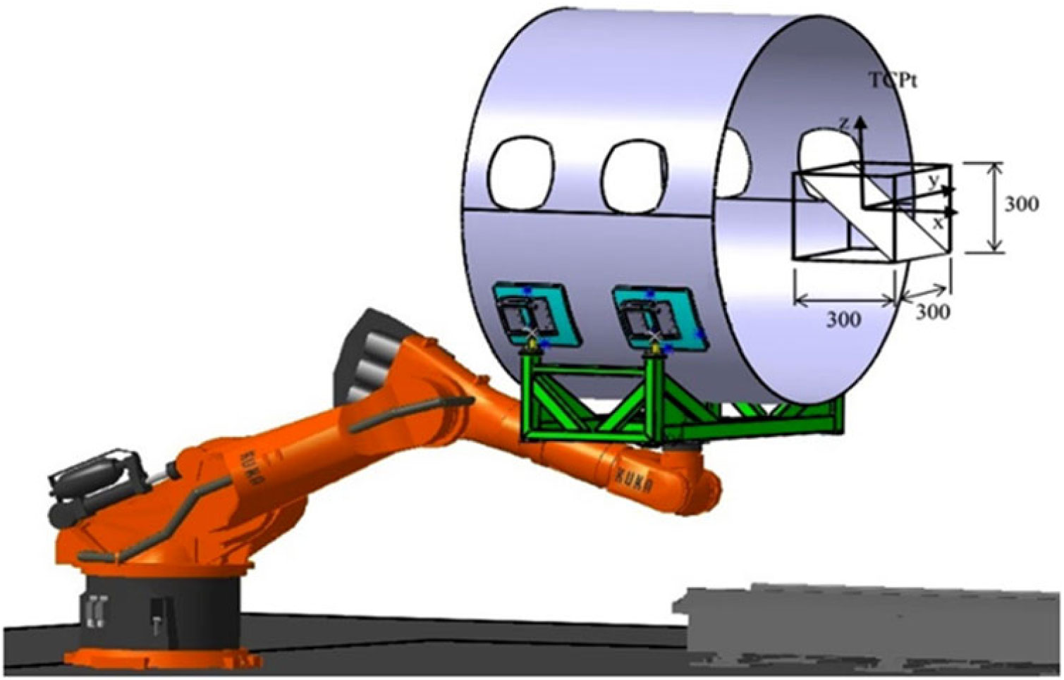
Figure 15. Cube location in the robot workspace, oblique plane.
Five measurement points,
 $P1{-}P5$
, are located on the diagonals of the measuring plane. P1 is the intersection of the diagonals and is the center of the cube. The points P2 to P5 are located at a distance from the ends of the diagonals equal to 10
$P1{-}P5$
, are located on the diagonals of the measuring plane. P1 is the intersection of the diagonals and is the center of the cube. The points P2 to P5 are located at a distance from the ends of the diagonals equal to 10
 $\pm 2 $
% of the length of the diagonal, L (see Fig. 16).
$\pm 2 $
% of the length of the diagonal, L (see Fig. 16).

Figure 16. Cube with poses P1-P5 in an oblique measuring plane. Source(Reference Amorim, Sutério and Trabasso27).
Starting from P1, the robot follows a linear pose-to-pose path moving the TCPt to all programmed poses. As depicted in Fig. 17, each of the poses is approached unidirectionally. The waiting period between the poses is set to 45 seconds. During this period, three tooling balls, which have been referenced to TCP in advance, are measured with the LR system. This method permits the determination of the actual position and orientation of the TCPt with an uncertainty of
 $\text{u} = 0.024\text{mm}\ (2\sigma)$
. To prevent the robot security breaks from causing bias during the measurements, the respective threshold is set to a time t with
$\text{u} = 0.024\text{mm}\ (2\sigma)$
. To prevent the robot security breaks from causing bias during the measurements, the respective threshold is set to a time t with
 $\textit{t}>45 \text{s}$
.
$\textit{t}>45 \text{s}$
.

Figure 17. Measurement cycles. Source(Reference Amorim, Sutério and Trabasso27).
Measurements are taken from the 1st cycle on. After n cycles, pose accuracy (
 ${AP}_{P}$
,
${AP}_{P}$
,
 ${AP}_{a}$
,
${AP}_{a}$
,
 ${AP}_{b}$
, and
${AP}_{b}$
, and
 ${AP}_{c}$
) as well as pose repeatability (
${AP}_{c}$
) as well as pose repeatability (
 ${RP}_{l}$
,
${RP}_{l}$
,
 ${RP}_{a}$
,
${RP}_{a}$
,
 ${RP}_{b}$
, and
${RP}_{b}$
, and
 ${RP}_{c}$
) are calculated for each pose separately. The nominal positions are shown in Table 2 and indicate the target poses for the robot TCP with respect to the other fuselage, a relative reference frame.
${RP}_{c}$
) are calculated for each pose separately. The nominal positions are shown in Table 2 and indicate the target poses for the robot TCP with respect to the other fuselage, a relative reference frame.
Table 2 Command poses for the KR-500/K-610 experiment

*All coordinates and angles with respect to
 $\text{F}_{major}$
6.0 RESULTS AND DISCUSSION
The measurement cycles shown in Fig. 17 were run with both open- (without the K-610 correction) and closed-loop control, with n = 30 repetitions each, a sample size recommended by the EN ISO 9283 standard. Tables 3 and 4 show the averaged values for the five different poses in direct comparison between open- and closed-loop control, respectively. The average positioning accuracy is improved by a factor of 16x, while the orientation is reduced from a maximum value of
 ${0.008}^\circ$
to
${0.008}^\circ$
to
 ${0.002}^\circ$
.
${0.002}^\circ$
.
Table 3 K-610 average accuracy for P1-P5

*Measurements taken with LR at a 2 m range. 3D measurement uncertainty u according to data sheet:
 $\text{u} = 0.024\text{mm}$
(
$\text{u} = 0.024\text{mm}$
(
 $2 \sigma $
). This fulfills EN ISO 9283 requirement
$2 \sigma $
). This fulfills EN ISO 9283 requirement
 $\sigma \leq 0$
.
$\sigma \leq 0$
.
 $25 *{AP}_{P}$
Table 4 K-610 average repeatability for P1-P5

*Measurements taken with LR at a 2 m range. 3D measurement uncertainty u according to data sheet:
 $\text{u} = 0.024\text{mm}$
(
$\text{u} = 0.024\text{mm}$
(
 $2 \sigma $
). This fulfills EN ISO 9283 requirement
$2 \sigma $
). This fulfills EN ISO 9283 requirement
 $\sigma = 0$
.
$\sigma = 0$
.
 $25 *{AP}_{P}$
The data also was analyzed under statistical considerations. A factorial model with factors ARC (levels on and off) and Pose (levels
 $P1{-}P5$
) was set up. The sample contains 300 measurements, with 30 replications for each factor combination (Table 5).
$P1{-}P5$
) was set up. The sample contains 300 measurements, with 30 replications for each factor combination (Table 5).
Table 5 Number of replications per factor level, KR-500/K-610

The response variables are the position deviation,
 $\Delta P$
, and the orientation deviation,
$\Delta P$
, and the orientation deviation,
 $\Delta O$
, calculated with Equations (7) and (8), respectively. In both equations, LR measurements are compared with the nominal values programmed in the robot.
$\Delta O$
, calculated with Equations (7) and (8), respectively. In both equations, LR measurements are compared with the nominal values programmed in the robot.
 \begin{equation}
\Delta P=\sqrt{{{(x}_{meas}-x_{norm})}^2+{{( y}_{meas}-y_{norm})}^2+{{(z}_{meas}-z_{norm})}^2}
\label{eqn7}
\end{equation}
\begin{equation}
\Delta P=\sqrt{{{(x}_{meas}-x_{norm})}^2+{{( y}_{meas}-y_{norm})}^2+{{(z}_{meas}-z_{norm})}^2}
\label{eqn7}
\end{equation}
 \begin{equation}
\Delta O=\sqrt{{{(a}_{meas}-a_{norm})}^2+{{(b}_{meas}-b_{norm})}^2+{{(c}_{meas}-c_{norm})}^2}
\label{eqn8}
\end{equation}
\begin{equation}
\Delta O=\sqrt{{{(a}_{meas}-a_{norm})}^2+{{(b}_{meas}-b_{norm})}^2+{{(c}_{meas}-c_{norm})}^2}
\label{eqn8}
\end{equation}
where meas denotes measured and nom denotes nominal, (x, y, and z) are the position components, and (a, b, and c) are the orientation components. The effects model used herein is the one presented by D C Montgomery(Reference Montgomery32).
The boxplots in Fig. 18 confirm the drastic
 $\Delta P$
improvement of the closed-loop configuration. They show that the system accuracy varies in space, an expected result due to its dependency on robot joint values. This effect is virtually eliminated in the closed-loop due to the spatial uniformity of the camera corrections.
$\Delta P$
improvement of the closed-loop configuration. They show that the system accuracy varies in space, an expected result due to its dependency on robot joint values. This effect is virtually eliminated in the closed-loop due to the spatial uniformity of the camera corrections.
 $\Delta O$
has a similar improvement from open- to closed-loop, although with a slight increase in repeatability, translated in the more spread whiskers, especially for P5.
$\Delta O$
has a similar improvement from open- to closed-loop, although with a slight increase in repeatability, translated in the more spread whiskers, especially for P5.

Figure 18. Influence of the ARC and pose factors on the position and orientation accuracies, K-610.
The residual plots (Fig. 19) also show satisfactory results for the normality and independence assumptions, confirming the model adequacy. Given the F-tests, the ANOVA in Table 6 shows that all the null hypotheses are rejected for this experiment as well; that is, all factors influence the response variable.

Figure 19. Residual plots allow for the assessment of the model adequacy, K-610.
Table 6 ANOVA for the KR-500/K-610 combination

Significant codes: 0 ‘***’ 0.001 ‘**’ 0.01 ‘*’ 0.05 ‘.’ 0.1 ‘ ’ 1
7.0 CONCLUSIONS
In recent years the aerospace industry has seen an increase in the use of automation solutions for the assembly of major components, in contrast with its automotive counterpart, which has featured automated production lines for many decades. Among other benefits are improved product quality, reduced lead time, and better ergonomics for workers. The slow yet steady replacement of the traditionally manual methods reflect two sides of the aerospace sector. First, a historical conservativeness dictates a rigorous analysis before the adoption of any prospective improvements in production methods. Second, and likely influenced by the latter, a continuous evolution in the technology of machine tools has enabled automated solutions to meet such rigorous requirements.
Yet most solutions currently available are dedicated, which translates to low flexibility and thus high cost. The aerospace industry in general and especially budget manufacturers, such as the Brazilian market, are starting to benefit from what is called lightweight automation and will increasingly do so in coming years as a feasible way to achieve higher percentages of automated production. Towards that end, the ASAA Lab has proposed an alternative solution based on available COTS components such as industrial manipulators and high-volume metrology devices.
The main contribution resulting from this research is the determination of a single value, the spatial accuracy of the chosen alignment alternative. The optimal alternative positions the fuselage section in space within 0.16mm and
 ${0.004}^\circ$
. This metric, although simple, measurement validates all the preceding development work. It is within the process requirements and near ten times better than the performance of standard manipulators. Still, the cost of this solution is at only a fraction of the cost of more traditional alternatives. The results of this work should prove helpful to the aerospace industry by providing an added dimension in the selection of automated solutions for fuselage alignment.
${0.004}^\circ$
. This metric, although simple, measurement validates all the preceding development work. It is within the process requirements and near ten times better than the performance of standard manipulators. Still, the cost of this solution is at only a fraction of the cost of more traditional alternatives. The results of this work should prove helpful to the aerospace industry by providing an added dimension in the selection of automated solutions for fuselage alignment.
Future work should include the integration of the K-610 and LR sensors into a unique interface for ease of use. The incorporation of other functionalities such as environmental monitoring would prepare the ASAA cell for an eventual industry deployment, and a Failure Mode Effects Analysis could help identify bugs and increase its robustness. A study of its lead time characteristics and complete cost analysis would help assess its commercial viability.
ACKNOWLEDGEMENTS
The authors would like to thank Financiadora de Estudos e Projetos (FINEP), Fundação de Amparo à Pesquisa do Estado de São Paulo (FAPESP) and Conselho Nacional de Desenvolvimento Cientfico e Tecnológico (CNPq) for financial support, Nikon Metrology and KUKA for product support, and Embraer S/A for the support received for this project on visits to their premises.


