NOMENCLATURE
- aG
-
acceleration vector of G
-
 $\bar{c}_e$
-
average chord of the elevator
- C (he )
-
hinge moment coefficient
- CLmax
-
maximum lift curve slope
- ee
-
distance between the control surface mass centres and the corresponding hinge axis
- F e, C
-
force applied by the pilot to the stick
- gz
-
component of the vertical acceleration vector
- G
-
mass centre
- H e, A
-
hinge moment (aerodynamic action)
- H e, C
-
control hinge moment
- HInertial
-
inertial moment resulting from the inertial coupling action
- Ie
-
moment of inertia of elevator
- J
-
Jacobian matrix
- me
-
control surface mass
- nz
-
load factor
-
$\bar{q}$
-
local dynamic pressure
- R
-
gear ratio
- S
-
aircraft area
- Se
-
elevator area
- VG
-
velocity vector of G
-
$\ddot{\delta }_e$
-
moving surface acceleration
-
$\vec{\Omega }$
-
angular rate vector
- η H
-
form coefficient
- τ
-
actuator torque


1.0 INTRODUCTION
In the last few decades, the use of driving simulation for traffic safety, vehicle design and driver perception studies have expanded rapidly(Reference Hoedemaeker and Brookhuis1-Reference Katzourakis, de Winter, de Groot and Happee3). This is largely because simulation saves engineering time and costs, and can be used for studies of road and traffic safety. In addition, recent psychophysical studies have revealed an unexpectedly important contribution of vestibular and force cues in distance perception and steering, prompting a re-evaluation of the role of visuo-vestibular and visuo-haptics interactions in driving simulation studies.
Simulation is also a useful and indispensable tool for aviation research and training. It has evolved and matured over the last 40 years in equal pace with developments in the aerospace industry. Flight simulation allows pilots to fly in simulated conditions, without the costs and safety issues that go with performing real flight. When flight simulation and research are combined, the objective is to measure the human performance in the simulated environment(Reference Clari, Ruigrok, Heesbeen and Groeneweg4). Research will pose certain requirements on the use of simulation hardware and software. It requires generic tools that can be adjusted to the evolving insight in topics. This implies that flight simulators (hardware) and simulation models (software) used for research will often be a trade-off between realism and flexibility(Reference Hoekstra5). Therefore, a flight simulator must include an aircraft model, a display capability and control hardware(Reference Teufel, Nusseck, Beykirch, Butler, Kerger and Blthoff6). The aircraft model is implemented as software(Reference Holzapfel, Sturhan and Sachs7). Three examples of commonly used flight simulator packages are Microsoft Flight Simulator (sometimes abbreviated to MSFS or FS), FlightGear and XPlane.
The flight controls are hardware providing input to the aircraft model. In most cases, they are used along with an aircraft-like control input such as a joystick, yoke or rudder pedals.
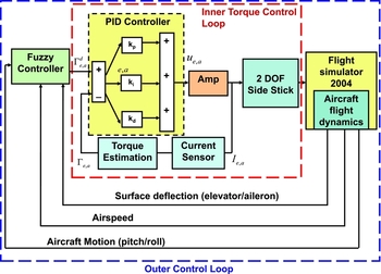
The interaction between the pilot and the flight control system is one of the subjects of concern. In manual control of the aircraft, the side-stick is the primary input device to the flight control system. Therefore, in the conventional control systems, the stick force and stick displacement have a direct relation to the control surface hinge moments, and deflections under stability requirements(Reference Albert, Rehmann and Mitman8). However, in a modern aircraft, the mechanical linkage between the control systems and the control surfaces is removed. The side-stick usually provides the pilot only with an impression of the input to the flight control system, based on force-feeling program implemented on the Control Loading System (CLS) (Fig. 1). In a typical aircraft, the force-feeling relation may change with the flight condition, and it may be desirable to simulator failure cases for pilot training. Mueller(Reference Mueller9) described the evolution of the pilot force program, from its beginning with the use of analog computers, to the successful digital computer replacement, which provided a significant improvement in responding to customer requirements.

Figure 1. Control loop with a servo-controlled side-stick.
However, the idea of force-feedback integration into flight simulators is not new; force feedback is considerably taken into account in almost all professional flight simulators. It is one of the requirements for flight simulator certification. It helps to take into account the aerodynamic forces applied to the aircraft. This sensation is inherent of our proprioceptive sensory system and can also complement sensory modalities such as vision. However, it has not been extensively investigated in-flight simulation in comparison to other simulation fields. A state of the art on force feedback shows that it is especially used in virtual prototyping and surgery simulation fields. Its role is of special interest because it is used in important decision-making scenarios such as the discrimination of healthy versus abnormal tissues and identification of organs and allows to commit appropriate force control actions for safe tissue manipulation(Reference Puangmali, Althoefer, Seneviratne, Murphy and Dasgupta10).
In Ref. Reference Alaimo, Pollini, Magazz, Bresciani, Giordano, Innocenti and Bulthoff11, force feedback has been used to remotely pilot Unmanned Aerial Vehicles (UAV) using a force-feedback interface for collision avoidance and time delay teleoperation in Ref. Reference Lam, Mulder and Van Paassen12. In Ref. Reference Nam and Hong13, the authors have developed an active stick controller using a combined position and force control strategy with friction compensation. A similar force-feedback stick has been developed in Ref. Reference Lin and Young14 for general use. Some applications of such a stick are motivated by the development of control loading mechanisms for flight motion simulation(Reference Baarspul15). In order to achieve a wide range of feeling, electric actuators are used with a programmable control system linked to the simulator host computer. In this way, the main simulation of the aircraft and the instructor can interact with the system to change its feeling. For example, in Ref. Reference Coiro, De Marco and Nicolosi16, the authors proposed to enhance the realism in piloting efforts. Particular care has been taken to implement hinge moment equations in the simulation software. The result is a closed-loop force-feedback system on all aircraft commands. Two useful and noteworthy generalisations have been implemented in this context: the effect of the mechanical linkage dynamics on the control surface motion and the effects on the control displacement due to the mechanical friction and to the presence of springs. The geometric, mass, inertia characteristics of each control surface and the hinge moment coefficients are managed by the control loading software. While the authors in Ref. Reference Alaimo, Pollini, Magazz, Bresciani, Giordano, Innocenti and Bulthoff11 proposed an aerodynamically inspired force-feedback law named ‘Conventional Aircraft Artificial Feel’ that was implemented as a variable stiffness spring based on the aerodynamics characteristics of the aircraft, the current state of the aircraft (speed, angle-of-attack, etc.) and of course from stick deflection. Another example is the work proposed in Ref. Reference Condomines, Defay and Alazard17 where the authors propose to control in real time the mechanical impedance of the stick in order to adapt its apparent inertial, stiffness and damping. Such a closed-loop force-controlled device will allow to adjust the impedance to the morphology of the pilot or to the wish of the pilot or the company and to give some kinesthetic sensations to the pilot in order to inform him on the operational state of the aircraft.
The aim of this work is to develop a new control interface to be used in a research flight simulator(Reference Guiatni, Ournid, Boulahlib and Abane18). The advantage of such an interface is that the stick force and stick displacement can be made independent. This yields the possibility of influencing the subject’s output generation by changing the dynamic relation between stick force, stick displacement, the aircraft’s motion and aerodynamic data. This control interface will be used to control the pitch and the roll motions of a simulated aircraft and at the same time to reproduce the force feedback onto the pilot hand.
In order to avoid the use of complex aerodynamic equations which need in-depth knowledge in aerodynamics, we propose to use a Fuzzy Logic Controller (FLC), which is based only on a pilot’s knowledge and experience. To our best knowledge, this work is the first to propose the integration of fuzzy logic force controller in flight simulation for creating force feedback. The FLC is used to generate torques/forces command to the inner torque control loop based on the aerodynamic feedback data provided by the MSFS program. The use of advanced and intelligent control techniques is common in the aeronautics field in order to overcome the model’s complexity and the lack of parameters and to avoid time-consuming procedures. In Refs Reference Grigorie, Botez, Popov, Mamou and Mebarki19 and Reference Grigorie, Botez, Mamou and Mebarki20, a hybrid fuzzy logic PID plus conventional on-off controller have been used in the actuation of a morphing wing. A combination of guardian maps, genetic algorithms and Linear-Quadratic-Gaussian (LQR) theories have been used in Ref. Reference Ghazi and Botez21 for the control of the Lynx helicopter and Cessna Citation X aircraft, whereas in Ref. Reference Grigorie, Botez, Popov, Mamou and Mebarki22, adaptive neuro-fuzzy controllers were designed for an open-loop morphing wing system. Authors in Ref. Reference Boughari, Botez, Ghazi and Theel23 propose a flight control system to achieve good performance with acceptable flying quality within the specified flight envelope while ensuring robustness for model variations, such as mass variation due to fuel burn for the Cessna Citation X aircraft. The controller was designed using the H-infinity method and optimised using both genetic and differential evolution algorithms.
This paper is organised as follows: Section 2 gives a background about the evolution of the flight control systems and introduces the role of the force feedback. Section 3.1 presents a brief model of the longitudinal control dynamics related to the pilot’s action on the stick. Section 4 presents the MSFS software which is used to perform the simulation. Section 5 develops the design, instrumentation and control of the two DOF stick, which provides force feedback around the roll and pitch axes. In Section 7, we present the design of fuzzy controllers, which calculate the force to be generated on the stick. Finally, we present the implementation details and some results about the fuzzy logic-based force-feedback flight simulation.
2.0 BACKGROUND
Conventional aircraft with mechanical linkages have control stick forces that increase with aircraft speed. This is because aerodynamic forces increase with speed, making the control surfaces more difficult to move. This is beneficial to piloting characteristics because the force applied to the stick is about the same for the same rate of manoeuvre or normal acceleration. The pilot can, therefore, feel the forces and rate of manoeuvre. In addition, it is often the case that as the aircraft approaches flight limits such as stall, an aerodynamic buffering occurs, which is felt by the pilot by a mild shaking of the stick.
With the development of the electrical flight control systems using fly-by-wire technology, the traditional mechanical linkages between the cockpit controls and the aircraft’s control surfaces have been eliminated. They were replaced by control computers and actuators, thus reducing both weight and maintenance of the aircraft while improving performance and safety. The flight control system protects the aircraft from stalling, over-speeding, excessive attitudes and even wind-shear.
In fly-by-wire aircraft, the control stick indirectly controls the movement of the control surfaces. Passive sticks cannot change their feel characteristics with flight condition, so the pilot has fewer cues to make him aware of the flight condition than in a conventional aircraft with mechanical linkages.
Whalley and Achache(Reference Whalley and Achache24) reported that force cueing provided by the flight control system is an effective means of signalling the pilot of an impending flight stability exceedance. Force cues via the control inputs are immediate and unambiguous, and they require no interpretation as to what control response is required to remedy the situation.
The active stick gives flexibility to include additional feel characteristics (cues) that can improve the piloting characteristics since it is driven by actuators that can be programmed to affect the force and displacement characteristics felt by the pilot. This is very different to conventional fly-by-wire aircraft control sticks, which are passive. By using actuators to control the movement of the active stick in response to force applied by the pilot, the stick can be programmed to feel as though it is held by springs and dampers. The characteristics of a synthetic spring feel can vary dramatically with the flight condition, thus allowing the pilot to feel how the aerodynamic forces are changing, and therefore give the pilot tactile cues of the flight restrictions and the onset of structural limitations including the flight envelope protection such as bank angle protection, turn compensation, stall and over-speed protection, and pitch control and stability augmentation. As the aircraft approaches flight limits, this is felt by the pilot by a mild shaking of the stick or a big force that keep the aircraft within the flight envelope.
The ability to feel the physical cues of flight improves the pilot’s situational awareness, decreases pilot workload, and ultimately enhances safety. Sophisticated artificial feels are the so-called Q and QN feel. The Q feel system receives data from the pitot-static probes, reading the dynamic pressure, that is proportional to the aircraft speed through the air density. In the QN feel, force is generated proportionally to both dynamic pressure and load factor. These signals are used to modify the stiffness in the artificial feel system in such a way that the pilot is given a contrast force in the stick.
The stiffness and damping effects are usually produced using hydraulic or electrical actuators. However, the control force quality is an important factor which determines the level of sophistication and fidelity of a flight simulator. Different levels of fidelity characteristics can be found in this later: the control system can be free force feeling, with constant force (spring/damper), partial duplication of actual force or complete duplication of this later(Reference Albert, Rehmann and Mitman8).
This makes the force-feedback system one of the essential subsystems of flight simulator. Its main function is to provide force feeling of loading for simulator, simulate the real feeling of navigating for the pilot, and provide corresponding force according to the simulated condition for navigating.
3.0 FORCE FEEDBACK IN CONVENTIONAL AIRCRAFT
3.1 Traditional mechanical linkages modelling
To illustrate the analysis of stick force, hinge moment, etc., consider the reversible control system (no power assist) shown in Fig. 2 which presents the mechanical linkage of the control system, and assume that the aircraft is flying at a low subsonic speed (Mach number effects negligible in the aerodynamics). For simplification purpose, we will present here the well-known equation of motion of a conventional elevator, including the inertial coupling and hinge line eccentricity effects(Reference Coiro, De Marco and Nicolosi16,Reference Coiro, De Marco and Nicolosi25) . The model of longitudinal control dynamics is illustrated in Fig. 3.
 $$\begin{equation}
I_e \ddot{\delta }_e - H_{Inertial} = H_{e,A} + H_{e,C},
\end{equation}$$
$$\begin{equation}
I_e \ddot{\delta }_e - H_{Inertial} = H_{e,A} + H_{e,C},
\end{equation}$$
where:
 $$\begin{equation}
H_{Inertial} = \left( {\dot{q} - pr} \right)I_{ey} - \left( {a_{G_z } - g_z } \right)m_e e_e,
\end{equation}$$
$$\begin{equation}
H_{Inertial} = \left( {\dot{q} - pr} \right)I_{ey} - \left( {a_{G_z } - g_z } \right)m_e e_e,
\end{equation}$$
 $$\begin{equation}
H_{e,A} = \eta _H \bar{q} S_e c_e C_{h_e },
\end{equation}$$
$$\begin{equation}
H_{e,A} = \eta _H \bar{q} S_e c_e C_{h_e },
\end{equation}$$
 $$\begin{equation}
H_{e,C} = F_{e,C} /R
\end{equation}$$
$$\begin{equation}
H_{e,C} = F_{e,C} /R
\end{equation}$$
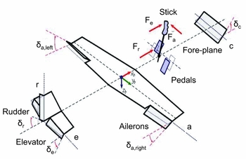
Figure 2. Sign conventions in the dynamic models of the aerodynamic surfaces. A European convention is adopted for stick forces(Reference Coiro, De Marco and Nicolosi25).

Figure 3. Schematic of longitudinal control loading(Reference Coiro, De Marco and Nicolosi25).
The first term in Equation (1) is the typical inertial term which results from the multiplication of the moving surface angular acceleration
 $\ddot{\delta }_e$
and its moment of inertia Ie
around the hinge line. The remaining terms are all torques acting on the elevator around the hinge as well. The term HInertial
represents the moment resulting from the inertial coupling actions (time-varying aircraft pitch rate and/or combination of non-zero roll and yaw rates about aircraft centre of gravity). The quantity a
Gz
is the component onto the standard body-fixed axis zb
of the acceleration vector
$\ddot{\delta }_e$
and its moment of inertia Ie
around the hinge line. The remaining terms are all torques acting on the elevator around the hinge as well. The term HInertial
represents the moment resulting from the inertial coupling actions (time-varying aircraft pitch rate and/or combination of non-zero roll and yaw rates about aircraft centre of gravity). The quantity a
Gz
is the component onto the standard body-fixed axis zb
of the acceleration vector
 $\vec{a}_G$
, acceleration of the aircraft’s mass centre G. The acceleration vector is given as a function of the velocity by the classical derivation formula:
$\vec{a}_G$
, acceleration of the aircraft’s mass centre G. The acceleration vector is given as a function of the velocity by the classical derivation formula:
 $$\begin{equation}
\vec{a}_G = \frac{{d\vec{V}_G }}{{dt}} + \vec{\Omega }\times \vec{V}_G,
\end{equation}$$
$$\begin{equation}
\vec{a}_G = \frac{{d\vec{V}_G }}{{dt}} + \vec{\Omega }\times \vec{V}_G,
\end{equation}$$
with
 $\vec{V_G}$
the velocity vector of G and
$\vec{V_G}$
the velocity vector of G and
 $\vec{\Omega }$
the instantaneous angular rate vector of the aircraft carried frame with respect to a fixed frame. When expressed in terms of scalar components in the body frame, the acceleration component is given by:
$\vec{\Omega }$
the instantaneous angular rate vector of the aircraft carried frame with respect to a fixed frame. When expressed in terms of scalar components in the body frame, the acceleration component is given by:
 $$\begin{equation}
a_{G_z } = \dot{w} + \left( {v p - u q} \right),
\end{equation}$$
$$\begin{equation}
a_{G_z } = \dot{w} + \left( {v p - u q} \right),
\end{equation}$$
where u, w and v are the components of
 $\vec{V_G}$
onto the body-fixed axes, and p, q and r are the components of
$\vec{V_G}$
onto the body-fixed axes, and p, q and r are the components of
 $\vec{\Omega }$
. The quantity gz
is the z-component of the vertical acceleration vector on the aircraft body frame. The eccentricity ee
is the distance between the control surface mass centre, Ge
, and the corresponding hinge axis, as shown in Fig. 3. It results in an inertial moment about the hinge when multiplied by the control surface mass me
and by the relevant component of the aircraft mass centre acceleration (a
Gy
− gy
). When the mass centre Ge
is projected onto the respective hinge axis, the point Ce
is obtained.
$\vec{\Omega }$
. The quantity gz
is the z-component of the vertical acceleration vector on the aircraft body frame. The eccentricity ee
is the distance between the control surface mass centre, Ge
, and the corresponding hinge axis, as shown in Fig. 3. It results in an inertial moment about the hinge when multiplied by the control surface mass me
and by the relevant component of the aircraft mass centre acceleration (a
Gy
− gy
). When the mass centre Ge
is projected onto the respective hinge axis, the point Ce
is obtained.
Iey
represents the product of inertia of the elevator with respect to the elevator hinge axis e and the aircraft body axis yb
. The term H
e, A
is the moment resulting from aerodynamic actions on the elevator, where
 $\bar{q}$
is the local dynamic pressure.
$\bar{q}$
is the local dynamic pressure.
 $$\begin{equation}
\bar{q} = (1/2) \rho V^2
\end{equation}$$
$$\begin{equation}
\bar{q} = (1/2) \rho V^2
\end{equation}$$
ρ is the air density, V is the airspeed, Se
is the elevator area aft of the hinge line,
 $\bar{c}_e$
is the average chord of the elevator aft of the chord line and η
H
is a form coefficient.
$\bar{c}_e$
is the average chord of the elevator aft of the chord line and η
H
is a form coefficient.
Finally, the action of the pilot is the control hinge moment H e, C . F e, C is the force applied by the pilot to the yoke. It is reduced to a moment about the elevator hinge after dividing by the dimensional gearing ratio R. In a stick-free condition, this term is zero. Usually, in a commanded manoeuvre, the pilot control force F e, C is non-zero(Reference Coiro, De Marco and Nicolosi25).
Figure 4 shows the conventionally positive moments acting on a couple of traditional elevators, whose motion is a rotation about the respective hinge. The aerodynamic action is the hinge moment H e, A . Inertial actions consist in:
-
• The moment
$I_e \ddot{\delta }_e$
due to the accelerated elevator rotation about the hinge,
Figure 4. Schematic of the actions acting on the elevator(Reference Coiro, De Marco and Nicolosi25).
-
• The moment (a Gz − gz )meee , due to the elevator’s eccentricity.


If the pilot’s action is adequate to react to the feedback and is able to keep the control position stationary (see Fig. 4), the flight conditions remain stick-fixed, or nearly so. If not, the unbalance between the force actually exerted on the control and the one calculated by the force-feedback system from simulated flight data results in a general manoeuvred flight with a varying excursion of one or possibly all aerodynamic control surfaces(Reference Coiro, De Marco and Nicolosi25).
3.2 Flight envelope
Flight regime of any aircraft includes all permissible combinations of speeds, altitudes, weights, centres of gravity and configurations. This regime is shaped by the aerodynamics, propulsion, structure and dynamics of the aircraft. The borders of this flight regime are called flight envelope or manoeuvring envelope(Reference Sadraey26). This envelope demonstrates the variations of airspeed versus load factor (V − n). This later is defined as the ratio of the lift to the weight of the aircraft. In other words, it depicts the aircraft limit load factor as a function of airspeed(Reference Falkena, Borst and Mulder27). The load factor nz is defined as follows:
 $$\begin{equation}
n_z = \bar{q}.S.C_{Lmax} /mg,
\end{equation}$$
$$\begin{equation}
n_z = \bar{q}.S.C_{Lmax} /mg,
\end{equation}$$
where mg is the weight of the aircraft, CLmax represents the maximum lift curve slope, and S represents the aircraft area. Pilots are trained to monitor cockpit instruments and follow safety guidelines for envelope protection. Experienced pilots also rely on secondary vehicle cues, such as structural vibration, while operating close to the edges of the flight envelope.
4.0 DATA EXTRACTION FROM MICROSOFT FLIGHT SIMULATOR (MSFS)
4.1 MSFS features
The use of non-flight-certified Commercial-off-the-Shelf (COTS) solutions has proved its fidelity and coordination characters as a flight training device(Reference Zheng, Zheng and Han28). MSFS is a flight simulator program that is marketed and often seen as a video game. However, it is less a game than an immersive virtual environment, as it is very realistic. Its first version appeared in 1982, whereas its most recent versions, Century of Flight and Flight Simulator X, appeared in 2003 and 2006, respectively(29).
We have chosen to use Flight Simulator 2004 for many reasons. First, this flight simulator is commercially available at a relatively low cost. MSFS is used by the US Navy and the Flight Safety International Academy (US) to teach theirs trainee pilots. Despite its good realism provided by a very good three-dimensional displaying and dynamic aircraft models, MSFS is not very greedy of computation power. In addition, the long history, the consistent popularity and the open nature of flight simulator structure have encouraged a very large body of freeware and payware add-on packages to be developed. These add-ons, widely available over the Internet, are very helpful because they not only permit the user to change internal aspects of the simulator (aircrafts, scenery) but also to interface it with external software and hardware, such as home-built cockpits. Among the most famous add-ons, we cite:
-
• FSUIPC (can interface with MSFS, see Section 4.2),
-
• WideFS (a package that enable users to run MSFS applications on computers connected via TCP-IP network to a server that runs MSFS),
-
• WidevieW (a set of special gauges which can be installed in any aircraft’s panel and that can be used to create virtual cockpits with multiple outside views, using networked PCs),
-
• FS-Interrogate (a tool that provide a list of data that can be reached through FSUIPC).
4.2 Communication with MSFS
We extract/send data from/to MSFS 2004 using a dynamic link library add-on made by Pete Dowson(Reference Dowson30) called Flight Simulator Universal Inter-Process Communication (FSUIPC) (see Fig. 5). FSUIPC was developed to succeed to FS6IPC, which was developed by Adam Szofran to interface to FS95. Both modules are designed to allow external (i.e. separate) programs to communicate with and control MSFS in real time. In other words, they permit to read from and write in MSFS while it is running and place it in a 64 Kb buffer. Therefore, to achieve a variable, we only have to know its offset (address) in this buffer. However, before writing or reading data from FSUIPC, we have to scale it to the desirable unit.

Figure 5. Data flow from/to MSFS 2004.
In our manipulation, we have extracted the deflection angles (of the aileron and the elevator), the pitch, the roll angles and the airspeed of the simulated aircraft in the MSFS environment, in real-time using a software based on the Software Developement Kit (SDK) and FSUIPC. The read-send process is cadenced using a basic software timer that allows to get at a sampling frequency of 1KHz.
5.0 FORCE-FEEDBACK SIDE-STICK DESIGN
5.1 Design considerations
The mechanical constraints for a force-feedback device include low inertia, back-drivability, no backlash, lightweight and negligible friction(Reference Laycock and Day31). Obtaining negligible friction and inertia can be a problem particularly when high stiffness is required. High stiffness implies a stiff mechanical interface, which needs to be constructed from linkages and joints which increase the friction and the overall weight of the device(Reference Laycock and Day31,Reference Baser, Konukseven and Koku32) . Therefore, the materials used to construct such devices need to be chosen by taking into account the previously presented requirements.
When considering the construction of a force-feedback device, there is a choice between serial and parallel mechanisms. The key difference between serial mechanisms and parallel mechanisms is in their kinematic structures. Parallel mechanisms are composed of at least two closed chains which connect a moving platform to a fixed base that permits the location of the actuator to be away from the moving platform. A serial mechanism presents larger workspace volume than a parallel mechanism(Reference Li33). For a parallel mechanism, workspace must be compromised due to constraints of all links that connect the end-effector. For a serial mechanism, every actuator has to exert enough torque and power to move all distal links and overhead actuators. However, the actuators of a parallel mechanism can be placed on ground to support stronger payload than serial mechanism.
For a parallel mechanism, the geometrical errors are not accumulated, as all the branches are connected to the end-effector. The dimension accuracy of each link must be high so that the position and orientation of the end effector is more accurate than the serial mechanism. For a serial mechanism, the geometrical errors accumulate the error of each link. Therefore, the end effector will have lower position accuracy(Reference Li33). For a serial mechanism(Reference Laycock and Day31), each chain increases the total inertia while it decreases the total stiffness. Parallel mechanisms do not exhibit the above problem and have a much higher stiffness(Reference Birglen, Gosselin and Pouliot34).
Our design (see Fig. 6) is a 2DOF parallel mechanism which insures the movement around pitch and roll axes. This parallel mechanism consists of two legs (chains), each being regarded separately as a serial manipulator. The two chains have an arc shape with a groove which allows a translation movement for the handle.

Figure 6. The Computer Aided Design (CAD) model of the force-feedback side-stick.
Actuators provide force for the device. The type of the incorporated actuators is an important issue that affects the overall weight of the device(Reference Guiatni, Riboulet and Kheddar35). In most cases, a good actuator should be compact and light as well as able to produce the necessary power to deliver the necessary force feedback.
5.2 Actuation, transmission and reduction
Actuation, reduction and transmission are closely coupled and must be designed together. They are selected according to the requirements specified above. There are trade-offs between power, volume and weight because actuators capable of producing large forces are generally heavier and are larger in size than those actuators capable of smaller forces. In order to select the required actuators, we have applied maximal forces on the stick’s handle under MotionWorks plug-in of Solidworks software. As a result, this later provides us with the necessary actuators torques which can counteract the applied forces. We select brushed Maxon RE25 DC motors with a low inertia and low friction(Reference Guiatni, Riboulet and Kheddar35,Reference Tavakoli, Patel and Moallem36) , which are suitable for force-feedback devices.
In order to provide the highest amount of fidelity, direct drive (absence of transmission of reduction) is likely to be the best solution. However, this solution does not provide the adequate forces/torques needed for our application, which we saw earlier is critical. Among the other transmission and reduction techniques such as the use of linkages, cables, steel belts, shafts plus gears, this last one gives the worst case because it causes high backlash and high back-drive friction due to the gear gaps and gear friction(Reference Hayward37,Reference Hayward and Astley38) . Back-drive friction and backlash can be reduced by using cable-driven transmission systems (see Fig. 7).

Figure 7. Force sensing and torque calibration based on four strain gauges.
A solution consists of using a combined reduction (planetary gear/capstan) in order to increase the torques developed by the actuators. We use planetary gears reduction because it has fewer backlashes and less friction, especially when the reduction ratio is small (the reduction ratio is 19 in this case while it is 4 for the capstan), so that the output torques are multiplied by a factor of 76 (see Fig. 6). This means a nominal torque of about 2.25 NM.
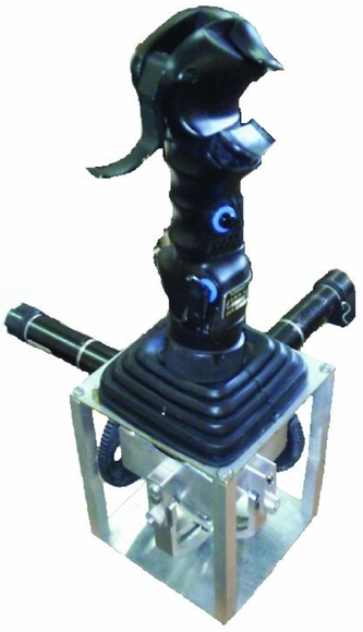
The assembled device is shown in Fig. 8. A compromise has been reached between the various design goals as follows:
-
• Aluminum was used to minimise the deflection due to the stiffness of the linkages. Links shape, thickness and stress analysis are carried out using the COSMOSXpress plug-in of SOLIDWORKS. Static analysis of the mechanical design would be sufficient because the stick will be used with low speed. The links shape and weights are computed for aluminum with a Young modulus of 69,000 MPa and a mass density of 2,700
$\text{kg}/\text{m}^{3}$
as construction material. This material is used because of its high yield strength over weight ratio(Reference Kabadayi39). In this analysis, tool-tip deformation in the translational movement direction is studied under static loading of 50 N, which correspond the maximum force which shall be generated by the actuators. The shape and thickness of the links are optimised to obtain a minimum deflection values.
Figure 8. The assembled force-feedback side-stick.
-
• The cable-driven transmission technique was used in order to overcome backlash deflection.
-
• Stainless steel ball bearings and high-precision manufacturing methods were used in order to overcome joint deflections.

The workspace boundaries of the developed stick are [ − 28, +28]°, and angular positions are measured with a resolution of 0.01°.
6.0 FORCE/TORQUE SENSING AND CONTROL
6.1 Force sensing
The most popular electrical elements used in force measurements include the resistance strain gauge, the semi-conductor strain gauge, and piezo-electric transducers. The strain gauge measures force indirectly by measuring the deflection it produces in a calibrated carrier. In our experiment, four strain gauges (type 120LY13 from Hottinger Baldwin Messtechnik (HBM)) are used to measure the deflection of the handle, two on the top side, and two on the bottom side glued to a cantilever beam (see Fig. 7). Precise alignment was maintained to prevent bending moments which can severely degrade the accuracy of the measurements. The gauges are connected in a Wheatstone bridge configuration which gives maximum sensitivity and is inherently linear. This configuration also offers first-order correction for temperature drift in the individual strain gauges. In addition, the differential placement of the gauges guaranties the independence between the measured force and the tip of its application.
6.2 Torque calculation principle
The actuator torque Γ is usually estimated based on the actuator current consumption because the actuator torque is directly proportional to motor current I as follows:
 $$\begin{equation}
\Gamma =K_{\Gamma } I,
\end{equation}$$
$$\begin{equation}
\Gamma =K_{\Gamma } I,
\end{equation}$$
where K Γ is the torque constant of the DC motor. Based on the Jacobian matrix J of the mechanism, we deduce the force F from the actuator torque.
 $$\begin{equation}
F=(J^T)^{-1}\Gamma
\end{equation}$$
$$\begin{equation}
F=(J^T)^{-1}\Gamma
\end{equation}$$
However, Equation (9) is imprecise because it does not take into account the complexity of the reduction mechanism, friction and backlash which contribute to loss of torque from the motor to the link. The results presented in Ref. Reference Walker and Salisbury40 show that such a low-cost approach performs just as well as highly accurate torque sensors when they are well calibrated, i.e. the relation between the actuator current and the ouput torque is determined experimentally.
6.3 Signal conditioning electronics and calibration
Strain gauges are low-impedance devices; they require significant excitation power to obtain reasonable levels of output voltage. We have carried out an electronics unit which convert the small mv changes in Wheatstone bridge output to a range of [ − 10, +10]V, which is proportional to the applied load or tension. The linear relation between the applied force and the output voltage is determined by calibration using troy weights.
In order to get an accurate calculation of the torque, we perform calibration experiments in two steps. In the first set of experiments, the objective is to determine the relationship between the actuator current and the current sensors output voltage. Currents are measured thanks to Hall Effect sensors (type LF306-S from LEM Transducer), which offer high-frequency responses (100 KHz). Since the Hall voltage is a low-level signal, we have carried out an amplifier with low noise, high-input impedance and moderate gain.
Then, the second set of experiments tries to find the relationship between the actuator current and output torque (see Figs 9 and 10. In this experiment, we have maintained the stick in a fixed position, and then we have applied different currents’ values. The resulted force on the handle was measured thanks to the strain gauges subsystem.

Figure 9. Current calibration (top) and torque estimation (bottom) for the pitch axis.

Figure 10. Current calibration (top) and torque estimation (bottom) for the roll axis.
Figures 9 and 10 show that the relation between the measured current and the output voltage is linear for all sensors. When comparing the estimated torques based on Equation (9) with the real torques, one can remark on the existed divergence. This is probably due to the complexity of the reduction mechanism, inertia and possible existing friction. Therefore, in our experiments, torques will be estimated based on the linear fitting equation determined by calibration.
6.4 Electronics interface and control loop
A demonstration experiment consists in the use of the MSFS software for scenery visualisation of the Cessna C172SP Skyhawk type aircraft and a 2DOF stick for its control. The control set-up consists in a Quanser’s Q8 Hardware-in-the-Loop (HIL) Control Board, which is a versatile and powerful real-time measurement and control board. The power stage is designed based on two OPA548 operational power amplifiers from Burr-Brown, which are able to provide a current about 3A. The angular positions of the active joints are measured thanks to incremental encoders type HEDS 5540.
6.5 Inner torque control loop design
The objective of the inner loop controller of the force-feedback system is to reproduce desired torques according to the torque/force commands. In this experiment, the stick handle is maintained in a fixed position. The actuators current is measured using current sensors and then converted into torque using the fitting equations established in Section 6.3. We have implemented proportional, integral, derivative (PID) controllers to achieve this objective. The ideal continuous PID controller is defined as follows:
 $$\begin{equation}
u_{r,p} \left( t \right) = k_p \varepsilon _{r,p} \left( t \right) + k_i \int _0^t {\varepsilon _{r,p} \left( \tau \right)} d\tau + k_d \frac{{d\varepsilon _{r,p} \left( t \right)}}{{dt}}
\end{equation}$$
$$\begin{equation}
u_{r,p} \left( t \right) = k_p \varepsilon _{r,p} \left( t \right) + k_i \int _0^t {\varepsilon _{r,p} \left( \tau \right)} d\tau + k_d \frac{{d\varepsilon _{r,p} \left( t \right)}}{{dt}}
\end{equation}$$
It returns the controller output u r, p ; the constants kp, ki and kd are the proportional gain, integral gain and derivative gain, respectively; ε r, p (t) = Γ d r, p (t) − Γ r, p (t) is the error between the reference torque Γ d r, p (t) and the output torque Γ r, p (t). Subscribes r and p denote for the roll and pitch axis, respectively (see Fig. 14). The first step in the design strategy is to install and tune the PID controllers. PID controllers may be tuned in a variety of ways, including hand-tuning, Ziegler-Nichols tuning, loop shaping, analytical methods, by optimisation, pole placement, or autotuning(Reference Smith41,Reference Astrom and Hagglund42) . In our project, the parameters of the PID controllers are tuned experimentally (hand-tuning) following the procedure adapted from(Reference Smith41). These parameters are selected to keep the system stable (without over-shooting in the transient phase), eliminate the steady-state error and reduce the response time (see Fig. 11, where a square torque is desired).
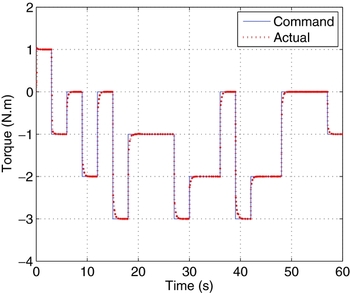
Figure 11. Torque control example: the blue line represents the desired torque, while the red line represents the obtained one.
6.6 Control loading system approximation
In order to evaluate the ability of the designed controller to reproduce accurate force programs, we have simulated a control loading system as presented in Ref. Reference Mueller9. Figure 12 illustrates the force versus position graph of force functions that are implemented in the Pilot Force Program. Details about the force program can be found in Ref. Reference Mueller9. Figure 13 shows the advantage of the controller is its flexibility to insure force feedback based on any elaborated program.

Figure 12. Pilot force example plot(Reference Mueller9).

Figure 13. Control loading system approximation.
7.0 FUZZY LOGIC CONTROLLER DESIGN
Fuzzy controllers represent an ever-growing area in controller design because they allow for ‘intelligent’ control of a system. A state of the art on design of model-based fuzzy control systems and analysis has been published in Refs 43 and 44 and more recently in Ref. Reference Precup and Hellendoorn45. Attention was also paid to the role of fuzzy systems in higher levels of the control hierarchy, such as expert control, supervision and diagnostic systems. Fuzzy logic, as defined by Yen and Langari(Reference Yen and Langari46), refers to all of the theories and technologies that employ fuzzy sets and fuzzy classes with unsharp boundaries. Fuzzy logic, as opposed to crisp logic, allows for a more lenient method of evaluating a true or false situation by implementing weighted values, fuzzy membership functions and other fuzzy manipulations. One characteristic of a fuzzy controller is its applicability to systems with uncertainty or even with unknown models(Reference Sepehri and Lawrence47). This makes a fuzzy controller ideal for dynamically reproducing the aerodynamic forces for the pilot. As part of the design of the experiment, the underlying factor for the entire project was the sensed force that results from the aerodynamic effects. This work focuses on design of a Takagi-Sugeno fuzzy model, which shall generate adequate torque/force command for the inner torque control loop based on the aerodynamic data (see Fig. 14). The fuzzy controller was designed to account for the different factors those affect the pilot force. The stability aspect of the outer loop including the fuzzy model is not addressed in this work and more details about the design of fuzzy controllers can be found in Ref. Reference Jantzen48.

Figure 14. PID-fuzzy logic force control scheme.
7.1 Fuzzification
The dynamic pressure is a function of the airspeed and the air density, and the aerodynamic hinge moment depends on several states, including the angle-of-attack and elevator deflection. Since the angle-of-attack also depends on the surface deflection angle, three variables were used as input for fuzzy controller: airspeed, angular rates and deflection angles of the control surfaces (see Fig. 14). The output of the controller is the desired force to be provided by the joystick. For the implementation of this project, two fuzzy controllers (one for each axis) were designed. Triangular functions are used for each variable. The linguistic terms of each input variable are defined as follows:
-
• Airspeed: Small Airspeed (SA), Medium Airspeed (MA) and Big Airspeed (BA).
-
• Deflection angles (for the elevator and the aileron): Negative Big Deflection (NBD), Negative Small Deflection (NSD), Around Zero Deflection (AZD), Positive Small Deflection (PSD) and Positive Big Deflection (PBD).
-
• Angular Rates (for the pitch and the roll axis): Negative Big Rate (NBR), Negative Small Rate (NSR), Around Zero Rate (AZR), Positive Small Rate (PSR) and Positive Big Rate (PBR).
7.2 Rule-based system
Once the proper inputs were created, the next step is to create the output characteristic behavior of the signal being received by the force/torque control loop. The output variable (Force) was classified as Maximal Negative Force (MxNF), Very Big Negative Force (VBNF), Big Negative Force (BNF), Medium Negative Force (MdNF), Small Negative Force (SNF), Very Small Negative Force (VSNF), Zero Force (ZF), Very Small Positive Force (VSPF), Small Positive Force (SPF), Medium Positive Force (MdPF), Big Positive Force (BPF), Very Big Positive Force (VBPF) and Maximal Positive Force (MxPF).
The next step is to create a rule base that would govern the operation of the fuzzy controller. The proper conditions must be created to implement a system that will allow for perceptible force reproduction without causing damage to the user. In order to establish such a collection of fuzzy rules, we question experts (pilots), using a carefully organised questionnaire and complete the rules table as shown in Table 1. The use of such expert knowledge is the most common approach to design fuzzy controller rules.
Table 1 Rule Base system

For example, a medium airspeed (MA), a positive big deflection (PBD) and a positive big pitch rate (PBR) produce a maximal positive force (MxPF). While, a small airspeed (SA), an around zero deflection (ZZD) and a negative big pitch rate (NBR) produce a very small negative force (VSNF).
In order to take into account the flight envelope, we have integrated the load factor as an input for the force-feedback system. Table 2 represents the fuzzy rules when including the load factor as fourth input to the fuzzy logic system. The load factor input variable is defined by two linguistic terms: Small Load Factor (SLF) and Big Load Factor (BLF). The Matlab Fuzzy Control design tool provided a relatively simple graphical user interface to control the parameters of each of the fuzzy variables and their corresponding conditions.
Table 2 Rule Base system

7.3 Defuzzification
In order to produce an acceptable value, a method of defuzzification was chosen that would produce a statistically accurate result. Among the three commonly used defuzzification methods, Centre of Gravity (COG), Mean of Maximum (MOM) and Max Criterion (MC)(Reference Jiang and Li49), the COG defuzzification method would be used for the purpose of this project. The justification for this choice is that both the COG and MOM method have been proven to give accurate results, and the COG method is already incorporated into the Matlab Toolbox. Internally, the defuzzification process involves two steps:
-
1. Conversion of the possibility distribution associated with the defuzzified fuzzy set into a probability distribution that satisfies some conditions(Reference Jiang and Li49).
-
2. Selection of a defuzzified value based on the probability distribution function (PDF) obtained in step 1.
For purposes of brevity, the derivations of these equations can be found in Ref. Reference Jiang and Li49. Once the result was defuzzified, it was then output to the inner torque control loop as a reference.
8.0 EXPERIMENTS AND DISCUSSION
Figures 15–18 show an example of simulated manoeuvres for a Cessna C172 aircraft. Figure 15 shows the evolution of the airspeed, and Fig. 16 shows the time histories of the elevator and aileron deflections. Figure 17 shows the time histories of the pitch and roll rates, while Fig. 18 represents the force generated by the stick due to the pilot’s action.

Figure 15. Evolution of the airspeed.

Figure 16. Evolution of the deflection angles of the elevator (left) and the aileron (right).

Figure 17. Evolution of the pitch rate (left) and the roll rate (right) of the aircraft.

Figure 18. Force feedback from the side-stick according to the pitch axis (left) and the roll axis (right).
Force is measured using current sensors, as explained in Section 6, i.e. is the one applied by the pilot. The inner loop controls the applied force, while the outer loop generates the command from the aircraft’s acceleration, attitude, deflection and airspeed based on the fuzzy logic rules. The pilot’s control actions are sent to the virtual aircraft. Then, the virtual aircraft motions are extracted from the aircraft space.
In these figures, the time histories start from a trimmed condition (Fig. 16, zone (1)). After 18 sec, the airspeed exceeds 40 m/s (about 140 Km/h), and the pilot abruptly pulls the stick. In this time, the elevator is deflected that produces a positive pitch (Fig. 16, zone (2)). Force feedback around the pitch axis increases proportionally to the pitch rate and the airspeed (Fig. 17 and Fig. 18, zone (2)). After a short time (7 seconds), the pilot pushes the stick (Fig. 16, zone (3)) that produces a negative deflection thus a negative pitch rate (Fig. 17, zone (3)). Force feedback decreases proportionally to the pitch rate and the airspeed until its sign becomes negative (Fig. 18, zone (3)). A few seconds later (about 5 seconds), the pilot turns the stick to the right (Fig. 16, zone (5)). At the same time, the stick displacement around the pitch axis becomes zero (Fig. 16, zone (4)).
A positive roll angle is then produced (Fig. 16, zone (5)), which induces a positive force feedback around the roll axis proportionally to the roll rate (Fig. 17 and Fig. 18, zone (5)). By the end of the time histories, the pilot pushes the stick again, which induces a negative force (Fig. 17 and Fig. 18, zone (6)).
We have also evaluated the control approach for different flight conditions. Figure 19 illustrates the slow manoeuvre during the take-off phase. This phase is divided into two parts. The first part represents the acceleration phase, the airspeed increase consequently and the stick remains in its neutral position. In the second part, the stick is activated and the force feedback is generated according to the fuzzy controller. After 90 seconds, the pilot abruptly pulls the stick in order to takeoff. Since the airspeed is medium (MA), the force increases proportionally to the pitch rate according to the fuzzy rules.

Figure 19. Input/output signals during the take-off phase.
Figure 20 illustrates the case of rapid manoeuvres. The stick is pulled and pushed rapidly. Three points are selected on the figure in order to explain the correspondence with the fuzzy rules. At instant 7 seconds, the airspeed is MA, the deflection angle is PBD and the pitch rate is PBR, which produces a maximal force MxPF. At instant 120 seconds, the airspeed is MA, the deflection angle is ZZD and the pitch rate is ZZR, which produces ZZF. At instant 314 seconds, the airspeed is MA, the deflection angle is NBD and the pitch rate is NBR, which produces MxNF.

Figure 20. Input/output signals during rapid manoeuvres.
Figures 21 shows the evolution of the airspeed during a flight when taking into account the flight envelope. Figure 22 shows the load factor obtained during a flight with fast dynamic and random control inputs for the Cessna C172 while Figure 23 illustrates the integration of flight envelope protection into the proposed controller. Note that the maximum structural load factor (flaps up) is 3. When the pilot approaches the flight envelope limits, a big force is generated on the stick in order to keep the aircraft within the safe zone, as shown in Fig. 23.

Figure 21. Evolution of the airspeed when taking into account the flight envelope.

Figure 22. Evolution of the load factor.

Figure 23. Input/output signals when taking into account the flight envelope.
A closer look at the plot in Fig. 18 shows how the force feedback produced by the stick is very close to that generated by the fuzzy system (command). As shown in this figure, in our simulation, the magnitudes of these efforts are always within the range of the fuzzy controller force. The produced forces allow the pilot to get a realistic feedback from the simulated aircraft.
9.0 CONCLUSION
This paper reports a successful achievement of a new hardware/software controller for research flight simulators. The assembled prototype and the related built-in software have been integrated successfully with commercial software that provides the aircraft dynamics in a virtual environment. In order to achieve a physically plausible replication of force-feedback in-flight simulation, we have implemented a knowledge-based fuzzy system which allows deriving the amount of force to be reproduced on the side-stick. The designed controller imitates the real aircraft controller and allows the pilot to control a virtual aircraft and to feel the force feedback from the aerodynamic data in the same way as in a real aircraft. Experiments were performed in order to evaluate the proposed control loop based on a PID-fuzzy logic controller. This idea is a step to build our own flexible flight simulator with visual, force and inertial feedback. The system control module controls the force-feel characteristics at the grip so that they can be reconfigured or dynamically changed to inject advanced cues and simulate different systems or changing operating conditions. Actually, the solution may offer several interesting perspective in terms of usage, skill teaching and psychophysical studies. It can be used to design a new aircraft considering ergonomic and better pilot/aircraft interaction and global stability. According to pilots’ propositions, the fuzzy rules can be adjusted in order to produce the required control signals. This approach gives flexibility to include additional feel characteristics that can improve the piloting characteristics.