


Nomenclature
- AEO
-
all engines operating
- AIAA
-
American Institute of Aeronautics and Astronautics
- CDC
-
Concept Design Centre
- CDF
-
Collaborative/Concurrent Design Facility
- CDR
-
critical design review
- CERC
-
Concurrent Engineering Research Centre
- CFD
-
computational fluid dynamics
- COTS
-
commercial-off-the-shelf
- DARPA
-
Defence Advanced Research Projects Agency
- DEP
-
distributed electric propulsion
- EDAT
-
electric distributed anti-torque
- ESA
-
European Space Agency
- ESAV
-
efficient supersonic air vehicles
- eVTOL
-
(electric vertical take-off and landing)
- EW
-
empty weight
- FAA
-
Federal Aviation Administration
- FDGW
-
flight design gross weight
- FLOPS
-
flight optimisation system
- GHG
-
greenhouse gas
- HAPS
-
high-altitude pseudo-satellite
- HVAC
-
heating, ventilation, and air conditioning
- ICAO
-
International Civil Aviation Organisation
- ISR
-
intelligence, surveillance and reconnaissance
- JPL
-
Jet Propulsion Laboratory
- MDO
-
Multidisciplinary Design Optimisation
- NASA
-
National Aeronautics and Space Administration
- OEI
-
one engine inoperative
- OML
-
outer mould line
- PAI
-
propulsion airframe interaction
- PDC
-
Project Design Centre
- PMBD
-
parametric model-based design
- SAF
-
sustainable aviation fuels
- SDO
-
satellite design office
- SMR
-
single main rotor
- SFW
-
Subsonic Fixed Wing program
- SUGAR
-
Subsonic Ultra Green Aircraft Research
- TLR
-
top-level requirements
- TTBW
-
Transonic Truss-Braced Wing
- UAM
-
urban air mobility
- UAV
-
uninhabited air vehicle
- UL
-
useful load
- VFS
-
Verti Flight Society
1.0 Introduction
Aviation has fundamentally transformed society with economic and social benefits throughout the world being immense in ‘shrinking the planet’ with the efficient and fast transportation of people and goods. In the early years in the 20th century, we pioneered flying followed by a period of significant growth in air travel with focus on flying higher and faster. In the future, technology development is about sustainability, reducing both emissions and noise.
Although aviation contributes about 2% of CO2 emission globally, the environmental impact is much more complex. Emissions of other gas elements, such as NOx, water vapors (contrails), etc., at altitude have a higher impact on global warming, so called the radiative forcing effect. The major challenge, as shown in Fig. 1, is the rapid and consistent growth in air travel, currently about 5% annually, meaning this contribution will more than double by 2050, despite the use of modern, fuel efficient, aircraft [Reference Lee1].

Figure 1. Growth of aviation traffic and CO2 emissions [Reference Lee1].
In 2019, the International Civil Aviation Organisation (ICAO) set aspirational targets for emission reduction by 2050, including efficiency improvements of 2.5% from 2020. Even under the most optimistic scenarios, the projected long-term fuel efficiency improvement of 1.37% per annum falls short [2]. The ICAO target cannot be achieved by incremental improvements alone but requires a rethink by all sectors of the aviation business, including aircraft design, operations and use of alternative fuels, to meet these targets and eventually achieve carbon neutral aviation.
Reduction in fuel consumption per available seat-mile has been a design driver since the early 50s, initially by economics, but since 1980s this trend is slowing down. In 2006, NASA established its Next Generation Air Transportation System Program to call for game-changing aerospace technologies to achieve a set of emission reduction targets. This program has resulted in several novel aircraft/propulsion concepts to be explored. These design concepts, either alone or in combination, will look different when compared to what we are familiar with today. The technology areas that promise the largest development towards more sustainable aircraft are in [3]:
-
1. electrified powertrains and propulsion systems
-
2. alternative fuels, including hydrogen
-
3. innovative energy-efficient aircraft configurations
Electric propulsion has been applied to aviation for airships since 1883, the first piloted electric aircraft flew in 1973. Electric propulsion is also common for UAS and sailplanes. More recently the interest has grown in commercial and personal air vehicles, driven by more efficient battery technology and powerful electric motors. Limitations on battery performance, in particular energy density, limit their application to small aircraft, however electric powertrains with various combinations with fuel-based propulsion and electric energy source offer the opportunity to extend the range.
Sustainable aviation fuels (SAF) include renewable biomass and waste resources with the potential to deliver the performance of petroleum-based jet fuel but with a fraction of its carbon footprint. Recent studies show a renewed interest in hydrogen as a particularly well-suited alternative. Hydrogen can be used directly as fuel in the aircraft combustion engine or in combination with fuel cells and electric motors. If produced sustainably, hydrogen can be considered a zero-carbon fuel, as no CO2 is emitted during use.
Innovative aircraft configurations can be applied to improve aircraft efficiency and to lower the noise impact. In addition, the synergy with the other two technologies, i.e. hybrid-electric aircraft propulsion and hydrogen powered aircraft, introduces many possibilities for innovative aircraft configurations with improved efficiency. Firstly, more electrified propulsion is a strong enabler for innovative propulsive technologies such as boundary layer ingestion and distributed propulsion. Secondly, such innovative propulsive architectures can be well combined with innovative airframes.
This paper presents a selection of contributions on topics related to aircraft technology and design methods. Section 2 discusses examples of novel aircraft design concepts, including electric aircraft, and section 3 gives an overview on conceptual design methods, Multidisciplinary Design Optimisation (MDO) and concurrent design to find better design solutions.
2.0 Future aircraft configuration concepts
There are many future aircraft configuration concepts that are currently being studied or have been studied over the past decades. In this section, three examples of these new concepts are discussed: the Transonic Truss-Braced Wing, the Flying V, and electrified aircraft.
2.1 Transonic truss-braced wing (TTBW)
The earliest aircraft designers recognised the benefits of structural bracing as a means to enable the creation of thin, aerodynamically efficient wings. It was not long, however, before the cruise speeds of aircraft increased to the point where the aerodynamic performance penalties of external bracing (i.e. drag) began to outweigh the structural efficiency benefits that bracing could provide in all but lower speed propeller driven aircraft. As a result, there are many examples of low-speed aircraft in service today that employ the use of wing-supporting struts or wires. Fortunately, advanced computational tools are increasingly available to enable the study of Transonic Truss-Braced Wing (TTBW) technology as applied to a modern, transonic aircraft as shown in Fig. 2.
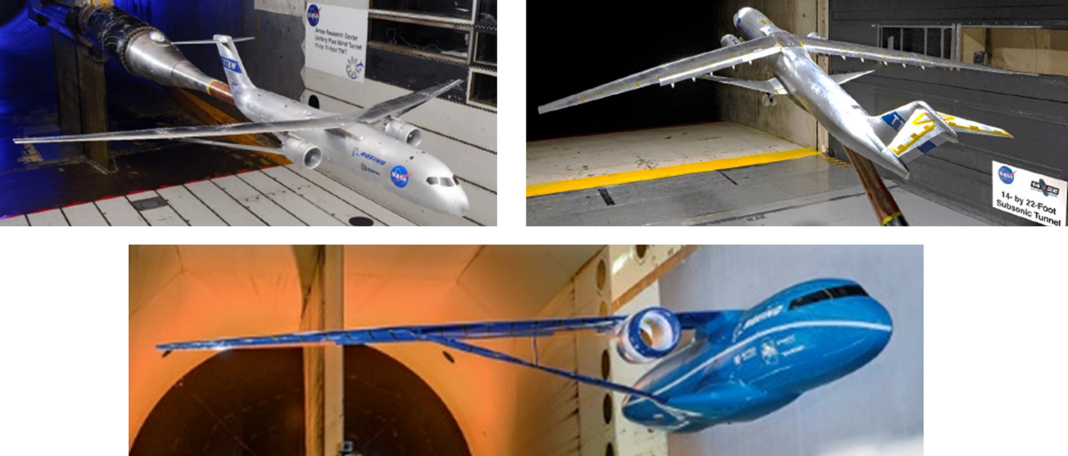
Figure 2. Transonic Truss-Braced Wing high/low-speed and aeroelastic wind tunnel models [Reference Harrison, Beyar, Dickey, Hoffman, Gatlin and Viken6].
The significant potential improvements to aircraft aerodynamic efficiency enabled by ultra-high-aspect-ratio wings is an important incentive for further development of a TTBW. In 1977 Werner Pfenninger postulated that the use of truss-bracing could enable ultra-high-wingspan designs with extensive laminar flow [Reference Pfenninger4]. In theory, these designs could achieve lift-to-drag ratios approaching 50. These theories were revisited in 1999 by a team of researchers at Virginia Tech, who performed MultiDisciplinary Design Optimisation of a transonic commercial transport with a strut-braced wing [Reference Gern, Gundlach, Ko, Naghshineh-Pour, Sulaeman, Tetrault, Grossman, Kapania, Mason and Schetz5]. Work performed at Virginia Tech (and other academic institutions around the world) has continued this research, producing articles and papers too numerous to list.
In 2008, building on early collaborative work with Virginia Tech, Boeing initiated the Subsonic Ultra Green Aircraft Research (SUGAR) program to explore advanced aircraft concepts with the potential for dramatic reduction in fuel burn, noise and emissions targeting a 2030–2035 entry into service. Over the past 12 years Boeing has worked with NASA under the Subsonic Fixed Wing (SFW) program to study a variety of different aircraft configurations and technologies. These studies have in recent years focused on understanding the promising potential of the TTBW concept as applied to a modern commercial transport. While the original SUGAR TTBW aircraft concept flew at Mach 0.7, these studies have evolved to focus on a Mach = 0.80 design. Computational studies and wind tunnel test programs under SUGAR have shown a potential fuel burn reduction of ∼9% for a 3500nm mission as compared to a cantilever-wing design of equivalent technology [Reference Harrison, Beyar, Dickey, Hoffman, Gatlin and Viken6]. The objective of the latest phases of the SUGAR program has therefore focused on further investigating and maturing the TTBW concept within the context of its potential applicability to modern commercial airliners. The primary attributes of the TTBW configuration that enable its potential to achieve these gains are:
-
a dramatic increase in wing aspect ratio, resulting in decreased lift-induced drag
-
structural efficiency from strut-bracing, resulting in decreased wing root bending moments
-
high-wing engine installation, enabling efficient integration of large-diameter high-efficiency propulsors
These design features have promising prospects for improved vehicle performance; however, they are not easily realised. The integration challenges of these same novel features result in design considerations not typically examined on a typical cantilevered-low-wing design. A (non-prioritised) subset of some of the primary considerations are:
-
non-linear structural design
-
non-linear aeroelastic behaviour
-
highly coupled transonic lifting surfaces
-
high-speed buffet
-
thin-wing actuation systems
-
high-lift system design and integration
-
thin-wing icing
-
achievable fuel volume
Over five phases, the SUGAR program has worked to systematically address these challenges through a series of design and testing activities. The design activities included structural design and analysis, detailed aerodynamic design for cruise Mach numbers ranging from M = 0.7 to 0.8, aeroelastic design and analysis, and high-lift system design. To date, the program has also completed six wind tunnel tests of the configuration to validate transonic cruise performance (in the NASA Ames 11-foot Transonic Wind Tunnel), high-lift performance including in-ground-effect and icing (in the NASA Langley 14- by 22-Foot Subsonic Tunnel), and aeroelastic behaviour (in the NASA Langley Transonic Dynamics Tunnel). Future investigations have also been proposed to increase understanding of additional aspects of the vehicle design and integration, including additional high-lift testing, acoustics quantification, more detailed icing investigations, and structural design and testing. NASA is also investigating the possibility of a large-scale flight demonstrator of the TTBW concept, which would continue the TTBW design validation efforts.
2.2 Flying V-configuration
The Flying V configuration is a radically new configuration for a long-haul passenger aircraft. The passengers, cargo and fuel are located in the wing (Fig. 3). It is estimated to have 20% higher payload-range efficiency than its tube-and-wing counterpart for the same top-level aircraft requirements [Reference Oosterom7]. This is caused by three factors. First, the absence of a distinct fuselage and tail reduce the wetted area by 5% leading to reduced friction drag. Second, the large winglets increase the effective span of the wing leading to a reduction in lift-induced drag. Finally, the lateral distribution of the payload and fuel reduces the bending moments and thereby the structural weight of the aircraft. These benefits stem directly from the shape of the aircraft and can be further complemented by innovations in the airframe or the propulsion system. Research into the viability of the Flying V is currently being performed primarily by researchers at Delft University of Technology. In the subsequent paragraphs, the Flying V design is further described and the associated challenges with this new configuration are discussed.

Figure 3. Planform view of the largest version of the Flying V configuration with 52 business class seats (55” pitch) and 309 economy class seats (32” pitch) [Reference Oosterom7].
As can be seen in Fig. 3, the cabin of the aircraft features a 3-4-3 configuration in both legs yielding four aisles. This reduces the boarding and deboarding time [Reference Isgro8]. A large cross aisle is present that connects the legs of the cabin with a large galley located in the middle. The door distribution is chosen such that the emergency evacuation can be ensured within 90 seconds for a high-density configuration of the cabin. The cargo compartment is located behind the cabin. To allow for the cargo nets to expand during a forward deceleration of 9g, space is reserved between the cargo containers and the aft cabin wall. The cargo containers that are used are of the LD4 type and are located in a tapering part of the wing. The fuel tank is located behind the cabin in the trailing edge of the wing as well as in the wing box of the outer wing. The economy seats are rotated by 9 degrees with respect to the cabin aisles to stay within certification constraints. The business class seats have seat belts with embedded airbags. By removing wing plugs (denoted in green and yellow in Fig. 3), smaller versions can be created such that a family of Flying V aircraft results.
The Flying V has a crescent wing planform with a 64-degree leading-edge sweep on the inner wing and a 40-degree sweep on the leading edge of the outer wing. The large inboard sweep angle allows for a cabin height of 2.1 meters without the formation of strong shock waves in the design condition [Reference Faggiano, Vos, Baan and van Dijk9]. The outer wing is designed as a traditional transport wing with supercritical wing sections. The low aspect ratio (around 4.5) combined with the high sweep angle result in a low lift-curve slope. Due to the large sweep angle of the inner wing, the stall of the Flying V is quite gradual with a maximum lift coefficient of around 1 [Reference Palermo and Vos10]. Depending on the Reynolds number, large vortex structures are formed beyond a critical angle of attack (see Fig. 4) that result in vortex lift. Since the outboard wing stalls first, there is a risk of a strong nose-up pitching moment. Therefore, a leading-edge slat or droop nose might be necessary to ensure acceptable low-speed stall characteristics.

Figure 4. Large vortex structures appear at high angles of attack over the inner wing of the Flying V [Reference Viet11].
The outer wing features various types of control surfaces. The most outboard control surfaces on the wing are multifunctional. They act as drag rudders and elevons. Together with the “normal” rudders on the large winglets, they provide sufficient yawing moment to control the aircraft in a one-engine-inoperative condition [Reference Cappuyns12]. The inner two control surfaces act as elevons controlling both pitch and roll. Secondary flight control surfaces in the form of spoilers are added on the inboard and outboard side of the engine. They ensure that 10% of the lift can be dumped upon landing. To ensure adequate flying and handling characteristics the aircraft is statically stable in pitch, roll and yaw. With the addition of a simple yaw damper and auto-throttle also dynamic stability is ensured in all modes (see Fig. 5). However, due to the absence of a tail, a strong coupling between the pitching and heaving movement is experienced which warrants the introduction of dedicated flight control laws for this configuration [Reference Garcia, Vos and de Visser13].
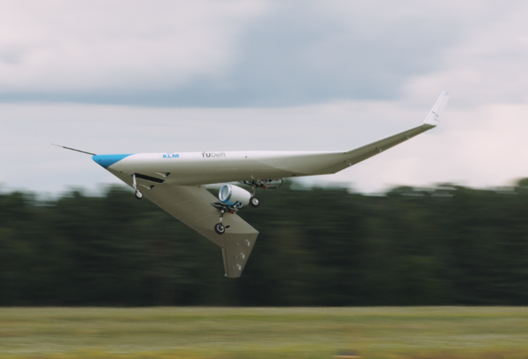
Figure 5. Flight control was experimentally verified using a 5%-scale flight-test demonstrator. Photo: Joep van Oppen for KLM and TU Delft.
The inner wing of the Flying V is pressurised. Therefore, an oval cross section is used with a piecewise circular perimeter. To ensure the structure does not deform upon pressurisation, a trapezoidal box structure is added inside this oval shape. The lower member of this trapezoid acts as the passenger floor. The outer wing primary structure is conventional, consisting of a box structure. The lateral distribution of fuel and payload reduces the stresses inside the structure compared to a conventional wing. This effect has been shown to outweigh the increase in stress due to the noncircular shape of the cabin cross section [Reference Claeys14,Reference Van der Schaft15]. However, further work is needed to detail the structure and assess it on a variety of loads such as crash loads or ditching loads. While the flight performance during climb, cruise and descent are not notably different from a tube-and-wing aircraft, the take-off and landing characteristics are quite different. Due to the low lift-curve slope of the wing, the aircraft has a maximal approach attitude of 14 degrees. Note that the aircraft does not feature any trailing-edge flaps to reduce its landing attitude. To allow the aircraft to have sufficient clearance at the tip during an 8-degree banked landing, long landing-gear legs are required and perhaps even an outrigger wheel (see Fig. 3) [Reference Bourget16]. However, operational constraints place the maximum height of the cargo door at 5.5 meters when the aircraft is completely empty. To stow the main landing gear efficiently in the wing, a double hinged mechanism is required [Reference Bourget16]. Furthermore, for a maximal approach speed of 140kts at the maximum landing weight, an overnose angle of 31 degrees is required to satisfy certification constraints on pilot visibility [Reference Van der Pluijm17]. This drives the shape of the cockpit, which is further complicated by the stowage of the nose wheel combined with the relatively low height of the fuselage.
The over-the-wing engine poses challenges in terms of structural integration, aerodynamics, noise, and maintainability. It is expected that the Flying V will utilise an ultra-high bypass-ratio engine, although it could also be suitable for an unducted fan. Due to the absence of wing reflection and the partial shielding of the inlet, the Flying V engine causes less community noise than an under-the-wing engine. Research is being conducted to investigate two integration options: positioning engine and nacelle on a separate pylon or blending the nacelle with the wing and allowing the wing boundary layer to be ingested by the inlet. The latter results in less wetted area, lower structural weight and easier maintenance while leading to lower total pressure recovery and higher fan distortion.
Research on the Flying V is still relatively recent, and it is still to be confirmed whether this configuration can meet all the certification requirements, while still achieving the improvement in payload-range efficiency.
2.3 Electrification of aviation
Aviation is undergoing a renaissance ushered in by a convergence of technologies that is enabling new aircraft designs, new missions, and new aviation business models. One of the most promising of these technologies is electric propulsion, which is fostering the greatest change to the design of aircraft since the advent of the jet engine. Electric propulsion comprises the reinvention of the aircraft powertrain, replacing fuel-burning internal combustion engines with electric motors, and replacing aviation fuels with energy stored in battery cells. Electric propulsion is now viewed as increasingly viable for aviation largely because of the recent progress in battery technology, power electronics, and motor technologies which have been advanced by industries ranging from consumer electronics to power tools. Underpinning these advances have been an array of fundamental breakthroughs stemming from fields as diverse as electrochemistry, material science, solid mechanics, microelectronics, and control theory.
Electric propulsion should not be thought of as a one-to-one replacement for fuel burning propulsion systems due to the relationship between the mission and requirements for an aircraft and the technology available for use in the aircraft’s design. In particular, the capabilities of any technology enable certain missions and requirements to be met practicably and affordably, and the limitations of the technology prevent other missions and requirements from being met practicably and affordably. For example, the unique capabilities of electric propulsion have created new categories of small UAVs, both fixed wing and VTOL. These new aircraft concepts are enabling new missions, allowing flight to be used in new and innovative ways.
All technologies have strengths and weaknesses, requiring decisions by aircraft designers to select the best technologies or combinations thereof to meet any particular mission and requirements. In this context, electric propulsion simply represents another choice of aircraft propulsion technology to add to existing options. For certain missions and requirements, electric propulsion will be feasible, and for other missions and requirements, conventional fuel burning propulsion will be feasible. Indeed, because electric propulsion is in its technological infancy, the space of possible missions and requirements that it can satisfy is smaller than that of conventional propulsion, most notably in terms of range performance. For a subset of missions and requirements, both electric and conventional fuel burning propulsion are technically feasible, and trade-off studies will determine which solution is preferred. Figure 6 illustrates these concepts of how electric and conventional propulsion address different missions and requirements.

Figure 6. Electric, hybrid electric and liquid fueled propulsion in the context of aircraft missions.
Considering these trade-offs, we can expect that aircraft designed for some missions and requirements may transition to electric propulsion, while other designs retain conventional fuel burning propulsion systems including piston engines and gas turbines. Other missions and requirements may motivate hybrid-electric propulsion solutions that leverage both fuel burning engines and electric propulsion components. The mission space depicted in Fig. 6 is not static, as technologies advance, we can expect the feasible mission bubbles for each category to grow.
That not all aviation missions and future aircraft designs will transition to electric propulsion does not diminish the importance of this emerging technology but rather frames its true opportunities. These opportunities lie in the space of requirements in Fig. 6 that electric propulsion can address but that conventional fuel burning propulsion cannot. This space includes requirements for emissions-free flight, low noise, and low maintenance costs. By enabling new aircraft designs that can address these requirements practically and economically, electric propulsion will enable aircraft to fulfill missions entirely new and transformational to aviation.
While the electrification of aviation represents an exciting future, we must anchor our perspective on the future on what has already been achieved. Figure 7 depicts a mosaic of electric and hybrid-electric aircraft; some piloted and some not, some production, representing hundreds of thousands of units sold, and some prototype. Some flight missions are already dominated by electric solutions — as electric component technologies move forward, the missions accomplished using electric propulsion will only expand.

Figure 7. Contemporary examples of battery electric, solar electric and hybrid electric aircraft.
2.3.1 Strengths and weaknesses of electric propulsion
A thorough understanding of the strengths and weaknesses of electric propulsion will guide our understanding of the kinds of new missions enabled by electrification and those ripe for conversion. Battery electric propulsion has several fundamental weaknesses:
-
Cell specific energy. Jet fuel contains about fifty times the energy as the same mass as lithium-ion cells. Cell specific energy is advancing at about 5%–7% per year but will remain the limiting technology for many missions for the foreseeable future [Reference Ziegler and Trancik18].
-
Recharging. Cells cannot be charged as quickly as liquid fuel can be transferred. The electrical grid may not be able to support rapid charging of large aircraft. A narrow body transport carries approximately 900 GJ in fuel and is refueled in about ten minutes, representing 1.5GW energy transfer rate. The energy transfer weakness includes the inability of electric aircraft to quickly refuel in-flight [19].
-
Cooling. In the Brayton cycle most of the waste heat is contained within the exhaust which leaves the system with substantial velocity. Although electric systems are highly efficient, even 1%–2% loss in high-power systems is a great deal of heat that must be disposed of. This heat is usually of low quality and may be created by buried components not amenable to air cooling.
-
Payload-range tradeoff. Battery electric aircraft do not have the ability to easily trade stored energy for payload, a mission flexibility enjoyed by conventional aircraft familiar through payload-range diagrams.
Electric propulsion also has many strengths that can enable new missions or yield advantages over conventional systems:
-
High Efficiency. On-board efficiency of an electric propulsion system is very high. Electric aircraft do not have the 30%–55% thermal efficiency penalty typical of combustion engines. This reduces the fuel vs. battery specific energy difference from 50x to between 15 and 28x.
-
Distributed Electric Propulsion (DEP). Components that make up electric propulsion systems are relatively scale-free compared to combustion systems, i.e. fundamental performance metrics such as efficiency, specific power, and specific energy remain relatively unchanged over several orders of magnitude change in scale [Reference Duffy, Sevier, Hupp, Perdomo and Wakayama20]. Designers of electric propulsion systems may consider many smaller components, fundamentally enabling Distributed Electric Propulsion (DEP). DEP can be a way of achieving redundancy and fail-safe systems without the same penalties as conventional systems. In one engine inoperative (OEI) sizing with N propulsors, the thrust of each propulsor must be sized to N/(N-1). A conventional twin-engine aircraft must be sized to 2x the nominal mean thrust while a DEP system with just N = 6 propulsors must be sized to only 1.2x the nominal mean thrust. When applied across the entire propulsion system, substantial weight and cost savings can be realised. Another DEP strategy is to capitalise on propulsion airframe interaction (PAI) such as the high lift propellers of NASA’s X-57 Maxwell [Reference Ginn21]. DEP can provide a means to use propulsors as control effectors, as in a quadcopter or perhaps a hybrid airship with distributed thrusters.
-
Scale-Free. The scale-free nature of electric propulsion also enables miniaturisation of components and by extension aircraft — small UAVs and micro air vehicles are enabled by electrification. For example, AeroVironment’s hummingbird [Reference Wiederhold22], Fig. 7i, and Harvard’s RoboBees [Reference Chen, Wang, Helbling, Jafferis, Zufferey, Ong, Ma, Gravish, Chirarattananon, Kovac and Wood23], Fig. 7h, are revolutionary biomimetic electric aircraft.
-
Simple Operation. Electric powertrains are simple to operate. The traditional cycle of engine startup, warmup, operation, shutdown, and cooldown is essentially eliminated. Electric powertrains can be started, stopped, and restarted at any time and without delay. Operational simplicity also makes electric powertrains suitable for operations in austere environments away from flight and ground crews; missions involving landing at remote unprepared sites perhaps to place sensors or to collect samples are simplified by electrification, e.g. the Mars helicopter Ingenuity (Fig. 7g). Similarly, air-launch, tube-launch, and other rapid response systems can be achieved with electric powertrains without some of the complication of using combustion-based systems in these roles. Motor drives can command nearly instantaneous torque changes, that fundamentally enables fixed-pitch RPM-controlled multicopters like the DJI Mini 2 (Fig. 7e). Motors can be controlled to be synchronised or phased, potentially enabling acoustic shaping and noise reductions.
-
Deep Throttling. Straightforward in-flight startup and shutdown of electric powertrains (or portions thereof) can enable the design of electric powertrains that suffer relatively little efficiency penalty when deeply throttled as compared to twin-engine combustion-based systems. Many missions require relatively short periods of high output combined with long periods of low output from the propulsion system. This problem is exacerbated when twin-engined aircraft are sized to the high-power requirement with one engine inoperative (OEI) but are required to cruise with all engines operating (AEO).
-
Lower Purchase Cost. Electric aircraft propulsion has the potential to dramatically lower costs. Electric motors and drives are less expensive to produce than either turbine or piston engines. Motors and drives can be manufactured via highly automated processes developed in the semiconductor and electronics manufacturing industries, and much of their overall complexity resides in software, which has zero replication cost. Electric motors enjoy a substantial reduction in number of parts and are subjected to much lower temperatures (350–430F or 180–220C) [24] than combustion engines (2,100–3600F or 1,200–2000C) [Reference Yin and Rao25]. Temperature plays an important role in performance, but not as combustion and thermodynamic efficiency as in turbine and piston engines. Like turbine engines, electric motors do not experience the reciprocating impulsive loads of piston engines; this leads to lighter structures with less vibratory and fatigue loading.
-
Lower Maintenance Cost. General aviation piston and small turbine engines typically have overhaul intervals between 1,500 and 5,000 hours and an overhaul cost about half the cost of a replacement engine. Large transport aircraft turbine engines have overhaul intervals as high as 25,000 hours and cost millions of dollars per engine. In contrast, the only scheduled powertrain maintenance for the Pipistrel Velis Electro (Fig. 7f) is a
 $\$ $
500 set of main bearings at 2000 hours. The Electro’s 21 kWh battery pack requires refurbishment between 700–1,000 hrs, but the cost of lithium-ion cells is continually being driven down by high-volume production in the electric automobile market, where pack costs are approaching
$\$ $
100/kWh. If an electric motor or drive needs replacement, these components may be treated as line replaceable units (LRUs) with simplified remove-and-replace procedures, reducing maintenance labor costs.
$\$ $
500 set of main bearings at 2000 hours. The Electro’s 21 kWh battery pack requires refurbishment between 700–1,000 hrs, but the cost of lithium-ion cells is continually being driven down by high-volume production in the electric automobile market, where pack costs are approaching
$\$ $
100/kWh. If an electric motor or drive needs replacement, these components may be treated as line replaceable units (LRUs) with simplified remove-and-replace procedures, reducing maintenance labor costs. -
Electric Energy Cost. Purchasing electricity from the grid enables electric aircraft to benefit from lower, and less volatile, economic, and environmental costs of energy. If the energy is produced in a renewable manner, the environmental cost of flight can be dramatically reduced. Even in the case where hydrocarbon fuels are used to generate electricity for the grid, shifting the fuel-to-usable-energy conversion burden to the ground allows improved efficiency through greater scale and the use of technologies that would be weight prohibitive for flight. Additionally, electric propulsion allows the terrestrial grid to adopt renewables at scale.
-
Reduced Noise. Electric propulsion systems can dramatically reduce noise by eliminating several prominent noise sources. By spreading thrust across multiple propulsors, DEP also opens the design space to include concepts with reduced tip speeds at constant disk loading, reducing tonal noise. Additionally, the instant-on operational characteristic of electric powertrains results in a dramatic reduction of community noise dose produced at the airfield as several minutes per flight of engine warmup and cooldown noise are eliminated.
-
Lower Emissions. Battery electric aircraft produce no gaseous, particulate, or lead emissions at the point of operation. If the electricity used to charge the batteries is generated renewably, then the carbon footprint and environmental impact of flight can be substantially mitigated. In addition, zero emissions at the point of operation can enable flight near buildings and HVAC systems. Similarly, electric aircraft are suitable for operation indoors and in environments that cannot be contaminated by the products of combustion, a requirement for some atmospheric monitoring missions. In addition, electric aircraft avoid the need for supportive infrastructure for the fuel and oil required by conventional aircraft.
-
No Power Lapse. Battery electric powertrains do not experience altitude lapse in the same way as combustion-based systems. Although the propeller, rotor, or fan’s performance is still affected by density lapse with altitude, the battery, drive, and motor’s ability to produce shaft power remain essentially unaffected. When flown through a wide range of operating conditions, electric powertrains pair well with variable pitch propulsors to best capitalise on the torque and power producing characteristics of the motor.


Somewhat ironically, although battery electric aircraft are limited in range and endurance due to the specific energy of cells, solar electric aircraft present an attractive means of achieving unlimited range or endurance. Solar recharging provides a continuous, during daylight hours, low power means of ‘refueling’ an electric aircraft in-flight.
2.3.2 Opportunities for electrification of aviation missions and aircraft configurations
As discussed and illustrated in Fig. 7, propulsion electrification will be suitable for some aviation missions but not others for reasons related to the inherent strengths and weaknesses of electric propulsion technology. Aircraft designed with electric propulsion to address these missions will have new configurations, departing from those of previous fuel burning aircraft designs. In some cases, the airframe configuration will change dramatically, with novel arrangements of lifting surfaces and multiple electric propulsors situated to achieve new capabilities for control, redundancy, flight performance, and acoustics. In other cases, the outer mold line (OML) of the airframe may appear nearly identical to that of an aircraft with a fuel-burning propulsion system designed to satisfy the same mission. However, we can expect that the inner workings of a well-designed electric aircraft configuration will be dramatically different. For this reason, we consider aircraft with electric propulsion to be fundamentally new configurations.
As a general guideline, a mission will be considered to electrify when battery specific energy exceeds a threshold above which it becomes technically feasible for the aircraft to meet its performance requirements. Above this threshold, the question will be primarily economic. Because battery specific energy is now reaching a level at which it is feasible to size an aircraft with a modest range and endurance performance suitable for some missions, we can expect that some missions may transition in the near term, and other longer range and endurance missions will continue to transition as battery technology improves over time.
2.3.2.1 Hybrid Electric Propulsion
For some missions, novel hybrid electric aircraft may ultimately become the dominant configuration if a fully electric propulsion system is impractical because of battery specific energy limitations. Hybrid electric propulsion incorporates one or several fuel burning engines alongside electric propulsion components such as motors, inverters, and (optionally) battery systems. Missions in this category will benefit from the ability to achieve new design degrees of freedom that make it possible to overcome historical limitations of conventional propulsion systems. In some cases, a hybrid system may make it possible to achieve higher fuel efficiency, higher reliability, improved safety, or lower maintenance. A particular challenge with hybrid electric configurations is to develop a configuration design, hybrid architecture, and hybridization strategy that results in a “best of both worlds” outcome, inheriting the advantages of both fuel-burning and electric propulsion systems instead of a “worst of both worlds” outcome in which the disadvantages of both types of propulsion system components dominate. Achieving this favourable outcome is particularly challenging because hybrid propulsion systems inherently involve more complexity than either fully electric or fully fuel burning systems.
An example is the Bell Electric Distributed Anti-Torque (EDAT) system, shown in Fig. 7b, which replaces the tail rotor in a conventional single main rotor helicopter [Reference Trevithick26]. The Bell EDAT is a technology development prototype aircraft; if it proves successful, the Single Main Rotor (SMR) electric tailrotor configuration may come to dominate SMR helicopter missions [Reference Head27]. Other missions may employ DEP to achieve favourable propulsion airframe integration (PAI) in which the DEP system enables increased aerodynamic efficiency or effectiveness of the airframe, or the airframe integration enables an increase in propulsive efficiency. One example would be a hybrid electric configuration similar to the fully electric NASA X-57’s Mod 4 configuration, in which a series of small ‘high-lift propellers’ blow the wing, increasing low-speed lift and allowing the wing area to be reduced to achieve higher cruise efficiency while maintaining field performance [19].
Certain missions may benefit from hybridisation even with conventional propulsion installations without DEP. Examples may include commercial transport aircraft with turboprop and turbofan installations that are augmented by ‘mild’ levels of hybridisation, in which electric propulsion components including motors, inverters, and small battery systems are used to transfer power between the high-pressure and low-pressure spools and/or to manage engine transient operability, allowing the engine to be optimised with reduced compressor stall margin, lower weight, or increased overall efficiency. Similarly, a hybrid system based on a strategy for peak power shaving may enable a relatively small battery system to augment power during takeoff and climb, allowing the gas turbine or piston engine to be downsized such that it operates at a more favourable, higher power and lower specific fuel consumption point on its throttle hook during cruise [Reference Finger, Braun and Bil28]. This latter strategy could also be extended by increasing the battery size to make it possible to employ a single gas turbine (instead of two) within a traditional twin propulsor configuration, with the battery providing additional power at takeoff and in the event of a failure of the gas turbine. Another possibility in this category is the use of a primary (single-use, non-rechargeable) battery for emergency takeoff power, allowing the gas turbines not to bear the burden of engine-out sizing, again facilitating cruise operations at a more efficient higher throttle point, and perhaps also providing weight savings.
2.3.2.2 All-Electric Propulsion
At present, radio controlled (RC) aircraft are overwhelmingly powered by an electric propulsion system consisting of a brushless electric motor, an electronic speed controller, and a battery pack. For the RC community, this one-to-one replacement of the propulsion system was valuable and useful, making RC flying more accessible and quieter.
One of the earliest piloted missions to electrify was that of a self-launched sailplane. Indeed, sailplane manufacturers were among the first to begin serious explorations of electric propulsion with piloted aircraft. By incorporating a motor on a deployable mast and powered by an inverter and small battery in the fuselage, a simple electric propulsion system provides the capability for a sailplane to launch from a field without need for a towplane. An electric self-launching system is also much quieter and more reliable than two-cycle piston engines that have been employed in the past, leading to a better flight experience more consistent with the reasons pilots enjoy sailplane flight. An example is the Lange Aviation Antares 20E sailplane, the first certificated, under EASA JAR 22, and serially produced electric aircraft.
Beyond sailplanes, other general aviation missions are beginning to adopt electric propulsion. A particularly exciting recent development is the certification in the CS-LSA category of the first electric-powered general aviation airplane, the Velis Electro, produced by the Slovenian company Pipistrel and shown in Fig. 7f [29,30]. The Velis Electro is a two-seat, high-wing, tricycle-gear aircraft with a single—certificated—electric motor powering a fixed-pitch propeller. The Velis Electro was developed from the basic airframe of the Pipistrel Velis, which is powered by a Rotax 912 piston engine. The Velis Electro is being sold to private pilots who desire a ‘green’ propulsion solution, a quiet in-flight experience, and as discussed above, an extraordinarily low cost per flight hour compared to a typical piston engine powered aircraft. The very low operating costs of the Velis Electro also make it appealing for primary flight training. The high cost of flight training has long been recognised as an impediment in recruiting new pilots to pursue aviation as a hobby or as a career and is at least partly to blame for the decades-long decline in the number of licensed pilots in the United States and other countries.
Other commercial general aviation missions including cargo transport and short-ranged passenger air service will also likely soon transition to electric propulsion. One example of this type of mission is the cargo feeder mission for overnight package delivery companies such as FedEx Express and UPS. In current practice, these missions are typically fulfilled by utility aircraft such as the Cessna 208 Caravan. The feeder aircraft carry packages from small regional airports to a major hub airport where they are transferred to jet transport aircraft such as 767s that then transport the packages to sorting centers. These feeder flights are typically short ranged. For example, a 2013 analysis of U.S. Bureau of Transportation Statistics data indicated that the FedEx Cessna 208 fleet flew less than 300 nautical miles 99.5% of the time and less than 200 nautical miles 91% of the time [Reference McDonald31]. These range requirements imply that battery specific energy will soon—if not already—be adequate for these cargo feeder missions. Additionally, the feeder aircraft typically operate a schedule of two flights per day, one in the early morning and one in the late afternoon; this schedule leaves adequate time for battery recharging during daytime and overnight hours.
Missions for short-range passenger air service are also becoming attractive applications for electric propulsion. Two missions that may see electric propulsion applications in the near term are chartered air taxi service, historically served with four-passenger fixed-wing single-engine aircraft, and commuter air service, historically served with nine-passenger fixed-wing twin-engine aircraft [Reference Stoll and Mikic32]. A particularly promising near-term application is very short-ranged commuter flights that overfly geographic or topographical features that preclude or complicate automobile trips. Examples include flights to coastal islands or between islands in an archipelago. As battery specific energy increases, shorter range regional aircraft missions may also become attractive applications.
2.3.2.3 Innovative New Missions
Leveraging new electric propulsion technology and the same basic airframe of an RC aircraft, an entirely new category of aircraft was made possible: hand-launched unmanned air vehicles (UAVs) used for surveillance and photography. This new category of aircraft, which began to emerge two decades ago, was particularly useful for military applications in which an individual soldier could carry and deploy a small airplane for tactical reconnaissance at the squad level to discover nearby threats hidden by the surrounding terrain. An example of this type of aircraft is the AeroVironment Raven, shown in Fig. 7d, which has been acquired by the U.S. Army and Marine Corps among others [33]. Electric propulsion is an absolute enabler of this mission because it offers whisper-quiet operation to prevent detection, simple start-up and reduced ground equipment compared to a small piston engine, easy battery swapping vs. complicated and messy refueling, and a nearly maintenance-free propulsion system.
A second example of a transformational mission enabled by electric propulsion is that of a high-altitude pseudo-satellite (HAPS). The key aspect of a HAPS mission is entirely foreign to aviation with fuel-burning propulsion: the ability to stay aloft nearly indefinitely, limited by component reliability rather than fuel capacity. As their name implies, HAPS typically “orbit” by loitering in a racetrack pattern over a particular geographic area for very long periods of time, providing satellite-like capabilities. HAPS missions include long-duration climate science, telecommunications relay applications, and military intelligence, surveillance, and reconnaissance (ISR). HAPS are powered by an electric propulsion system in which solar cells provide power for daytime flight and recharge batteries that are used for flight at nighttime. Typical configurations of HAPS aircraft have a very long and highly flexible wing made of composite materials, multiple motors and propellers distributed along the wing, and one or more fuselages and/or tail booms.
HAPS configurations typically employ span loading and are designed to maximise solar collection effectiveness. Examples include the Aurora Odysseus [34], the HAPSMobile/AeroVironment Sunglider [35], and the Airbus Zephyr [36]. Electric propulsion is the key enabler for HAPS missions because it makes it possible to harvest, store, and use solar energy to achieve flight with near-indefinite duration. Further contributing to this key mission attribute is the very high reliability of electric propulsion components, owing to their inherent mechanical simplicity with very few moving parts. Although not a HAPS, the Solar Impulse, shown in Fig. 7c, achieved the first around-the-world flight of a solar electric aircraft using similar technologies including solar cells, batteries, and a long-span lightweight wing, providing increasing confidence in the ability to develop effective HAPS aircraft [Reference Wei-Haas37].
Another example of a transformational mission enabled by electric propulsion is the small remotely piloted multicopter, an aircraft design that began to emerge in the early 2000s. Most typical examples of multicopters are quadcopters (four rotors) and hexacopters (six rotors). An example of a quadcopter is the DJI Mini 2, shown in Fig. 7e. Multicopters, colloquially known as ‘drones’ in the popular press, exemplify distributed electric propulsion (DEP) with multiple electric motors, each powering a rotor or propeller. Multicopters leverage the same fundamental electric propulsion technology as the RC electric aircraft mentioned above, namely lithium-ion battery packs, electronic speed controllers, and brushless DC motors. Unlike fixed-wing configurations, however, multicopters place additional requirements on the propulsion system beyond the production of thrust. In particular, they require the propulsion system to provide attitude control for the aircraft. Because multicopters are statically and dynamically unstable, the control system must be high bandwidth, leading to the need for rapid torque and/or speed response from the rotors. Achieving this bandwidth requirement with combustion engines would be especially challenging, necessitating rapid and mechanically complex rotor collective pitch control. However, electric motors can provide the needed torque and speed response, particularly for small scale aircraft, enabling multicopters to employ motor angular speed control with fixed-pitch propellers. The result is a small vertical takeoff and landing aircraft with extraordinary mechanical simplicity that can be constructed at very low cost from simple electronic components that are now available practically as commodities from the consumer electronics industry.
The applications and missions for multicopters has exploded in the past ten years, expanding from hobbyists and university research to a range of commercial applications with applications as diverse as aerial photography, package delivery, and application of agricultural chemicals. The commercial applications were enabled by certification of small remotely piloted aircraft operations through regulations such as FAA Part 107 [38]. Among the more interesting new markets and missions for multicopters is photography. Historically, aerial photography was cost-prohibitive, but with multicopters—fundamentally enabled by electric propulsion—the costs dropped orders of magnitude and drone photography is now widespread. Multicopters have democratised aviation in a way never achieved before, making it possible for anyone to buy or build and fly a small aircraft with very little training. Multicopters have also had dramatic impacts in research settings, with their simplicity and affordability making it possible to use the aircraft as platforms for carrying sensors and computing systems that enable fundamentally new lines of inquiry in a wide variety of fields.
Electric propulsion is also enabling a new aviation market known as urban air mobility (UAM). UAM is envisioned as a service in which vertical takeoff and landing (VTOL) air taxis transport passengers in a network of “vertiports” in a metropolitan area [Reference Holden and Goel39]. One might expect that helicopters could fulfill this role, and there are indeed historical examples of helicopter airlines operating in cities, most notably New York Airways’ service from Manhattan to LaGuardia airport in the 1950s–1970s [Reference Beresnevicius40]. However, these services have been severely limited because helicopters are noisy and have high operating costs, constraining operations and leading to a lack of profitability. UAM is now being reconsidered as an aviation market in large part because of the ability to implement distributed electric propulsion to design electric VTOL (eVTOL) aircraft, such as the Joby S4 shown in Fig. 7a. A wide variety of eVTOL aircraft configurations have been envisioned and designed, borrowing ideas such as DEP from multicopters and revisiting a wide variety of past VTOL concepts such as tiltrotors and tiltwings. In many ways, the explosion of interest in eVTOL aircraft is leading to a re-exploration of the ‘VTOL Wheel’ [Reference Hirschberg41] with electric propulsion. The VTOL Wheel, developed by Mike Hirschberg of the Vertical Flight Society (VFS), describes the wide variety of novel VTOL configurations, other than traditional rotorcraft, that were explored to achieve a balance between cruise performance and hover capability during the heyday of experimental aircraft in the 1940s–1970s. Particularly compelling eVTOL designs incorporate DEP with winged configurations to achieve the capability of hover for vertical takeoff and landing while also retaining the higher cruise efficiency of fixed wing configurations. The main potential advantages of eVTOL aircraft are reduced operating costs and reduced noise.
On 19 April 2021, the Ingenuity helicopter lifted off from the Martian surface in the first controlled, powered flight on another planet. Ingenuity, shown in Fig. 7g, was made possible by electric propulsion. Powered by a solar electric propulsion system including six lithium-ion battery cells and a total flight power of 350 W, Ingenuity could fly for a maximum duration of 90 seconds per Martian day [42]. Why was electric propulsion needed to enable flight on Mars? The most obvious reason is that fuel-burning engines “breathe” oxygen from the air to react with the fuel for combustion, and Mars’ atmosphere contains only 0.13% oxygen by volume compared to 21% on Earth and has surface atmospheric pressure approximately 1% that of Earth [Reference Sharp43], making flight-weight combustion engines impractical. A second reason is that Ingenuity is a research aircraft that is required to make multiple flights, slowly expanding its flight envelope, necessitating the ability to replenish energy between flights.
A solar electric propulsion system makes this process as simple as recharging the battery with the solar cells. The recharging capability also allows Ingenuity to operate completely independently from its mothership, the Perseverance rover, in contrast to a helicopter with a fuel-burning engine which would likely require transfer of liquid fuel to the aircraft from the lander between flights. As with any space science mission, the requirements for Ingenuity demanded extremely high reliability. Failures of any critical part at any phase of the mission could not be tolerated: Maintenance—other than software updates and remote commands sent from Earth—is impossible. Electric propulsion inherently offers much improved reliability compared to combustion engines because components have very few moving parts and, therefore, fewer opportunities for mechanical failures.
Micro air vehicles are an additional category of new missions that are enabled by electric propulsion. Examples include the Harvard RoboBee, shown in Fig. 7h, and the AeroVironment Hummingbird, shown in Fig. 7i. Low cost (
 $\$ $
20) COTS micro quadcopters (weighing a few grams and only a few centimeters in their greatest dimension) which are now widely available are an apt example of the scale-free nature of this technology.
$\$ $
20) COTS micro quadcopters (weighing a few grams and only a few centimeters in their greatest dimension) which are now widely available are an apt example of the scale-free nature of this technology.
Perhaps the most exciting space for electric aviation is in the missions no one has yet conceived. There may be a missed market between ladders and cranes for vertical lift on construction sites, maybe we need an electric drone to help with cleaning gutters, washing exterior windows, taking out the trash, or changing light bulbs.
3.0 Aircraft design methods
3.1 Empirical methods and data
Although future aircraft design process developments will someday combine model-based design (MBD) and artificial intelligence (AI) and fundamentally change how aircraft are designed, for now and the foreseeable future empirical design methods and data continue to start and sometimes complete the aircraft design process. The rationale is clearest for design databases since AI tools will almost certainly be database driven. The issue for empirical methods, however, is not whether they will continue to be viable and efficient which has already been established by Brandt and others [Reference Brandt44]. Rather, the issue is whether they will continue to (1) be applied in the design room and (2) taught in the classroom where future designers learn design fundamentals. The answer to the former will almost certainly be yes as discussed in section 3.2. However, the empirical lineage may not be obvious to users as the methods become increasingly integrated into higher-order codes as discussed in [Reference Carty45]. The most concerning issue is whether empirical methods continue to be taught as discussed in section 3.2.
From a historical perspective, empirical/data-based design methods trace to the 1930s when Professor K. D. Wood of Cornell University published the first of his Airplane Design series which was data driven and iterative. It started with requirements and an initial concept followed by data-based design cycles at increasing levels of fidelity intended to converge to a realistically sized concept capable of meeting requirements. The method used data from prior aircraft and essentially is what we know today as an empirical design method.
In its review of Wood’s text in 1935, the RAE Journal compared Wood’s approach to that used in British universities which we paraphrase as “consisting mainly of theoretical instruction with much of the information in the book not becoming known to most until arriving in industry.” Apparently, the reception to a text was sufficient for Prof. Wood to publish 10 editions through 1963 followed by his better-known Aerospace Vehicle Design Volume I – Aircraft Design [Reference Wood46]. The 1963 text devoted 189 pages to aircraft and rotorcraft design methods (mostly empirical) and another 238 pages to supporting design data.
Later followed Professor Roskam’s well-known, eight (8) volume Airplane Design series first published in 1985 [Reference Roskam47]. Roskam took empirical design methods to a higher-level of technical development. So, today aircraft design engineers and instructors have access to a wide range of excellent texts that combine empirical and physics-based methods across the aircraft design spectrum including books by AIAA Aircraft Design Technical Committee authors [Reference Raymer48–Reference Gundlach52].
One question for consideration here is where are empirical design methods and data headed or more importantly, how do they need to change to meet future needs as discussed in section 3.2? The first is an easy answer. Based on current trends, all methods and data will get absorbed by higher level master codes and at a detail level, may be known only to those involved in the care and feeding of the code. Working level engineers will give the codes problems to solve and let it pull up whatever it or engineering management considers the most applicable method. Working level engineers will still need to be familiar with the fundamentals of these methods so it’s important that they stay in the curriculum, or they really will get lost. The answer to the second question is that there are important things that need to be done today to make sure the most important methods and especially the data stay relevant for the next century of aeronautics.
3.1.1 Aircraft empirical methods and data: Industry design applications
This is a broad subject with many examples, most of which are proprietary. For established aircraft companies, they and their predecessors’ companies have decades of experience and data widely applicable across existing product lines. Methods are verified and often certified against the company database which makes the two essentially inseparable. In concept most company applications are similar and deal with a broad range of product design, analysis, test and support issues.
When companies are new and/or moving into new product areas, their database will be thin and the method applications risk will go up, but their basic technical approach typically doesn’t change. The process can start with a clean sheet or an existing product or some place in between. Regardless there is a need for quick initial answers with enough fidelity to make good decisions about whether to proceed. And this is where empirical methods are most widely applied. An example is the Roskam method shown in Fig. 8.

Figure 8. A typical conceptual aircraft design methodology [Reference Roskam47].
The Roskam method consists of two series of sequential conceptual design loops called Class I and Class II with the difference being fidelity. In both classes, empirical and physics-based methods are used with most Class I being empirical. For example, initial mass property estimates are almost always empirical with the difference between classes being fidelity. For example, a Class I empty weight estimate might be based on an empirical gross mass data as shown on the left side of Fig. 8 or built up by component such as the wing mass based exposed wing area and type shown on the right side [Reference Roskam47]. Class II might break the wing down into the wing box and control surfaces and flaps. Class I empennage sizing is also almost always initially based on historical tail volume coefficients which go through critical sizing checks for nose gear liftoff in Class II. Early aerodynamics and volume required estimates are also empirical. Class II aero estimates are typically physics based (CFD) but typically address major components with details such as intersections and fairings estimated from data. Structural layouts may not be called empirical, but they are based on prior vehicle layout experiences as are propulsion installation loss estimates. An example of a physics-based Class I is a static balance calculation based on estimated component mass and location, some of which such as alighting gear location are based on experience. Regardless of the specific methods, the objective is almost always the same – assess the concept and see if it works. Usually, the first one does not so all early cycles need to be done quickly [Reference Chaput and Mark53]. In fact, the motto of my design room at General Dynamics Fort Worth was “you have to kiss a lot of toads before you find a prince.” [Chaput]
Even after a concept is evaluated and selected for development, empirical estimates continue in use. For example, at a preliminary Design Review where the objective is to freeze the outer mould line and major structural locations, component masse beyond the “big bones” are estimates as are target weights [Reference Chaput54]. Even at a critical design review (CDR) where the objective is to get permission to start releasing drawings to the factory, most smaller airframe component masses continue to be empirically based. So, the prospects for continued application of empirical methods in industry are almost guaranteed and the only place where they will continue to be called into question are at places that do not do real designs, i.e. at universities.
3.1.2 Aircraft empirical methods and data: Design education applications
Although today’s texts apply a variety of methods, the fundamental concepts are similar in that the initial objective is to educate students on how to define a realistically sized starting concept that should work. A second common attribute is the use of data to ensure that intermediate and final results are realistic. What is typically not emphasised is industry-standard, multi-concept exploration and iteration towards the objective of identifying a “best” concept vs. one that simply works. The reason is design course schedule constraint, even empirical concept exploration methods are time-consuming. One solution is parametric model-based design (PMBD) education where traditional empirical methods are integrated with physics-based parametric geometry models [Reference Chaput and Mark53]. Once developed by a student, a PMBD model can be used to calculate performance and also morphed into a variety of alternative concepts for comparison and ‘optimisation’ to best meet design requirements. The term ‘optimised’ is widely used in the classroom but often misunderstood by students. Optimisation is process of multi-discipline compromise to achieve a compliant but better-balanced design.
Regardless of design methods used in the classroom, a common issue for all instructors is student understanding of how the methods are applied which, by definition, involves comparisons to design data. While the future could bring design education processes that enable theory to be applied without comparisons to real aircraft, one must question the educational rationale. On the job, students will be dealing with real products that have to work across multiple users and disciplines, so taking real products out of the design education process would be a return to the pre-1935 methods discussed in the introduction. The key issue, therefore, is the availability of data, its form and how it is applied in design education.
The availability issue has been with us for a long time and is getting worse. Almost everything about a commercial aircraft design below the empty weight (EW) level is considered proprietary, particularly mass properties. The situation for military aircraft is similar except the issues are not only proprietary but national security related. Yet some of the most recent data in education design databases is for military aircraft while commercial aircraft of similar vintage are missing. In fact, about the only detailed mass property data on civilian aircraft is for military variants of the same aircraft, which is indeed strange.
The form of the data is another issue. Much of our aeronautical data goes back to the period from 1930 through 1960 where data was plotted graphically as a part of the analysis process. The plot variables were traditional and typically two-dimensional. Much of the aerodynamic and propeller data is still relevant and widely used. The basic form, however, is graphical which limits application of modern, multi-dimensional analysis methods. What’s needed is digital data and it’s not widely available.
Another issue is availability of data on modern aircraft or modern forms. Except for companies trying to break into a new product line, this may not be an issue for industrial designers where the most important data is in their own product archives because they reflect internal processes, procedures and capabilities. But for educational purposes our data base is not only old and cumbersome to analyse but so old as to be a turn-off for students, including for research.
If the data availability and form issues can be mitigated as discussed in Section 4, the next most important issue is how we teach student to think about and use design data. It is a fact of life that engineering education emphasises equations, especially derivations. And one design education issue is equations derived from data. An example is a widely known data plot used for initial aircraft sizing in the form of a log plot of flight design gross weight (FDGW) vs. EW as shown on the left side of Fig. 9.

Figure 9. Comparison of curve fit vs. physics approaches to design data.
FDGW is approximately the sum of EW plus flight design useful load (UL) where UL is driven by requirements that can vary widely, even within aircraft types. Nonetheless, students learn to make initial estimates of EW from FDGW using curve fit equations with emphasis on the equation. What is important, however, is not the equation but the physics. For example, plotting the same data in a wing loading form as shown on the right side of the figure and discussing the relationship with lift coefficient (CL), teaches the concept of physics-based limits within which requirements and designer choices define the design outcome.
Once students learn to start thinking about the physics of design data, they are better prepared to intellectually deal with our most widely misused data-based relationships in aerospace, which are mass property parametrics where curve fit equations are all students see. The equations mask the underlying data scatter and constraints and leads to over-reliance on equations vs. data. As a result, students routinely apply the relationships where they do not apply and are confused about why things did not work out in the end.
3.2 Future trends
Since the earliest days of aircraft design, historical data and derived empirical relationships have been the basis for sizing and performance correlation. The methods are still widely used and applicable and will probably stay that way for the foreseeable future. However, as modern design tools and methods continue development, the underlying data and relationships, are likely to become imbedded in higher level methods and lose their identity and understanding including limitations on application. It is important, therefore, that the basic methods be taught, understood and properly applied by future designers.
The antiquity of current publicly available design data is a serious issue for design education, especially for commercial aircraft. Contemporary data plots are often limited to first- and second-generation jet aircraft that have been out of service for longer than most students have been alive. The issue is the proprietary concerns of manufacturer legal departments that apparently do not recognise the silliness of maintaining close hold of antiquated data. It helps fuel the concept among students that aeronautics is old fashioned when in fact behind the proprietary walls, aeronautics is as cutting edge as any other discipline.
Although it is unlikely that manufacturers will yield on proprietary concerns, they should at least be willing to release data to trusted agents able to sanitise data to mitigate proprietary concerns that could give the design database a significant refresh. A useful but dated model of the trusted-agent concept was when the U.S. Air Force, which tasked the RAND corporation to sanitise aircraft manufacturer cost data and generate cost estimating relationships still used today, albeit based on ancient data that also needs a refresh [Reference Boren55].
Another option is for sponsored research where well-documented historical aircraft such as early jet transports are updated with modern materials, subsystems and propulsion. Included would be validating the results against a sanitised modern counterpart aircraft. These would not only be good graduate student team research projects but help teach modern methods of design.
A final issue is the 2D data plot format of design data which is still highly relevant. Those plots may have been useful for yesterday’s engineering, but today’s data needs are digital. This means funding is needed to republish prior reports with digitised data files.
3.3 Multidisciplinary Design Optimisation (MDO)
Aircraft design requires a team of engineers and leaders transform a set of requirements into mathematical models, then into blueprint drawings and specifications, and finally, into physical hardware. Aircraft design requires expertise in diverse engineering specialties including applied mathematics (computer programming and numerical analysis), aerodynamics (for external and internal flows), acoustics, thermodynamics, materials science, chemical engineering, electrical engineering (power generation, RF applications and control theory), structural mechanics (statics and dynamics), machine and mechanism design as well as manufacturing engineering and operations research. Aircraft design also requires engineers to interact with a broad set of non-engineering disciplines, including law, finance, marketing, accounting, meteorology, supply chain, industrial design and even diverse professions such as fashion merchandising [Reference Takahashi56].
Aircraft sizing has always been a numerical, multi-disciplinary exercise. Traditionally, this work was distributed amongst many engineers working in relatively siloed disciplines; refer to Fig. 10. Classical aircraft sizing depends upon the use of highly simplified models that capture the multi-disciplinary interactions among weights, aerodynamics, propulsion and performance [Reference Hays58]; this is expressed in Loftin’s thrust-loading/wing-loading constraint chart [Reference Loftin59] made famous by Roskam [Reference Roskam47] amongst others (Fig. 11).

Figure 10. Classical aircraft design problem [Reference Carty45].

Figure 11. Classical thrust loading/wing loading constraint chart.
Multi-disciplinary optimization (MDO) grew from operations research. In many ways, the former U.S. Defence Secretary, Robert McNamara, is the father of MDO. He and his other ‘whiz kids’ got their start during WWII tasked with providing a scientific method to provide a quantitative basis for decisions regarding the operations under their control [Reference Morris, Williams, Ahlberg, Chappell, McNamara and Glass60,61]. These defence studies performed critical analyses to aid the war effort. For example, to optimise the size of transport ship convoys as to best minimise losses. Operations research provided counterintuitive insight showing that vulnerability was most correlated to the number of escort vessels present, rather than the size of the convoy [Reference Gannon62].
By the end of the 1950s, operations research principles began to influence many attributes of design. Beginning with his 1960 landmark paper [Reference Schmit63], Professor Lucien Schmit lead the transformation of engineering design from an analytical (calculus and asymptotic expansion-based methods) pursuit to one involving direct numerical solutions. Schmit began his career at Grumman and later transitioned to academia. He and his student Garret Vanderplaats played a transformative role in introducing gradient-based optimisation methods to transform finite-element structural analysis methods into structural design synthesis codes [Reference Vanderplaats64].
After achieving considerable success with structural design and NASTRAN during the U.S. space programme, operations research inspired multi-disciplinary optimisation techniques grew in scope. During the 1980s and 1990s at NASA/Langley Research Center, Jaroslaw Sobieski championed decomposition methods specifically designed for MDO applications. Sobieski emerged from the NASA structures community [Reference Tolson and Sobieszczanski-Sobieski65] during the formative years of MDO, he collaborated with many academic groups, particularly those at Virginia Tech [Reference Grossman, Haftka, Kao, Polen, Rais-Rohani and Sobieszczanski-Sobieski66]. At the United States Air Force, Dr. V.B. Venkayya played a similar role; coming from a flutter and structural-dynamics perspective; he was instrumental in developing the ASTROS aero-structural design system [Reference Herendeen, Hoesly, Johnson and Venkayya67].
Modern MDO methods are composed of a variety of approaches. Many consider Isaac Newton as the grandfather of optimisation, having devised an efficient root-finding algorithm in 1669. This ‘gradient method’, which can be extended to consider millions of design variables [Reference Martins68], includes various methods including those which directly and indirectly (i.e. penalty functions) impose constraints as well as algorithms such as methods of feasible directions, conjugate gradients as well as sequential linear programming and sequential quadratic programming methods [Reference Vanderplaats69].
Alternatively, non-gradient-based methods, including genetic algorithms, simulated annealing and ant colony algorithms, have also become popular to apply to complex problems that do not present objective functions with clear local maxima [Reference Vanderplaats69].
Finally, modern computers with high-pixel density displays enabled the growth of design space visualisation methods. These tools directly involve the human to determine the preferred solution; they have become popular with complex multi-objective design problems with poorly understood constraints; see Fig. 12.

Figure 12. System level sensitivities to design variables for a notional HSCT [Reference Mavris, Bandte and DeLaurentis70].
Commercial aircraft design software embodying MDO principles includes monolithic packages (which include all germane analysis and optimisation methods) and extensible frameworks. Daniel Raymer’s RDS [Reference Raymer71], NASA’s FLOPS [Reference McCullers72] and Professor Jan Roskam’s DAR Corporation AAA [Reference Roskam and Anemaat73] are examples of the classic all-in-one MDO tools. At the other end of the spectrum are trade study environments such as Phoenix Integration’s ModelCenter [Reference Malone and Woyak74] or NASA’s OpenMDAO [Reference Gray, Moore and Naylor75].
The modern industrial MDO era is largely tied to existence of reliable commercial software. For an aircraft systems design perspective, the late 1990s reflected a paradigm shift from monolithic codes (in-house equivalents to Raymer’s RDS or NASA’s FLOPS) to those employing a flexible trade study environment (such as JMP and/or ModelCenter). Whereas many monolithic codes goals were to develop a classical wing-loading/thrust-loading plot, albeit using a higher-fidelity basis, flexible trade study tools enable engineers to make ‘run-time’ choices and explore high-dimensionality design spaces in a fundamentally different manner.
Since 2000, major airframe primes have showcased their in-house MDO capability as applied to different system design challenges. These published studies move far beyond classic wing-loading/thrust-loading constraint plots. In 2004, Carty & Davies at Lockheed Martin Skunkworks showcased the use of ModelCenter as a fusion environment linking numerical tools directly to CAD interface; see Fig. 13. Boeing showcased similar capability in 2006; Vandenbrande [Reference Vandenbrande, Grandine and Hogan57] emphasised the critical need for design-space-exploration as an integral part of the MDO process; see Fig. 14. High-speed vehicles have been an area of particular interest, as they are much more coupled designs than subsonic transports. In 2005, Raytheon Aircraft showcased MDO tools applied to low-boom supersonic business jet design [Reference Aronstein and Schueler77]. One year later, Raytheon Missile Systems demonstrated how they included aero-thermal effects in their ModelCenter-enabled MDO sizing tool used to screen high-speed weapons concepts [Reference Cunnington, Takahashi and Bays78].

Figure 13. Aircraft design employing CAD integrated with analysis using ModelCenter [Reference Carty and Davies76].

Figure 14. Design space exploration using statistical methods [Reference Carty45].
As basic MDO frameworks matured, we see government laboratory lead system-design MDO studies expanding existing models to include new disciplinary elements. For example, the EU Clean Sky joint-technical programme brought together government laboratory researchers, EU based industrial partners as well as academic researchers. In such an endeavor, MDO frameworks provide an essential collaborative function between the many developers and users. Clean Sky related publications include government/academic teams [Reference Hecken79] as well as small business [Reference Schneegans80]. In the United States, NASA sponsored several MDO-centric efforts including N + 2 supersonic airliner [Reference Magee81] and environmentally responsible aircraft studies [Reference Schutte and Mavris82]. Also in the United States, military-focused MDO programs have included the Air Force Research Laboratories led Efficient Supersonic Air Vehicle (ESAV) effort, which produced MDO papers led by major airframers [Reference Davies, Stelmack, Zink, De La Garza and Flick83], government staff [Reference Alanyak and Allison84] as well as university researchers [Reference Allison, Morris, Schetz, Kapania, Watson and Deaton85].
3.4 Collaborative design
The complexity of aircraft design has grown significantly over the past 120 years. While the Wright brothers’ aim was demonstrating controlled flight, the requirements for current commercial or military aircraft have risen due to a continued interplay between user demand and technology capability. Good flight performance is no longer the only objective, the aircraft must meet increasing noise and emission requirements, economic constraints, passenger appeal, maintainability, repairability, safety, etc. Therefore, solving current and future aircraft design problems require a collaborative effort from engineers, scientists, economist, aircraft operators, supply chain partners, government agencies, regulatory agencies, etc. These disciplines must be considered equally throughout the design process, as outlined in section 3.3, and all design decisions must be underpinned by top-level requirements (TLR). In multi-disciplinary design, disciplines are still standalone but interact with each other through data exchange. Some design decisions are still made within disciplines if this is considered reasonable or practical at the given stage of the design process, without necessarily linking them to TLR. In the future disciplines will become more integrated in a transdisciplinary environment where disciplinary boundaries become blurred, and all design decisions are driven by TLR.
System engineering has characteristics of art and science because good system engineering requires the creativity and knowledge of systems engineers, but it also requires systems management and the application of a systematic disciplined approach. The traditional design methodology is the sequential approach where specialists working ‘in series’ with feedback loops to previous steps. Lack of communication among the specialists cause incorrect assumptions to be adopted and the main system parameters are not monitored in real-time. This method reduces the opportunity to find interdisciplinary solutions and to create system awareness in the specialists.
Concurrent or Collaborative Engineering is as an alternative to the classical approach and provides better performance by taking full advantage of modern information technology (IT) (Fig. 15). Experts from various disciplines are co-located, either physically or virtually, and can communicate in real-time. As a result, many disciplines are involved in the design process and the concurrent approach has been proven to be particularly effective for complex systems design [Reference Fortescue, Swinerd and Stark86].

Figure 15. Collaborative Design process.
A definition of concurrent engineering adopted by the European Space Agency (ESA) is [Reference Bandecchi, Melton and Ongaro87]:
Concurrent engineering is a systematic approach to integrated product development that emphasizes the response to customer expectations. It embodies team values of cooperation, trust and sharing in such a manner that decision making is by consensus, involving all perspectives in parallel, from the beginning of the product life-cycle.
Concurrent or Collaborative Design requires an IT environment and information system, a so-called collaborate design facility (cdf), allowing domain experts to communicate, share data, conduct design analysis, display results, etc. A CDF can be a centralised facility but will likely be connected to other sites in the organisation. Key elements of a CDF, include process, multidisciplinary team, integrated data model, appropriate facility and software infrastructure, will be discussed.
3.4.1 Background and history
Some attempts at concurrent engineering in aerospace and defense began in 1980s. In 1988, the Integrated Process Laboratory at the Concurrent Engineering Research Center (CERC) was established at West Virginia University by the Defense Advanced Research Projects Agency (DARPA) to promote CE to the U.S. industry. A survey showed that the major impetus in moving to a CE environment was seen to be the potential of reduction in overall costs and design time, as a pathway to be competitive and to improve product quality. It also showed that most pressing need was to foster a teamwork environment and that a greater leverage exists in teamwork and process improvement [Reference Lawson and Karandikar89].
The first CDF with full features, called the Project Design Center (PDC), was opened by the Jet Propulsion Laboratory (JPL) in 1994 [Reference Smith90]. The PDC provides a facility, with multiple rooms, for design teams to use to conduct concurrent engineering sessions. The Aerospace Corporation had developed the process and the tools for CE almost at the same time and they had been successfully applied to several programs. Based on this experience, the JPL contracted the Aerospace Corporation to develop CEM processes and tools for the PDC. The Concept Design Center (CDC) was established by the Aerospace Corporation in 1997 to enhance support to its customers by providing a process for bringing together the conceptual design capabilities and experts [Reference Aguilar, Dawdy and Law88].
In the European space industry, concurrent engineering was applied to spacecraft design from the beginning of 1990. The first establishment was the Satellite Design Office (SDO) at DASA/Astrium, with the cooperation of the System Engineering (SE) group at the Technical University of Munich. An experimental Concurrent Design Facility (CDF) was established at the ESA Research and Technology Centre (ESTEC) at the end of 1998 and used to performance the assessment of several missions. It is primarily used to assess the technical, programmatic, and financial feasibility of future space missions and new spacecraft concepts. Additionally, the ESA CDF is also used for many other multi-disciplinary applications, such as payload instrument preliminary design, System of System (SoS) architectures, space exploration scenarios, etc. [Reference Koning93]. The facility was upgraded in 2008 and has since delivered a design time reduction by a factor of 4 and a cost reduction by a factor of 2 [Reference Koning93]. Some Collaborative Design facilities in operation are shown in Fig. 16.

Figure 16. Concurrent design facilities.
3.4.2 Key Elements in collaborative design
As shown in Fig. 17, a typical CDF includes the following key elements: a process, a multidisciplinary team, integrated design models, an IT facility, and a software infrastructure [Reference Bandecchi, Melton, Gardini and Ongaro91]. These elements are described in more detail, based on the CDF implementations at ESA/ESTEC. However, the concept of a CDF can be applied to solving a complex design problem as the only difference is in the design models which have to be specific.

Figure 17. Elements of a concurrent design facility [Reference Braukhane92].
3.4.2.1 Process
Complex systems have many interdependencies between components. This implies that the definition and evolution of each component has an impact on other components and that any design change will propagate through the system. Early assessment of the system-level impact of changes is essential to ensure that the design process converges on an optimised solution.
The process defined way the team will work together. It typically starts with a preparation phase in which the team and the customer meet to refine and formalise the mission requirements, define the constraints, identify design drivers and estimate the resources needed to achieve the objectives. Then a kick-off takes place and the design process starts. It is conducted in a number of sessions in which all domain experts participate. This is an iterative process that addresses all aspects of the system design in a quick and concurrent fashion. One key factor is the ability to conduct a process that is not dependent on the path followed. At any stage it must be possible to take advantage of alternative paths or use ‘professional estimates’ to ensure that the process is not blocked by lack of data or lack of decisions.
3.4.2.2 Multidisciplinary team
Human resources are the most important and crucial element. A fundamental part of the Collaborative Design approach is to create a multi-disciplinary team representing all relevant domains that performs the design work in real-time. The collective approach, the collaborative environment, the intense and focused effort and clear objectives are all essential elements that contribute to personal motivation.
For each discipline representation is created within the facility and assigned to an expert in that technical domain. Each position is equipped with the necessary tools for design modeling, analysis and data exchange. The choice of disciplines involved depends on the level of detail required and on the specialisation of the available expertise. The number of disciplines may be limited initially, especially in the first experimental study, to avoid extended debate and to allow a fast turn-around of design iterations.
3.4.2.3 Integrated design models
The design process is model driven, using information derived from the collection and integration of the tools used by each specialist for their domain, that allows generic models of various mission/technological scenarios to be characterised for the study being performed (Fig. 18). A parametric approach supports fast modification and analysis of new scenarios, which is essential for the real-time process. It acts as a mean to establish and fix the ground rules of the design and to formalise the responsibility boundaries of each domain. Once a specific model is established it is used to refine the design and to introduce further levels of detail.
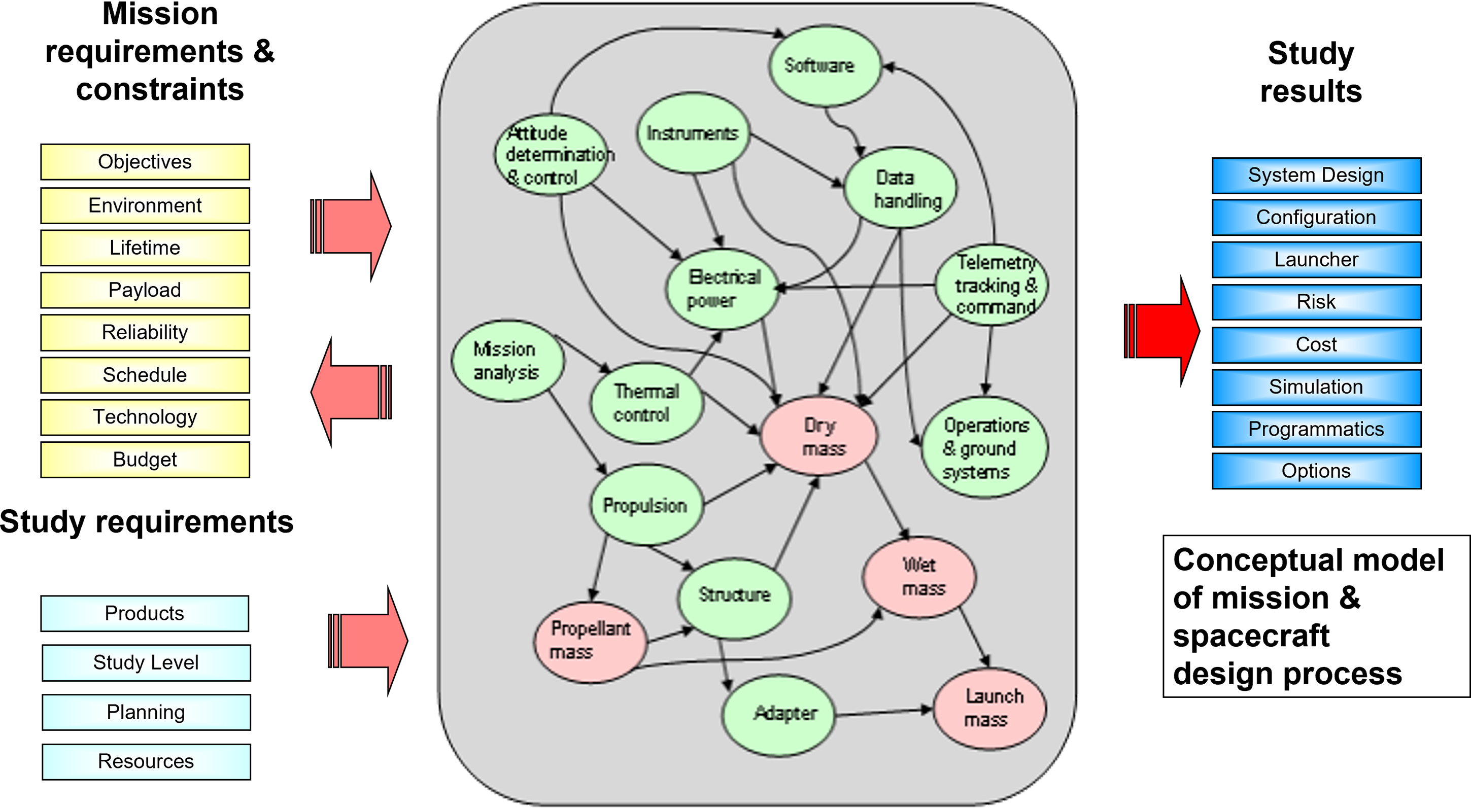
Figure 18. Conceptual model of the mission and spacecraft design process [Reference Koning93].
Each model consists of an input, output, calculation, and results area. The input and output areas are used to exchange parameters with the rest of the system (i.e. other internal and external tools and models). The calculation area contains equations and specification data for different technologies to perform the actual modeling process. The results area contains a summary of the numeric results of the specific design to be used for presentation during the design process and as part of the report at the end of the study.
3.4.2.4 IT facility
The team of domain experts meet in the Concurrent Design Facility (CDF) to conduct design sessions. The accommodation generally comprises a design room, a meeting room and project-support office space (Fig. 19). The equipment location and the layout of the CDF are designed to facilitate the design process, the interaction, the collaboration, and the involvement of the domain experts. The facility is equipped with computer workstations each dedicated to a technical discipline. A central multimedia wall, supporting two or three large projector screens, can show the display of each workstation, so that the specialists can present and compare design options or proposals and highlight any implications imposed on, or by, other domains.

Figure 19. The ESA/ESTEC concurrent design facility layout [Reference Koning93].
3.4.2.5 Software infrastructure
An infrastructure to implement the Collaborative or Concurrent Design Facility hardware outlined above requires software tools for the generation domain models with a means to exchange data between models in real time, a means to incorporate domain-specific tools for modeling and/or complex calculations, a documentation-support system, and storage capability (Fig. 20). The infrastructure must allow domain experts to work remotely from other sites, and exchange information easily between the normal office working environment and the CDF environment.

Figure 20. Architecture of the software model [Reference Koning93].
Domain-specific tools by each expert have to be integrated into the infrastructure of the facility. This aspect of the infrastructure can be improvement over time and will enhance the concurrency of the design process. In some specific cases, e.g. the interface between domain specific tools, it is more convenient not to use the centralised data exchange, but rather to create a direct interface between applications. An example of such an interface is the transfer of geometrical 3D data of the design configuration to the simulation system, which uses geometric models for visualisation.
3.4.3 Future trends
With the rapid developing of new technologies, aerospace industry is facing the huge challenge in how to design complex aircraft or spacecraft systems at low cost and short lead times. There are many design alternatives which need to be evaluated and screened. CDF based on concurrent engineering methodology is an effective and efficient approach to solve this problem. Many case studies have shown that a CDF can dramatically reduce the time and cost to complete the design missions compared with traditional design process. Many industries and academic research institutes in the field of aerospace are implementing or are developing their own CDF. It is obvious that more aerospace vehicle designs, and flight mission assessments will be conducted in CDF and aerospace engineering education in the CDF environment will also be a trend in many universities.
Aerospace vehicle design involves different disciplinary and integrate them into a complex engineering problem. In CDF environment, specialists in each domain contribute their knowledge and experience to solve this problem. But human design decisions are always affected by some personal subjective factors, and it is difficult to obtain an optimal result. Application of MDO methodologies in CDF will be powerful to accelerate convergence to optimal results by automatic data exchanging and searching progress rather than hand-on trade-off design results.
Future aircraft and aerospace vehicle design will also need to consider the cost of operation, turn-around and maintain, etc. Thus, CDF should extend the applicability across the project lifecycle. Large scale aerospace mission projects generally are undertaken by international cooperation. Collaborative distributed design ability will be requirement for the future CDF [Reference Fan, Zhu, Bok and Kumar94–Reference Boöhnke, Nagel and Gollnick96].
Acknowledgement
The Flying V project has been sponsored by KLM Royal Dutch Airlines.


