Here I present a “how-to” guide to produce accurate copies of lithic artifacts for use in experimental studies that require large numbers of nearly identical copies. This method evolved from research questions about knappers’ failure rates at the fluting stage of Folsom projectile point production. It became apparent that it would be an expensive and long-term process to create hundreds of lithic replicas. The new method presented here is not a replacement for other traditional approaches to answering critical questions in experimental lithic studies such as raw material selection, decision-making, and skill assessment, among others. It is, however, an alternative strategy to assess numerical and mechanical questions about flake morphology and breakage patterns affiliated with successful and unsuccessful strikes and to possibly provide alternative approaches to gauging skill level at particular stages in flintknapping. The subjectivity of the researcher and the knapper is kept to a minimum through enhanced control when certain observable criteria are desired. The method presented here is one approach of many to answer specific questions that concern lithic production experiments (Marsh and Ferguson Reference Marsh, Ferguson and Ferguson2010).
BACKGROUND
Flintknapping is an irrevocable process of reduction. While similarities in form, debitage, and process can be re-created experimentally, the archaeological form in the chaîne opératoire is approximated (Andrefsky Reference Andrefsky2005). By sharing a process for creating nearly identical lithic tool facsimiles, this article provides a new method for engaging experimental studies in lithic production. This method attempts to eliminate some of the inconsistencies in experimental knapping when specific stages need to be recorded or the production of a large sample population is not feasible with traditional approaches. Advantages of this new method over traditional approaches to flintknapping experiments include allowing the flaking of highly precise facsimiles of actual artifacts; the recording and replication of critical stages in the reduction process, such as creating a Folsom preform ready for fluting (see Figure 1); and the production of a large number of these precise replicas at a relatively low cost. The methods described here obtain optimum reproduction of surface details and similarity in size by using a Cone 10 porcelain slip. The use of porcelain as a proxy substrate for knapping has been presented by previous researchers (Khreisheh, Davies, and Bradley Reference Khreisheh, Davies and Bradley2013; Tsirk Reference Tsirk2014) and will be discussed in terms of its mechanical properties in relation to knappable stone used in prehistory. Porcelain is used for experimental lithic studies because of its fracture toughness values and because it is comparable to some materials used in prehistory, in historical contexts, and in modern flintknapping. The reasons this method can be useful are presented below and will be followed by the “how-to” section describing accurate porcelain replica production.
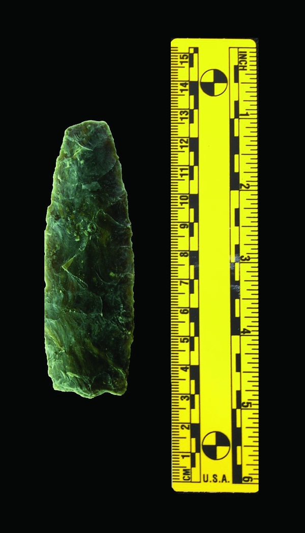
FIGURE 1. Folsom preform from Big Black site, North Dakota. Photo courtesy of Robert Lassen.
Control in experimental archaeology can be difficult to maintain in a project due to the nature of the materials used in the experimental process. Some questions about lithic production are challenging to examine because of the heterogeneity of naturally occurring raw materials such as agate, chert/flint, jasper, obsidian, and quartzite. These raw materials typically contain internal structural differences in the form of cracks and inclusions (Luedtke and Meyers Reference Luedtke and Meyers1992). Even raw materials from the same outcrop can have textural, size, and fracture toughness differences. These factors can create different sets of debitage during the reduction process and may require alternative approaches and/or skill levels to reduce to the same final form (see Figure 2; Rezek et al. Reference Rezek, Lin, Iovita and Dibble2011). There is utility to being able to isolate and control as many variables as possible in an experiment to observe a specific phenomenon (Bernard Reference Bernard2006; Gerber and Green Reference Gerber and Green2012; Klaus and Kempthorne Reference Klaus and Kempthorne1993).

FIGURE 2. Set of errors that would be difficult to re-create exactly using traditional experimental knapping techniques.
For flintknapping experimentation, in particular, the ability to record and reproduce the incident form can potentially answer questions concerning skill level at some stages in the reduction process. There could be many opportunities to explore the stages of reduction found at lithic workshops, such as at the Clovis-period workshop found at the Gault site (Bradley et al. Reference Bradley, Collins, Hemmings, Shoberg and Lohse2010). Additionally, precision control can provide discernment of the subsystems that interact with lithics, namely, antler, bone, and wood (Bello et al. Reference Bello, Parfitt, De Groote and Kennaway2013). This precision control may allow us to observe how various subsystems create different flake patterns and debitage at critical stages in terms of those materials that react similarly to porcelain.
The criteria for knapping are met when using porcelain, as it can be flaked conchoidally as well as being isotropic, brittle, and elastic. However, even the use of porcelain must be employed with caution, per the following:
While porcelain may be usefully applied in most experiments, there are some occasions where it cannot be substituted. For example, experiments investigating the properties of specific material types, such as the effects of heat treating upon various flints, can only be conducted using those specific materials. While the fracture properties of porcelain are similar to flint, it is not a perfect replica of any individual material type, which can be highly variable [Khreisheh, Davies, and Bradley Reference Khreisheh, Davies and Bradley2013:44].
The problem encountered by many researchers exploring other materials is the difficulty in creating a consistent starting point for experiments. In the past, the process has relied on making simple forms and pressing either porcelain clay or slumping glass into a mold (Dibble and Rezek Reference Dibble and Rezek2009). This produces several problems. While these forms are very useful for creating a supply of raw material, they cannot provide the detailed surface morphology required to create a standard from any stage in the knapping process—that is, other than a simple form. In fact, it has been stated that “because each core surface varies in an infinite number of ways due to its own, unique, reduction history, it is virtually impossible to design experiments with cores having identical surface characteristics” (Rezek et al. Reference Rezek, Lin, Iovita and Dibble2011:1346). Furthermore, the method described here can anticipate the shrinkage of the ceramic slip material and adjust the model appropriately. Thus, the method presented here with porcelain slip employed as a medium can allow for highly detailed replication of surface characteristics.
MATERIALS
The methods presented here used both a µ-CT scanner and a scanning arm to record the artifact form for comparative purposes; two 3-D printers, also used for comparative purposes; numerous plaster molding techniques; and finally, casting, production, and firing of the artifact form from several porcelain slips of different firing temperatures. The plaster used for the production of the molds was a generic USG No. 1 pottery plaster. The porcelain slip used was a Cone 10 high-fire porcelain that is completely vitrified at 1,340°C (2,444°F). The porcelain used adheres to the industry standard composition of 25% pure kaolin, 25% ball clay, 25% feldspar, and 25% flint. Early experiments used a Cone 5 porcelain slip that was used for the production of doll faces; however, it failed to capture surface details and was prone to a greater incidence of step fractures. All of the porcelain casts produced for this project were fired in a Cone 10 digital electric kiln.
The properties of Cone 10 porcelain are comparable to those of other knappable materials as shown in Table 1. Porcelain-like materials were used in prehistory, such as porcellanite, fine quartzites, novaculite, and others (Bamforth Reference Bamforth2006; Etchieson and Trubitt Reference Etchieson and Trubitt2013; Fredlund Reference Fredlund1976; Morgenstein Reference Morgenstein2006; Saul Reference Saul1969). Even today, many modern flintknappers use what is often called “johnstone,” or discarded toilet bowl porcelain, to knap highly complex forms (Whittaker Reference Whittaker1994:68). Australian Aborigines were known to climb telegraph lines to retrieve porcelain insulators in the late nineteenth and early twentieth centuries, as well (Harrison Reference Harrison2006).
TABLE 1. Fracture Toughness Values of Quartz-Based Materials.
Values for raw and heated Edwards Plateau chert fracture toughness were experimentally derived using a Vickers microhardness tester and a universal testing machine (Speer Reference Speer2010:166). The other fracture toughness values and grain morphology were derived from multiple sources, and the values for porcelain in Table 2 are derived from multiple tests of the same porcelain composition as in this experiment, also fired to 1,340°C (2,444°F; Bragança and Bergmann Reference Bragança and Bergmann2003; Carty and Senapati Reference Carty and Senapati1998; Wood and Weidlich Reference Wood and Weidlich1982).
TABLE 2. Fracture Toughness of Porcelain with Same Composition.

Source: Adapted from Bragança and Bergmann Reference Bragança and Bergmann2003:804.
METHODS
The primary objective of this research is to provide a method to re-create exact stages during the reduction process as well as to create unlimited, accurate experimental replicas. Even when a researcher uses a glass or porcelain preform, after the first strike, the experiment deviates due to individual skill and circumstance. The secondary objective of this research is to provide a method to engage the archaeological record directly by exploitation of artifacts themselves without damage. In order to re-create the same morphology of the artifact form at any point in the reduction process, this “how-to” method is presented below in several steps. Ten Folsom chert preforms were created by an expert flintknapper for the major flintknapping experiment that this method was designed to demonstrate. The preform used to document the process is presented in Figure 3.
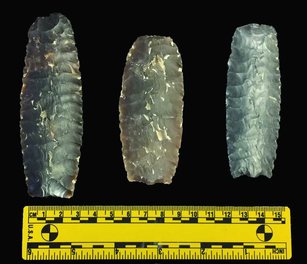
FIGURE 3. Folsom chert preform replicas; the preform on the right is used to describe the method given here. It is made from a black variety of Edwards Plateau chert.
Scanning and Printing
In order to begin the process, first a 3-D scan of the lithic artifact was recorded using a µ-CT scanner (also used to scan for internal material flaws). A scan arm or other 3-D scanner may also be used for this 3-D scan process with appropriate resolution for specific research questions. The µ-CT scanner has an accuracy of submicron levels, while the scan arm used had an accuracy of ±25 µm (0.001 inches). This difference represented a trade-off between speed of scan and accuracy. The µ-CT scanner requires a specialized operator and can take several hours to get high-quality scans. Additionally, the cost of the µ-CT scanner is nearly 10 times the cost of the scan arm. For the µ-CT scanner any format can be exported directly, and there is little to no postprocessing. The detailed models are merged using proprietary software, and export is fairly simple.
The maximum settings of the scan arm allowed for optimal capture of surface features. The scan arm was used for early-stages recording of the artifact shown in Figure 3 before trying other methods. The scan arm used has a rapid scan rate of 280 frames per second at around 2,000 points per line (or 560,000 points per second), with an accuracy of ±25 µm. The scans were imported into a 3-D metrology software program, and then scans from each pass were grouped. Both sides of the model were prealigned and then oriented and meshed. The alignment of the model was optimized using overlapping scans, and a point cloud was produced using proprietary software. A polygonal model was then rendered from the point cloud data. The polygonal model was cleaned; holes were filled as necessary, and/or areas not captured were rescanned. For the model presented, the scans took approximately 10 minutes, while the postprocessing took around an hour and a half.
The model data from the scans performed by both instruments were transferred to two different 3-D printers. Each model was printed in proprietary materials that come from a family of rigid photopolymers that provide excellent detail visualization, durability, and strength. The technique used to print the models was PolyJet 3-D printing. This is similar to inkjet document printing, but instead of jetting drops of ink onto paper, the 3-D printer jets layers of liquid photopolymer onto a build tray and cures them with ultraviolet light. The layers build up one at a time to create a 3-D model at a maximum resolution of 16 µm (0.0006 inches). The models were printed in several varieties of print material at maximum settings to determine which had the appropriate characteristics and resolution for mold-making. It became evident that most of these print mediums could not reach the appropriate level of resolution. It was determined that a clear, even-dispersing photopolymer, which simulates a standard plastic transparent material, was ideal. Fully cured models can be handled and used immediately, without additional postcuring.
The total printing time for the Folsom preform was 6 or 11 hours depending on the model of 3-D printer used. There was no noticeable difference in the print quality between the two printers other than the time it took to build. The time difference is likely due to the size of the build trays. The smaller printer had a build tray of 294 × 192 × 148.6 mm, and the large printer had a build tray of 490 × 390 × 200 mm. Therefore, the larger of the two printers would take longer to sweep across the build tray each time.
Molding and Casting
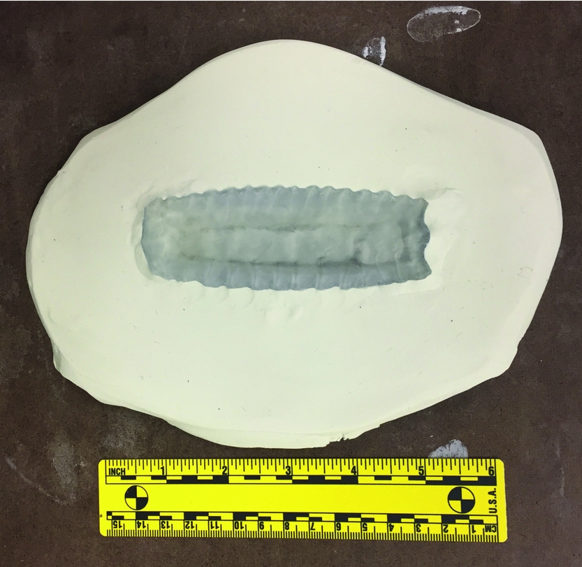
An issue that had to be resolved in order to obtain ~100% accuracy of the porcelain casts was that the porcelain used in this method shrank at a rate of ~14.5% when dried and fired. In order to overcome this, it was necessary to print out a 3-D model ~116.96% the size of the original artifact. For the initial mold production, the 3-D model was encased in clay up to the midline of the 3-D biface model (see Figure 4). Key impressions were made to align both sides of the mold. The 3-D model and clay were then coated with a release agent. The clay base was enclosed in cottle boards (see Figure 5). A fine and sifted plaster was mixed with water and poured over the top of the 3-D model. After the plaster dried, the mold was released from the cottle boards and separated from the model.

FIGURE 4. 3-D model encased in clay up to the midline. An area was hollowed out to allow ideal fit, and a small bead of clay was laid below the model for support.

FIGURE 5. 3-D model enclosed in cottle boards with a release agent sprayed on the surface.
For the second stage of mold production, the first half of the mold was flipped over, and the 3-D model was seated in its negative space. The 3-D model was again coated with a release agent as well as the plaster mold. Both were enclosed in cottle boards, and mixed plaster was poured over the surface. After the plaster dried, the second half of the mold was released from the cottle boards and separated from the model. After both sides of the plaster mold were fully dried and cured, casting could begin.
Casting and Firing
Both sides of the plaster casts of the 3-D model were joined together and held tightly with large rubber bands. A fine Ferro-filtered Cone 10 porcelain slip was mixed and poured into the mold fill hole (~6 mm) that was drilled in the opposite side, along with a small (~2 mm) air hole (Figure 6). There are several options available for the filling of a mold. A cone-shaped piece of clay can be formed at the beginning of the mold-making process and filled from one end, or a hole can be drilled into the plaster on whichever side that will not be (or will be least) affected by experimentation. For larger objects, the cone fill hole appears to work better. For smaller items, the drill method seems to work better and has fewer issues of cavitation of the slip and air pockets being trapped in the form. These small fill holes can easily be cleaned up and blended in by hand on flat surfaces of the original. This depends on the specific experiment at hand. The fill hole must be topped off, as the moisture is absorbed by the plaster.
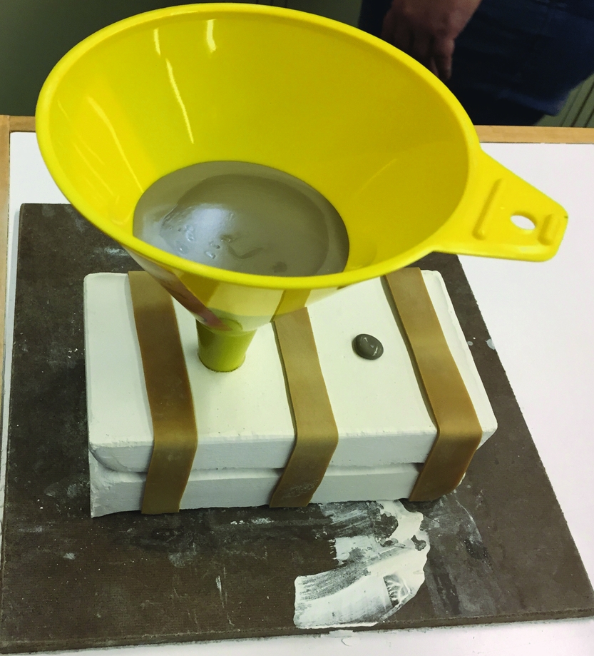
FIGURE 6. Mold being filled with porcelain slip. Note the air hole at the right in between rubber bands.
After sufficient drying was allowed, the mold was opened carefully, and the porcelain cast was removed and allowed to fully dry. In between castings, the plaster must be allowed to dry before proceeding. After the porcelain casts were bone dry, they were then loaded into an electric kiln and fired to Cone 10 (1,340°C [2,444°F]). After the porcelain casts cooled, they were ready to be knapped for experimentation.
RESULTS
Lithic replication experiments produce tools and debitage that may be the result of individual variation and raw material inconsistencies. The method presented here can provide new and exciting avenues of research to explore how and to what extent those variations and inconsistencies affect not only experimental results but also the tools and debitage of the archaeological record. The next question that arises is, how accurate is the porcelain replica in comparison with the original artifact? To answer this question, it was necessary to return to using the 3-D scanner. Scans of the artifact and scans of the porcelain replica were both taken and processed. These two scans were then imported into a proprietary 3-D software program that allowed for reverse engineering of parts and comparison of production models. The results are shown in Figure 7.

FIGURE 7. Results comparing the original artifact with an early porcelain cast. The base model is the original artifact, and the color variation is the difference of the porcelain replica. The green color is nearly exact to the original.
The postanalysis of the method was extremely useful because it highlights certain processes that were going on inside of the plaster mold. The 3-D deviation in Figure 7 represents high spots shifting toward the red end of the spectrum and low spots shifting toward blue and purple. The maximum deviations for this first model overall were 0.8540 mm and −0.9416 mm. The standard deviation was 0.2192 mm, with average deviations of 0.1065 mm and −0.2806 mm. What this illustrates is that the mold was not dry enough in some areas as opposed to others, which highlights the need for a completely dry plaster mold prior to casting. In addition, it also shows that the fill hole needed to be coated in wax prior to casting, as it was removing too much moisture from the porcelain. A postanalysis is highly recommended for improving the accuracy of final casts.
DISCUSSION
The fracture properties of Cone 10 porcelain make it an ideal (and cheap) substitute for other materials (see Table 1). As mentioned, Cone 10 porcelain is brittle, elastic, homogeneous, and isotropic and fractures conchoidally (Khreisheh, Davies, and Bradley Reference Khreisheh, Davies and Bradley2013). Many new research topics can be explored with this method in experimental archaeology. The precision with which every step can be documented, replicated, and tested an unlimited number of times can potentially allow new insights into difficult experimental studies in stone tool production. Skill level can be assessed among knappers more accurately as raw material constraints are removed; various steps or stages can be focused on, and there is no lack of raw material. It is possible using this method to essentially “pause” at a step and use multiple approaches to remove a critical flake, such as a fluting or channel flake. At any stage in the process the knapper can stop, scan and print the experimental form, make porcelain casts, and then see how different techniques alter the morphology of the form (see Figure 8). The specific research question can be answered from many different approaches. This method offers another tool for experimental flintknapping researchers to use in conjunction with other techniques.

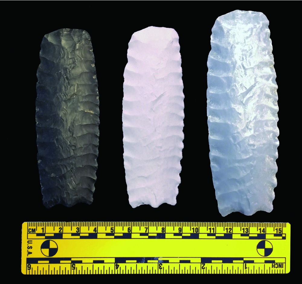
FIGURE 8. From left to right: original chert Folsom preform; porcelain replica; and 3-D print at 116.96% the size of the original.
CONCLUSIONS
There are several drawbacks to achieving the same quality of results for the methods shown. The first is that in order to achieve the optimal level of resolution for each reproduced lithic artifact, there is a high initial investment in equipment. The initial investment in a 3-D scanner may be anywhere from ~$100,000 to $1.2 million, and the printer can cost between $60,000 and $300,000. Cheaper 3-D scanners can be used, but this depends on the requirements of the experiment. In addition, the learning curve required to produce consistent and accurate molds and casts can be challenging. For some lithic forms there may be a serious issue of air pocket inclusion and cavitation of the porcelain slip in the mold. Further, the drying time for the porcelain casts is approximately one–two weeks depending on thickness.
There are several solutions to all these drawbacks. A scan and model made of an artifact or experimental piece can be created by sending it to a company that specializes in 3-D scanning and printing. These will need to be carefully scrutinized to make sure that the optimum settings and materials were used for scanning and printing. For example, when the scan and print settings are above 120 µm, the flake arrises on the models become rounded off and not sharp to the touch, as would be felt on a lithic artifact. The methods presented here aim to assist researchers in answering questions requiring large sample populations and accurate, knappable copies of artifacts.
Acknowledgments
I would like to acknowledge and thank the Department of Anthropology, the College of Arts and Letters, and Dean Kandi Turley-Ames at Idaho State University for their purchase of the 3-D printer used in this research and the start-up funds that enabled the purchase of supplies. I would also like to acknowledge and thank all of the staff at the Grady Early Forensic Anthropology Laboratory at Texas State University for their assistance using the µ-CT scanner and other resources. I thank Jesse Pruitt and Robert Schlader at the Idaho Virtualization Laboratory for assisting me with scanning and processing models and the students who assisted me over the course of this project with mold-making and casting, including Kayla Fuhrman, Daniel Parker, and Shanda Putnam. No permits were required for this work.
Data Availability Statement
All relevant data are contained within this essay.