


1. INTRODUCTION
Pedestrian positioning is a difficult challenge since users typically spend most of their time indoors. GNSS signals are typically unavailable inside buildings due to the heavy attenuation caused by building materials, or are inaccurate due to multipath. This fundamental problem with GNSS signals means that it is necessary to look to other technologies to either augment or replace GNSS signals when navigating indoors. Furthermore, the construction of typical buildings with a lot of small rooms makes adding infrastructure systems such as UWB and RFID a difficult and potentially expensive task that is unlikely to be practical when navigating over wide areas.
On the other hand, indoor pedestrian navigation using inertial measurement units (IMUs) and a computer processor (collectively termed as Inertial Navigation System or INS) has the advantage that no infrastructure is required and, once initialised, the system is totally self-contained. The sensors (normally three accelerometers and three gyroscopes) have the potential to be small, low power, accurate and inexpensive due to the advances in Micro-electromechanical Sensors (MEMS) technology. However, the reality is that the performance of low cost MEMS technology is still relatively low and as a result, their use for positioning applications is limited, unless frequent measurements from external sensors or technologies are available.
One recent idea that has advanced the use of MEMS IMUs for pedestrian navigation is the notion of attaching the IMU to the pedestrian's shoe (Stirling, Collin et al. Reference El-Sheimy, Shin and Jiniu2003; Foxlin Reference Foxlin2005; Beauregard Reference Beauregard2007; Godha and Lachapelle Reference Godha and Lachapelle2008; Jadaliha Reference Hide, Pinchin and Park2008; Rajagopal Reference Rajagopal2008; Hide Reference Collin, Mezentsev and Lachappelle2009; Feliz et al. Reference Feliz, Zalama and Gomez2009; Robertson et al. Reference Robertson, Angermann and Krach2009). This results in the substantial advantage that the foot has to briefly be stationary while it is on the ground. During this period, Zero Velocity Updates (ZVU or ZUPT) for example in (Grejner-Brzezinska et al. Reference Grejner-Brzezinska, Yi and Toth2001), can be used to correct the user's velocity. Furthermore, if the ZUPT measurements are used in a Kalman filter, for example in (Foxlin Reference Foxlin2005; Godha and Lachapelle Reference Godha and Lachapelle2008), they can not only be used to correct the user's velocity, but also help restrict the position and attitude errors and estimate the sensor bias errors. The frequent use of ZUPT measurements consistently bounds many of the errors and as a result, even relatively low cost sensors can provide useful navigation performance.
However, there remain two significant problems with MEMS IMU pedestrian navigation. Firstly, the initial position, velocity and attitude have to be obtained. For a stationary IMU, the velocity, roll and pitch can be set, where roll and pitch are obtained by comparing the accelerometer output to the local gravity vector. An initial estimate of the gyro biases can be initialised if the IMU is non-rotating. However, the main problem is that position and heading need to be obtained from external sensors. Typically, position is initialised using GPS, although the ability to do this will depend on whether the user is located in an area where GPS is available, and if it is, whether it is accurate. Heading also needs to be initialised since low cost gyros are unable to measure the rotation of the Earth which is used to initialise heading for much more expensive sensors. Instead heading must be obtained from an external sensor such as a magnetometer which is undesirable since magnetic disturbances can cause significant errors.
The second significant problem that remains is heading drift during navigation. Heading drift still remains despite using ZUPT measurements in the Kalman filter since the heading error is unobservable. Observability is the ability to determine a state from a given sequence of measurements, and in the situation of using ZUPTs to aid a low cost IMU, it is not possible to estimate the heading error using only these measurements. This causes a significant issue since there then becomes a requirement to use heading measurements from external sensors. Typically magnetometers are used, however as previously mentioned, their measurements are often unreliable when navigating in environments such as indoors where there are significant magnetic disturbances. Instead, it is desirable to use measurements from other systems or methods to control heading drift.
This paper develops a novel and effective algorithm for generating heading measurements from basic knowledge of the orientation of the building in which the pedestrian is walking. The idea is based on the assertion that most buildings are constructed with a rectangular shape. Within this shape, most rooms and corridors are constructed of smaller rectangles which constrain the direction a pedestrian can walk throughout the building to one of four headings. We use the term Cardinal Heading in this paper to describe the four possible headings that the user is likely to walk in most of the time. Although by no means all buildings are constructed in this way, a good deal of buildings are. Manhattan, New York is a good example of a large number of buildings all aligned in a single direction as in Figure 1 (Left), and most of the buildings in this area will have rooms and corridors aligned with a heading of either 29·4°, 119·4°, 209·4° or 299·4°. These four headings can be represented by a single angle since the others are simply offset by 90°. A simple method for deriving this heading is to use the distance and angle measurement tool in the Google Earth application (Butler Reference Butler2006). On a smaller scale, Figure 1 (Right), shows part of the University of Nottingham campus where most of the buildings are aligned in one of two orientations. Furthermore, when considering buildings on an individual scale, the majority of buildings conform to this concept.

Figure 1. (Left) Buildings in Manhattan, New York. (Right) University of Nottingham campus.
This paper describes an algorithm for using simple heading information derived from maps to restrict the heading drift that occurs when using a low cost foot mounted IMU for navigation. The heading information can be derived quickly and potentially in an automated manner, using free maps or aerial images without the need for detailed internal maps of the building. In some situations, large areas can be covered using a single heading measurement (such as parts of Manhattan), whereas other areas will require more detailed resolution (such as European cities). We are able to show that the novel use of such heading measurements is able to significantly reduce the drift of IMU-only navigation without the need for measurements from GPS, compasses or other sensors once the system has been initialised. It is demonstrated that position accuracy can be maintained below 5 metres for significantly long periods of up to 40 minutes. These kinds of accuracies were previously only achievable using high accuracy inertial sensors, but even these devices still need zero velocity or other sensor measurements to control position drift. The accuracy obtained is therefore comparable with (Collin et al. Reference El-Sheimy, Shin and Jiniu2003) which used a high performance ring laser gyro with drift less than 1 degree per hour. In his system, the error in position was calculated to be just 5 metres in over 40 minutes of walking trial inside a building. The algorithm is simple to implement, low in computational resource, works in real-time, and can be easily scaled to large areas even if the map information is derived manually. Furthermore, it is demonstrated that the algorithm is robust to short periods where the pedestrian will walk in directions not consistent with the building. In this paper, the proposed system is called Cardinal Heading Aided for Inertial Navigation (CHAIN) system.
Results from real data trials at a public hospital show the possibility for various future applications that could help people to navigate in non-GPS environments. Such possible applications include patient's movement monitoring by doctors in hospital, or navigating visitors around the hospital. The system could be used for guidance for blind people or people with visual difficulties. Another possible application would be for leisure activities such as shopping, tourism and virtual gaming. Indeed there are many more possible future applications that can be realized as a result of our proposed algorithm. The algorithm is based on sensors that are already available in mobile devices which indicates that the overall cost of the system could be relatively inexpensive. With the current achievable accuracy shown in this paper, it is expected that the proposed approach can become a stepping-stone for others to utilize it for their own developed application.
2. ALGORITHM
The algorithm that has been developed is based mainly on traditional inertial navigation equations, with errors controlled through the use of measurements applied using a Kalman filter. The following sections give an overview of this approach, followed by a detailed description of the new CHAIN algorithm.
2.1. Inertial Navigation
Low cost IMUs typically consist of micro-electromechanical gyros and accelerometers which are ‘strapped’ down to the body of interest: in our case, a foot. Hence the outputs are measured in the body frame rather than the global frame. After determination of initial position, velocity and attitude during system initialisation, the gyro's angular rates are integrated once to get the attitude of the system. Using this known orientation, the acceleration outputs from the three accelerometers are transformed into our desired frame of reference. The navigation frame is chosen as our reference frame because we are interested in knowing the user position in the geodetic coordinate system. Subsequently after correcting for local gravity, these acceleration outputs are then integrated to get the velocity, and integrated again to get the position. Normal strapdown navigation equation such as in (Titterton and Weston Reference Titterton and Weston2004) are used to resolve and update the position and attitude of the IMU. Velocity in the navigation frame is computed by numerically integrating the following differential equation:
where v n is the velocity in the local (North, East, Down) navigation frame; C bn is the rotation matrix that transforms measurements from the IMU in the body frame, to the navigation frame; f b is the accelerometer measurement in the body frame; ωien is the rotation rate of the Earth in the navigation frame; ωenn is the transport rate of the navigation frame and g n is the gravity vector in the navigation frame. The middle terms can be ignored since low cost IMUs are not capable of measuring Earth rotation and also navigation is done with a small velocity. The attitude of the IMU is maintained using the following differential equation:
where C bn is the skew-symmetric matrix of body frame rotations corrected for Earth rotation and transport rate; see (Titterton and Weston Reference Titterton and Weston2004) for further details of strapdown navigation algorithms.
The position and attitude of the system can then be regularly updated by numerical integration of the IMU output. However, due to its low cost specification, low cost IMUs contain errors such as biases and noise. After only short periods of time, due to the numerical mechanisation, these errors accumulate and cause significant position and attitude errors. A Kalman filter was used to estimate these errors and will be explained further in the following section.
2.2. Kalman Filter
The Kalman filter is widely used for optimal state estimation and details about it can be found for example in (Simon Reference Simon2001; El-Sheimy Reference Jadaliha, Shahri and Mobed2006; Hide et al. Reference Hide and Moore2007). For this paper, the state vector that was used is shown below:
where δp is the vector of latitude, longitude and height errors; δv n is the vector of navigation frame velocity errors; δω is the vector of attitude errors (roll, pitch and yaw); δg b is the vector of gyro bias errors and δa b is the vector of accelerometer bias errors. The filter is used in feedback form which means that errors calculated from Kalman filter are used to correct the inertial sensor measurements and navigation parameters. Only the forward Kalman filter is considered in this paper since our focus is real-time use, but theoretically, using Kalman filter smoothing such as RTS algorithm should give much better results (Hide and Moore Reference Hide, Botterill and Andreotti2005).
2.3. ZUPT and Observability
As explained in section 1, observability means the ability to estimate certain parameters in Kalman filter. This can be illustrated by considering a static IMU. For example, if an incorrect roll or pitch measurement is computed, this will result in the gravity vector being incorrectly removed from the accelerometer measurements. This results in a residual acceleration error, which will result in a velocity error after numerical integration. Therefore, by using ZUPTs in the Kalman filter, the error can be controlled. However, if the heading of the IMU is changed, this does not affect the velocity and therefore ZUPT measurements are unable to restrict the error. The relationship between velocity errors and attitude errors in Local Level Frame (Godha and Lachapelle Reference Godha and Lachapelle2008) is shown in equation (4):
![\left[ {\matrix{ {\delta \dot{v}_{N} } \cr {\delta \dot{v}_{E} } \cr {\delta \dot{v}_{D} } \cr} } \right] \equals \left[ {\matrix{ 0 \tab { \minus f_{D} } \tab {f_{E} } \cr {f_{D} } \tab 0 \tab { \minus f_{N} } \cr { \minus f_{E} } \tab {f_{N} } \tab 0 \cr} } \right]\left[ {\matrix{ {\delta \varphi } \cr {\delta \theta } \cr {\delta \psi } \cr} } \right] \plus \left[ {\matrix{ {\delta v_{N} } \cr {\delta v_{E} } \cr {\delta v_{D} } \cr} } \right]](https://static.cambridge.org/binary/version/id/urn:cambridge.org:id:binary:20151022041307601-0049:S0373463310000573_eqn4.gif?pub-status=live)
where f is the force in the body frame (including gravity) and δϕ, δθ, δψ are the roll, pitch and yaw errors respectively. During ZUPT, the horizontal forces in the local level frame are essentially zero and specific force f D in downward direction is approximately close to the negative gravity constant. Therefore from this equation, it can be seen that the velocity errors in North and East directions are only related to errors in roll and pitch attitudes via a specific force f D in downwards direction. This means that during ZUPT period, the dynamic change in horizontal velocity is proportional to the change in roll and pitch errors. Improving the velocity estimation through ZUPT means that roll and pitch errors are improved as well but not the heading errors and this has actually motivated the idea in this paper.
2.4. Cardinal Heading Measurements
As described in the introduction, cardinal heading measurements are obtained by extracting the principle heading of individual buildings on a map or aerial photo. Assuming that a user typically walks along these four directions as they navigate the building, the heading information can be used to update the INS heading. The algorithm relies on the assumption that the remaining position error after applying ZUPTs is mainly a result of heading error. This is a reasonable assumption since ZUPTs are able to control most of the significant error sources apart from heading error (and z-axis gyro bias drift if the IMU is mounted with z mainly pointing down). Based on this assumption, we compute the direction of a step that the pedestrian has walked from the INS using the following equation:
where ΔE and ΔN are the changes in East and North-axis positions over one step. This heading measurement is based only on the change in position caused by a single step, and therefore ψstep not only consists of the true heading plus drift, it also consists of other small errors from inertial navigation.
If we assume that the user is walking in one of the four cardinal directions, an estimate of the heading error can be derived by forming the observation:
where ψcardinal is the cardinal heading derived from a map and resolved in the correct quadrant. The angle is resolved in the correct quadrant by comparing ψstep with four possible cardinal building headings. If the difference is less than a predetermined threshold, the measurement is applied in the Kalman filter. Conversely, if the difference is exceeded, no update is applied. This accommodates periods where the user is not walking in a direction consistent with the building such as around corners. However, it does identify an important issue with the algorithm where it is necessary that the IMU is maintaining sufficient heading accuracy to perform the threshold step correctly. This is considered further in the results section of this paper.
Another issue that should be considered is that pedestrians don't walk exactly in straight lines and therefore an appropriate measurement noise should be used to accommodate this. It should also be noted here that the heading error measurement does not relate directly to the physical attachment of the IMU which can be mounted in any orientation on the user's foot. This is significant because it does not matter if the user is walking sideways or even backwards for the algorithm to work.
3. FIELD TRIALS
Three field trials were undertaken to test the proposed approach. The first trial involved normal walking around a typical football pitch with an RTK system to act as a position reference to evaluate the accuracy of the foot mounted IMU. For the second and third trials, a normal walking and irregular walking were undertaken respectively in a typical indoor environment at Queen Medical Centre (QMC) Hospital, Nottingham within a built up area of about 65 000 m2. There was no ground reference used in QMC trial due to difficulty to have such a reference system inside buildings, hence the result is discussed using Google Earth aerial imagery as a coarse approximation. Total walking distance is approximated as typical walking velocity of 1·5 m/s multiplied by the total time of the trial.
3.1. Equipment
For all trials, a MicroStrain 3DM-GX3-25 IMU was used which has typical technical specifications of a low cost IMU grade with a dimension of 44 mm×25 mm×11 mm, weighing only 11·5 g. The accelerometer bias stability is quoted as ±0·01 g, and for the 300deg/s model, the gyro biases are specified as ±0·2deg/s. The particular IMU used has a limit of 1200deg/s for angular rotation and 18g for acceleration, which is sufficient for the walking trial. This is because the typical rotation of a pedestrians foot is typically between 600deg/s to 900deg/s while walking. The IMU measurements were synchronized with GPS time using IESSG Precise Time Data Logger (PTDL) which is able to accurately timestamp the serial data from IMU and record it using an SD card. The GPS time stamp is only recorded for the purpose of synchronising the IMU with GPS so that a comparison can be made between the CHAIN and GPS solutions. Theoretically, if autonomous navigation is sought only in indoor environment without any comparison (assuming initial position is known), the GPS time stamp is not needed and it can be replaced by IMU's internal clock. Figure 2 shows example of the system setup used for field trials. The Backpack contains the PTDL, a 12V battery and u-Blox ANTARIS 4 High Sensitivity GPS receiver and a Leica GPS 1200 Real Time Kinematic system (RTK) while the IMU is shown to be mounted on foot.

Figure 2. Example of system setup.
The initial position for the IMU was estimated from the GPS position (which in practice would assume that navigation would start in a well received GPS signal area). The initial roll and pitch of the IMU was calculated during a short stationary period (1 second) by differencing the accelerometer measurements with the local gravity vector. The heading was initialised manually, but it is expected that a one-off magnetometer reading could be sufficient to initialise the algorithm. Normal strapdown navigation equations were used to resolve and update the position and attitude of the IMU. Once it has been initialised, the system computes its position relative to the initial position. Measurements were then post processed using the University of Nottingham's POINT (Position and Orientation Integration) software (although the algorithm could still be used in real-time). The software was designed specifically with the purpose of allowing easy integration with measurements from external sensors. Details of POINT software are described in (Hide, Moore et al. Reference Hide and Moore2007; Hide, Pinchin et al. Reference Hide, Moore and Hill2007).
3.2. Trials Description
The following sections describe trials that have been conducted to test the new algorithm.
3.2.1. Football Pitch Trial with RTK Reference
Since there was no reference system available that could work in indoor environment to verify the accuracy using the proposed algorithm, an outdoor test was necessary to emulate the indoor environment. The outdoor test was conducted with a 40-minute normal walk on a football pitch at the University of Nottingham. The football pitch is approximately 95 m×55 m in dimension with a typical white boundary line. The user walked ten circuits around the boundary line of the pitch so that the user was walking approximately in straight lines apart from at the corners, emulating a walk around corridors in a building. The RTK system was also used in this trial as a ground reference with an accuracy of approximately 2 cm (figure was given by the RTK system) throughout the whole trial.
Figure 3 (Left) shows the comparison of the two trajectories. The blue trajectory represents the low cost IMU using the proposed approach while the green trajectory is the reference trajectory from the RTK solution. Figure 3 (Right) shows the position difference of the CHAIN solution compared to the RTK solution. It should be noted that the difference also includes the non-constant offset of the IMU moving on the user's foot relative to the GPS antenna on the user's back which is shown by the smaller high frequency oscillations. The maximum horizontal difference is less than 5 metres with a standard deviation of 1·7 m and 1·2 m for North and East respectively. For the North and East errors, the oscillations that occur are a result of a full round of walking (there are 10 peaks which are equivalent to 10 rounds of walking). This appears to be a result of the IMU solution resulting in slightly shorter distance measurements than the RTK truth. However, the height error is still prominent with maximum height error of about 11 metres after 40 minutes of walking.

Figure 3. (Left) Trajectory of walking on football pitch boundary line. (Right) Position innovation of CHAIN solution against RTK solution.
After a free inertial navigation of approximately 40 minutes in duration and 3000 metres in distance, the absolute position error is about 3·5 metres, or about 0·12% of the total distance travelled. This is a significant improvement in the use of low cost MEMS positioning which demonstrates the effectiveness of the CHAIN algorithm. In fact, such performance is difficult to achieve even with high quality inertial sensors, unless they can be foot mounted. For example, even navigation grade inertial sensors have a typical drift of approximately 2 km per hour, so unless regular measurement updates (such as ZUPT) can be applied, the performance is not comparable to the low cost CHAIN solution.
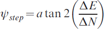
To demonstrate the application of the heading updates, Figure 4 shows the Kalman filter innovation for the heading measurements. The innovation is the difference between the INS derived step heading, and the building heading. The difference comprises of the INS heading error, other small INS drift, and also the variation of the user's step in relation to the heading of the building. The standard deviation of heading error is shown to be only 2·1° whilst the maximum heading error is 9·7° (which corresponds to the 10° acceptance threshold). The maximum values probably occur as the user walks around corners and the walking in straight lines assumption is not correct.
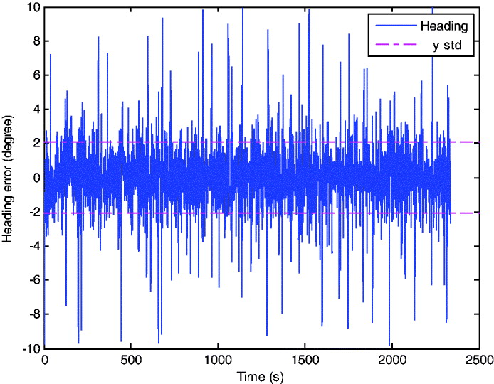
Figure 4. Heading error of CHAIN solution.
3.2.2. QMC Hospital Trial with Normal Walking
A second trial using the low cost IMU was undertaken at Queens Medical Centre Hospital, Nottingham as shown in Figure 5 (Left). This building is selected because it represents a typical building with many straight features. The normal walking trial was done for about 40 minutes with an approximate distance of 3 km. The trial started and ended at approximately the same location as shown by the junction at the right of Figure 5 (Right). The u-Blox GPS receiver was also used for comparison purposes to indicate the performance of a high sensitivity receiver in this building.

Figure 5. (Left) QMC aerial imagery, hospital entrance is at the top of the picture. (Right) Hospital entrance with ‘No Entry’ sign (right) as the start and end location.
Figure 6 shows the trajectory taken during the trial. The green line shows the output of CHAIN system, the red dot marker shows HSGPS output and the red line shows the IMU+ZUPT solution. Although the GPS receiver can track more than four satellites in some parts of the building, no useful comparisons could be made between the GPS solution and the proposed CHAIN solution because of the high multipath measurements (see red dots in Figure 6 (Left)). However coarse analysis using aerial imagery of Google Earth as shown in the figure is sufficient to indicate that the integrated position solution is usually better than 5 m, and typically less than 2 m most of the time with respect to the image. Furthermore, as expected, the heading is always consistent with the building.
Figure 6. (Left) CHAIN solution (green) and HSGPS solution (red). (Right) IMU+ZUPT solution (red) and CHAIN solution (green).)
As mentioned before, there was no ground reference except the freely available aerial imagery of QMC building; hence only rough approximation of the trajectory analysis for Figure 6 (Right) can be done using Google Earth. Nonetheless it does provide a useful insight into the effectiveness of this approach against a standard ZUPT. It is obvious that the CHAIN solution overcomes a standard IMU+ZUPT solution based on the difference between the two trajectories as shown in Figure 6 (Right). In this figure, it is clear that the majority of the position drift occurs as a result of heading drift, hence the motivation for this paper. The difference between the start and end position for CHAIN system is about 2·30 m, approximately only about 0·08% position error from a total walking distance of 3000 m which again is a significant improvement in performance. For the IMU+ZUPT only approach, the difference is about 220 m, approximately about 7% of the total distance and with a significantly corrupted heading solution.
3.2.3. QMC Hospital Trial with Irregular Walking
A third trial for a period of 15 minutes was undertaken to simulate the irregular walking behaviour with the same start and end location. This is to examine the performance of the algorithm when the walking in straight lines assumption within the building does not necessarily hold true. Four different types of walking pattern were analysed and alphabetically depicted in Figure 7 as A, B, C and D with their pattern descriptions.

Figure 7. Areas of irregular walking in QMC hospital. [A]. Entering QMC through the main entrance (from upper right corner) to a convenience shop (bottom middle), walking into two aisles before coming out from the shop. Walking into another shop (top centre), did one round before coming out through the main entrance to the starting position. [B]. After cornering (top), a ‘zig-zag’ walk was undertaken.[C]. Backwards walk (from left to right). [D]. Walked (from top) to the spiral stairs, down to the lower floor until the end (bottom) and made a small loop around a pillar (bottom). Then walked up to another stairs for three levels (right) and then walked down again to the spiral stairs. Walked up the spiral stairs to the start of walk.
Again there was no ground truth to be used as a reference; instead aerial imagery from Google Earth is used only for visualisation purposes (Figure 8). Red dots in Figure 9 show the times at which cardinal heading measurement updates were automatically applied to the system. With these irregular walking patterns, the start and end position error still gives an error of about 1·25 m, again approximately only 0·1% of the total walking distance of ~1248 m. In this trial, the system also showed robustness for a short period when the heading measurement is not being updated (period where there is no red dot).

Figure 8. CHAIN output trajectory.

Figure 9. From left top corner (clockwise) – Trajectory [A], [B], [C] and [D].)
4. DISCUSSION
In this section, possible areas where the algorithm will possibly not work will be discussed. This is purely based on a theoretical view along with experience of the algorithm already accumulated from multiple field trials. Firstly, continuous walking in circles or non-straight lines for a long period of time is likely to cause a problem for the algorithm. This is because a straight walk check will always return false in the algorithm and as a result, there are no measurements available for the filter to predict the solution. Therefore, during this period, the heading will drift. If the drift is large enough so that the building heading does not remain within the threshold check when the user does start to walk in straight lines again, the algorithm will fail. As shown in the results section in trial 3, cornering for a short period of time has no significant effect on the final solution. In these situations, the algorithm should be robust to short periods of walking in non-straight lines for a few minutes, before the heading drift becomes significant.
Secondly, it is clear that not all buildings conform to the simple geometry of restricting most walking to one of four cardinal directions. In the extreme case, some buildings are built with circular corridors (an example of which can be found at the library on the University of Nottingham's Jubilee Campus) and in this instance, the algorithm is unlikely to improve the INS-only solution. A similar situation will occur when a pedestrian is walking inside a large room where the motion is not constrained to the four cardinal directions. Other less common situations are where a building is constructed with rooms and corridors using more than one possible heading. In this situation, it may be possible to extend the algorithm to include additional headings, although this is likely to reduce the robustness of the algorithm. Another situation is that the internal rooms and corridors may not be aligned with the outside of the building. This would cause a problem since we extract the building heading by using the measurement tool in Google Earth using aerial imagery. If this angle is not the usual angle that people walk inside the building, the algorithm will not work satisfactorily. However, it is by far the most common situation that buildings are designed with a simple construction, such as in this paper, where the algorithm will work well.
A third issue that should be discussed is that as the user walks between buildings, the algorithm will need to change the heading that is used. At the moment, the information is extracted from a Google Earth kml file that contains polygons that have been manually defined. It is necessary that the position remains accurate as the pedestrian walks between buildings, otherwise the wrong heading may be used, and this will result in an unpredictable heading and position error. By using measurements from other systems such as GPS when it is available, we expect to be able to restrict position drift sufficiently in most situations.
A final issue is that we assume the pedestrian is walking continuously without stopping for any long periods. If the user stops, heading measurements will not be available because the algorithm can only compute heading drift when a user takes a step. During this time the heading drift will be unconstrained and, when the user moves again, the heading may have drifted sufficiently that the algorithm will not work. In this situation, it is expected that a heading drift restriction algorithm could be applied where the gyro output is threshold checked and, if the output is within the threshold, a measurement will be used to maintain the heading to the last known heading.
5. CONCLUSION
This paper describes an algorithm for using simple heading information derived from maps to restrict the heading drift that occurs when using a low cost foot mounted IMU for navigation. The algorithm uses the simple notion, that users are typically constrained to walk in one of four cardinal headings due to the way corridors and rooms are typically constructed. The heading of the building can be obtained by taking measurements from maps or aerial images which is simple and fast to extract for even relatively large areas. It is also expected that this information could be automatically derived using, for example, computer vision algorithms in the future. The algorithm has the significant advantage that it is not necessary to derive detailed indoor maps of buildings for it to be effective, as indoor maps are typically not available.
The effectiveness of the algorithm has been demonstrated through analysis of real world data by using the foot mounted IMU approach. Data gathered during experimental tests were used to show its effectiveness as a self contained system without depending on other sensors for measurement updates. It has been shown in this paper that the estimated accuracy in position is below 5 m in 40 minutes walk and about 0·1% of the total distance by using only forward Kalman filter. This approach provides an important leap in autonomous inertial pedestrian positioning by addressing the main problem of heading drift. Importantly, the algorithm is simple to implement, uses little additional processing requirements and has been shown to be robust even in situations where the user walks in different directions and non-straight lines.
Future work will include adding measurements from additional sensors such as GPS when it is available, and potentially a 3-axis magnetometer where it is hoped that the additional building heading measurements can be used to identify good quality magnetometer measurements in areas where there are minimal magnetic disturbances. Other improvements include restricting the heading drift when the user is stationary, and also restricting the vertical position drift by using the fact that most buildings are built with level floors, except for steps. It is expected that the combination of foot mounted IMU, GPS, magnetometer and building heading will enable high accuracy navigation to be maintained for long periods of time using low cost sensors with this efficient and effective algorithm.


