Aim
The main objectives of this study were as follows:
∙ To quantify the catheter displacement in fractionated interstitial high-dose-rate (HDR) brachytherapy.
∙ To assess the dosimetric impact of inter-fraction variation on tumour volume.
Background
It is estimated that there will be 22·2 million new individuals diagnosed with cancer by 2030 worldwide.Reference Ferlay, Soerjomataram and Ervik1 The worldwide incidence of squamous cell carcinoma of the head and neck is more than 500,000 cases per year, and the management of patients with head and neck cancer is complex.Reference Jemal, Murray, Samuels, Ghafoor, Ward and Thun2 The choice of treatment modality depends on the stage and site of disease. Brachytherapy plays an integral role in the management of head and neck cancers and has been described as the first form of conformal radiation.Reference Dale and Jones3 Precise source placement enables delivery of very high doses within the tumour and sufficient dose at the margin between the tumour and normal tissue, ensuring high tumour control. At the same time, only small volumes of normal tissue are irradiated, thus decreasing the normal tissue complications.
Traditionally, treatment planning of brachytherapy was mainly based on radiographs and point dosimetry.Reference Joslin, Flynn and Hall4 The dose distribution was related to the geometry of the catheters. With the newer three-dimensional (3D) treatment planning systems together with computer tomography (CT) imaging, it is possible to obtain a 3D-based dose distribution with reconstruction of the tumour volume and the catheters.Reference Eeva, Krystyna and Geoffrey5 Advanced computerised treatment planning and image-guided delivery systems increase efficiencies and improve outcomes. This is achieved through the placement of a radioactive source within or adjacent to a tumour, using specially designed applicators and remote computer-controlled delivery devices. This allows a tailored radiation dose to be delivered very precisely to the target area. The ability of brachytherapy to deliver high-radiation doses over a short time period means that patients can complete treatment in days rather than weeks required for external beam radiotherapy (EBRT). Brachytherapy is generally well tolerated with a good toxicity profile for many of its applications, largely due to its tissue-sparing approach. The use of imaging techniques such as ultrasound, CT, magnetic resonance imaging and positron emission tomography for treatment planning has led to improved visualisation of the tumour and surrounding organs. The use of multiple imaging techniques can help in improving the treatment-delivery process and allow real-time changes to dose and applicator positioning.
Although brachytherapy continues to be a key cornerstone of cancer care, it is clear that treatment innovations are needed to build on this success and ensure that brachytherapy continues to provide quality care for patients. The dosimetric advantages offered by HDR brachytherapy to the tumour volume rely on catheter positions being accurately reproduced for all fractions of the treatment. However, catheter migration is often observed between fractions.Reference Martinez, Pataki, Edmundson, Sebastian, Bradbbins and Gustafson6, Reference Hoskin, Bownes and Ostler7 This leads to a significant risk of under dosage to the tumour tissue or over dosage to the organs at risk. Correction of catheter migration, thus, becomes more important. Catheter position can change during treatment or between fractions, resulting in shifts of source dwell positions relative to the target structures and organs at risk, and thereby changing the delivered dose.
The positional stability of the catheters and the resultant dosimetric variation over a period of time are studied and presented.
Materials and methods
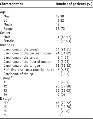
The remote afterloading HDR brachytherapy treatment unit GammaMed iX plus (Varian Medical Systems, Palo Alto, CA, USA) or the Microselectron HDRV3 (Nucletron BV Waardgelder, Netherlands), using single sealed Iridium 192 radioactive source, was used for treatment, and for treatment planning Eclipse (Varian Medical Systems) or Oncentra Master plan (Nucletron, BV) was used. Images for planning were acquired by CT Somatom spirit (Siemens, China). A total of 66 patients were included in this study over a period of 22 months from December 2011 to September 2013. The Demographic details of patients are given in Table 1. The patients were treated after evaluation according to the stage of the disease as per the institute’s treatment protocol, given in Table 2.
Table 1 Patient characteristics

a According to the 7th American Joint Commission on Cancer/Union for International Cancer Control Staging system.
Table 2 Institutional treatment protocol

a Five fractions per week with one fraction per day.
b Two fractions per day with 6 hours gap between the two fractions.
c With spinal shield after 44 Gy.
Abbreviations: EBRT, external beam radiotherapy; HDR, high-dose rate.
Interstitial implant application
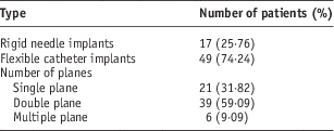
Under general anaesthesia, trocars and hollow needles were inserted as guide tubes in and around the tumour, 1-cm apart, in single or multiple planes through which plastic tubes were threaded. These tubes were then secured by buttons. A patient with flexible catheter implant is shown in Figure 1. Similarly, for rigid needle implant, the sterilised needles with the appropriate length were selected. With the guidance of templates, the needles were inserted into the tissue. The template helped in maintaining proper geometry of the needle placement. The needles were secured by stainless steel buttons (Figure 2). Table 3 gives the characteristics of the interstitial implants.

Figure 1 Patient with a flexible interstitial implant.

Figure 2 Patient with rigid needle implant.
Table 3 Implant characteristics

Imaging and planning
On the 2nd day after implantation, the patients underwent CT scan of the involved region, with a slice thickness of 1 mm. However, for cancer cervix Martinez Universal Perineal Interstitial Template (MUPIT) patients, CT imaging was done immediately after catheters implantation, and treatments were delivered within 1–2 hours. On the CT images, the applicator reconstruction was done, and at the tip of all the applicators a reference point was inserted. The reconstructed catheters in TPS with reference points are shown (Figure 3). These reference points act as tracking tools to monitor the catheter movement between both the plans. The source dwell positions and step size were identified, and accordingly the fine tuning of dose optimisation was carried out by changing the dwell time and weighting for individual dwell positions. In most cases, dwell time was changed to reduce the hot spot or to remove the cold spot. Graphical optimisation was never used. It was ensured that at least 90% of the clinical target volume received the prescribed dose. The dose distribution was generated by TPS using the AAPM TG-43 dose formalism.Reference Nath, Anderson, Luxton, Weaver, Williamson and Meigooni8 Treatment was delivered using the HDR remote afterloading system. On the last fraction, a repeat CT (post HDR) and re-planning were done, and the catheters were removed.

Figure 3 Reconstructed implant with a reference point.
For each patient, planning was done on both pre-HDR and post-HDR images. Pre-HDR and post-HDR images were fused on the basis of the prominent anatomical landmarks close to the clinical target volume, anatomical landmarks that have no positional variation, catheter geometry and template positions.
The step size dwell position and dwell time were maintained the same in both the plans, and only the catheter position was updated in the post-HDR brachytherapy plan. The tip of the catheters where the reference points were inserted gave the co-ordinates in x, y and z axes. The variation in the reference points between the two plans were estimated, which gave the actual displacement in the catheter position in 3D axis. The schematic representation of plan fusion and the reference point analysis are shown in Figure 4. Using the dose–volume histogram (DVH), dosimetric parameters were studied for both the plans and the dosimetric variation was estimated.

Figure 4 Schematic diagram of plan fusion. HDR, high-dose rate.
Plan analysis
The variation in the reference point (3D vector) between the two plans was obtained. This gave the geometrical displacement of the catheters. If there is no displacement of the catheters, it is expected to have the same co-ordinate values in both the plans, which will result in co-ordinate x=0, y=0 and z=0. Any variation or movement in the catheter will have some definite values. The dosimetric variation for all the reference points was also obtained. To estimate the volumetric data, the dose received by 90% of clinical target volume (D90) was obtained from the DVH. The other parameters that were obtained were volumes receiving >150% of the given dose V150%.
Result
For 14 patients with carcinoma of the breast, the displacement in catheter position and dosimetric variation are shown in Figures 5 and 6. For all the patients, the catheter displacement and D90 dose to clinical target volume were <3 mm and 3%, respectively.

Figure 5 Catheter displacements for carcinoma of the breast.

Figure 6 Dosimetric variations for carcinoma of the breast. Abbreviation: CTV, clinical target volume.
For 21 patients with carcinoma of the buccal mucosa, the catheter displacement for 33·33% of the patients was >5 mm (Figure 7). In 38·10% of the patients, D90 dose to clinical target volume was >3% (Figure 8).

Figure 7 Catheter displacements for carcinoma of the buccal mucosa.

Figure 8 Dosimetric variations for carcinoma of the buccal mucosa. Abbreviation: CTV, clinical target volume.
For 21 patients with carcinoma of the tongue, the displacements in catheter position are shown in Figure 9. The catheter displacement for 38·10% of patients was >5 mm. As per DVH data, in 28·57% of the patients, D90 dose to clinical target volume was >3% (Figure 10).

Figure 9 Catheter displacements for carcinoma of the tongue.

Figure 10 Dosimetric variations for carcinoma of the tongue. Abbreviation: CTV, clinical target volume.
The catheter displacement for 10 patients with carcinoma of the cervix (three patients), carcinoma of the floor of mouth (two patients), soft-tissue sarcoma (three patients) and carcinoma of the lip (two patients) are shown in Figure 11. The dosimetric variations are shown in Figure 12.

Figure 11 Catheter displacements for other sites.

Figure 12 Dosimetric variations for other sites. Abbreviation: CTV, clinical target volume.
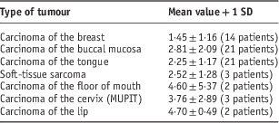
Table 4 gives the details of the mean dose variation in percentage to D90 of clinical target volume.
Table 4 Dosimetric variation in percentage to D90 of CTV

D90, dose received by at least 90% of the volume. Abbreviation: CTV, clinical target volume.
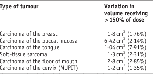
The dosimetric variations to volumes receiving >150% of the prescribed dose are given in Table 5
Table 5 Dosimetric variation to volume receiving 150% of dose

Discussion
A preliminary analysis with 55 patients was carried out and it was concluded that increase in the treatment duration increases inter-fraction error.Reference Saravanan, Reddy, Nagarajan, Parthasarathy and Gunaseelan9 Inclusion of carcinoma of the lip patients in this study provided some new findings that oedema was also a cause for inter-fraction error and needs to be reported. Naiyanet et al.Reference Naiyanet, Oonsri, Lertbutsayanukul and Suriyapee10 have concluded that the population-based margin was <5 mm in patients’ setup variation in EBRT; thus, the margin provides sufficient coverage for all of the patients. These results suggest that the margin given in EBRT from clinical target volume to planning target volume is adequate and improves the confidence in patient-specific margins. However, ‘in HDR brachytherapy similar margin to clinical target volume’ is not given, which takes into account the positional variation of the catheters.
Velmurugan et al.Reference Velmurugan, Sukumar, Krishnappan and Boopathy11 studied the dosimetric variation due to inter-fraction organ movement in HDR interstitial (MUPIT) brachytherapy for gynaecological malignancies in ten patients. They estimated the variation in the volume of the clinical target. In one of the ten patients studied, there was an increase in clinical target volume, which increased by 1·04%, and the maximum decrease in volume was 6·9%. The reduction in volume is because of decrease in oedema. The average volume variation was found to be −3·4%. The mean dose to clinical target volume variation was 9·8 to −13·3%. Similarly, the bladder volume variation was in the range of +28·6 to −34·3% and for rectum 38·4 to −14·9%. The range of mean dose variation to bladder was +17·1 to −66·2%, and to rectum it was 14·0 to −0·8%. They have concluded that the volumetric changes seen in bladder, rectum and clinical target volume are patient specific, and no correlation was seen with volumetric changes to dose. They had suggested to re-plan before each plan was delivered.
Narayan et al.Reference Narayan, Barkati, van Dyk and Bernshaw12 have discussed the advantage of image-guided brachytherapy and strongly recommended that image-guided brachytherapy should be considered as the standard of care for treatment in brachytherapy in an expert review article. In our study, we have identified that image guidance in fractionated brachytherapy will reduce the inter-fraction error considerably.
Nesvacil et al.Reference Nesvacil, Tanderup and Hellebust13 evaluated a comparison of the dosimetric impact of inter- and intra-fraction anatomical variations in fractionated cervical cancer brachytherapy and reported relative systematic and random changes in D90 of high-risk clinical target volume. Kirisits et al.Reference Kirisits, Lang, Dimopoulos, Oechs, Georg and Potter14 and Mohamed et al.Reference Mohamed, Nielson and Fokdal15 pointed out that re-planning of individual fractions is advisable for consecutive applicator insertions when interstitial needles are used. They have also pointed out that limited data were available in their sample, and no significant differences of dosimetric variations for different implant types were detected.
A review of relevant literature revealed that very limited studies have been carried out to estimate the inter-fraction error in interstitial HDR brachytherapy corresponding to various sites of cancer. In our study, we have tried to evaluate the positional variation of the catheters, and we have noticed that a correlation exists between the positional variations of catheters and dose. We have given the positional variation of catheters in 3D vector and the dosimetric variation to clinical target volume (D90, V150). Our study also reveals that suturing of the buttons with the skin does not provide a solution to prevent catheter displacement. Suturing restricts button movement, whereas the flexible catheter made of nylon slides through the buttons. Figure 13 shows button displacement in a flexible nylon catheter interstitial implant. To control the physical movement of catheters in flexible catheter implants, micropore flags are fixed close to the distal end of the buttons, which helps in preventing the buttons getting dislodged from its position (Figure 14). This method of using the micropore plaster not only helps in identifying the catheter to be connected to the afterloader but also prevents the geometric movement of the catheters.

Figure 13 Displaced buttons in flexible catheter interstitial implant.

Figure 14 Micropore preventing the button displacement.
In our study, we have analysed the inter-fraction error with respect to various sites. It was found that the variation was more for cervical cancer patients with MUPIT implants. For lip cancer patients, oedema is the major issue for variation. Therefore, for lip cancer patients, it is recommended to give a waiting period of 2–3 days for the oedema to subside, followed by imaging and planning. For tongue cancer patients, the mobility of the tongue results in catheter displacement.
Positional errors associated with the physical insertion of catheters with transfer tubes are also identified. Authors who have described implant verificationReference Simnor, Li and Lowe16 using fluoroscopy or radiographs relative to bone structures have demonstrated that there are also soft-tissue changes that can affect implant geometry.
As per AAPM Report 41,Reference Glasgow, Bourland, Grigsby, Meli and Weaver17 the dosimetric variation should be limited to 3%. According to our results, it has been identified that for carcinoma of the breast the inter-fraction variation was the least. The same rigid needle implant used for treating carcinoma of the cervix gave different results.
For carcinoma of the floor of mouth and carcinoma of the lip, the dosimetric variation was more.
Conclusion
Inter-fraction errors occur frequently in interstitial HDR brachytherapy. If no action is taken, it will result in a significant risk of geometrical miss and overdose to the organs at risk. In contrast to brachytherapy, these effects have been studied extensively in the field of EBRT for more than 20 years.Reference Nesvacil, Tanderup and Hellebust13 The findings of this study justify additional imaging between fractions in order to make a decision for re-planning if necessary. Introduction of image-guided brachytherapy is becoming more essential, as it not only assists applicator placement but also helps in assessing the applicator displacement between fractionated brachytherapy. Therefore, image-guided brachytherapy should be standardised as in EBRT. It is recommended to carry out imaging before each fraction, and re-planning is recommended if the geometrical variation of the applicators is >5 mm. The effect of inter-fraction variation also depends on the fractionation schedule of the brachytherapy treatment. It is recommended to complete the treatment within 5 days. For cervical cancer (MUPIT), interstitial implant planning before each fraction is recommended.
For lip and tongue cancer, post-implant oedema is the main cause for catheter displacement. It is recommended to give 2–3 days interval after implants are done and then carry out imaging and planning. For all flexible catheter implants, in addition to buttons, the use of micropore flags is recommended, which not only help in restricting the displacement of catheters but also help in identifying the catheter number to be connected to the afterloader.
Overall it is strongly recommended to carry out imaging before each fraction and compare them with the planned image. Based on the catheter position, judgements are to be made for correction of inter-fraction catheter movement.
However, there is considerable variation from patient to patient; some patients seeing little change between all fractions, with or without catheter displacement. The limitation of our study is the use of DVH as a representative parameter. It will be more appropriate to perform in vivo dosimetry, with MOSFET or TL material, which provides more relevant dosimetric data; this will help us to intervene and revise the plan. As immobilisation devices are not used in brachytherapy, reproducibility during imaging becomes difficult. This results in uncertainties during fusion of the pre-HDR and post-HDR plans.
Acknowledgements
We acknowledge all the patients who took part in this study.


