1. INTRODUCTION
The new 1 PW laser built at CETAL facility from I.N.F.L.P.R. opens new outlooks in the field of laser-ion acceleration. The ions accelerated to energies between a few MeV to a few hundred MeV can have a lot of applications (see Daido et al., Reference Daido, Nishiuchi and Pirozhkov2012; Macchi et al., Reference Macchi, Borghesi and Passoni2013) in: hadron cancer therapy [Bulanov and Khoroshkov (Reference Bulanov and Khoroshkov2002), Malka et al. (Reference Malka, Fritzler, Lefebvre, d'Humières, Ferrand, Grillon, Albaret, Meyroneinc, Chambaret, Antonetti and Hulin2004), Bulanov et al. (Reference Bulanov, Esarey, Schroeder, Leemans, Bulanov, Margarone, Korn and Haberer2015)], proton radiography [Borghesi et al. (Reference Borghesi, Sarri, Cecchetti, Kourakis, Hoarty, Stevenson, James, Brown, Hobbs, Lockyear, Morton, Willi, Jung and Dieckmann2010)], production of radioisotopes [Fritzler et al. (Reference Fritzler, Malka, Grillon, Rousseau, Burgy, Lefebvre, d'Humières, McKenna and Ledingham2003)], laboratory astrophysics [Davis et al. (Reference Davis, Capdessus, d'Humières, Jequier, Andriyash and Tikhonchuk2013)] and fast ignition of inertial fusion reactions [Roth et al. (Reference Roth, Cowan, Key, Hatchett, Brown, Fountain, Johnson, Pennington, Snavely, Wilks, Yasuike, Ruhl, Pegoraro, Bulanov, Campbell, Perry and Powel2001)]. Different types of cone targets were proposed to significantly enhance the ion energy [Flippo et al. (Reference Flippo, d'Humières, Gaillard, Rassuchine, Gautier, Schollmeier, Nürnberg, Kline, Adams, Albright, Bakeman, Harres, Johnson, Korgan, Letzring, Malekos, Renard-Le Galloudec, Sentoku, Shimada, Roth, Cowan, Fernández and Hegelich2008), Renard-Le Galloudec and d'Humières (Reference Renard-Le Galloudec and d'Humières2010), Gaillard et al. (Reference Gaillard, Kluge, Flippo, Bussman, Gall, Lockard, Geissel, Offermann, Schollmeier, Sentoku and Cowan2011)]. Other characteristics of the high-intensity laser pulse – cone target interaction are the achievement of very low diverging ion beams at the same time with higher laser energy absorption in comparison with the interaction of an ultra-high intensity laser pulse with a flat-foil target [Renard-Le Galloudec and d'Humières (Reference Renard-Le Galloudec and d'Humières2010)]. In our previous paper [Budrigă et al. (Reference Budrigă, d'Humières and Ticoş2015)], we showed that for a flat-top cone target with curved walls and height of 50 µm and a laser with CETAL parameters interacting at normal incidence on the flat-top cone the highest kinetic energy achieved by the protons is 70 MeV. In this paper, we investigate the way in which the angle between the cone symmetry axis and the laser propagation direction can influence the proton kinetic energy and the proton divergence. For this purpose we study the interaction of an ultra-high intensity laser pulse with plastic flat-top cone targets (CH) with curved walls by performing particle-in-cell (PIC) simulations and choosing different values for the angle between the cone symmetry axis and the laser propagation direction. We do simulations also for a cone with straight walls and two different heights.
The paper is organized as follows. In Section 2, we describe the cone target and the ultra-high intensity laser pulse used in our PIC simulations. The results are presented and discussed in Section 3, which is divided in two subsections. Section 3.1 is devoted to the flat-top cone targets with curved walls, while Section 3.2 is devoted to the cone targets with straight walls. At the end we conclude with some remarks.
2. CONE TARGET AND ULTRA-HIGH INTENSITY LASER PULSE
As we mentioned before we study the interaction of an ultra-high intensity laser pulse with two types of cone target. A first type of cone target is the flat-top cone similar to what is presented in Flippo et al. (Reference Flippo, d'Humières, Gaillard, Rassuchine, Gautier, Schollmeier, Nürnberg, Kline, Adams, Albright, Bakeman, Harres, Johnson, Korgan, Letzring, Malekos, Renard-Le Galloudec, Sentoku, Shimada, Roth, Cowan, Fernández and Hegelich2008) and Gaillard et al. (Reference Gaillard, Kluge, Flippo, Bussman, Gall, Lockard, Geissel, Offermann, Schollmeier, Sentoku and Cowan2011). The only difference between our cone target and the ones used in Flippo et al. (Reference Flippo, d'Humières, Gaillard, Rassuchine, Gautier, Schollmeier, Nürnberg, Kline, Adams, Albright, Bakeman, Harres, Johnson, Korgan, Letzring, Malekos, Renard-Le Galloudec, Sentoku, Shimada, Roth, Cowan, Fernández and Hegelich2008) and Gaillard et al. (Reference Gaillard, Kluge, Flippo, Bussman, Gall, Lockard, Geissel, Offermann, Schollmeier, Sentoku and Cowan2011) is that the curved walls are parallel to the laser propagation when reaching the flat top. The geometry of this target can be seen in Figure 1(a), which represents the proton density at the initial time, t = 0. The second type of cone target used in this study is a cone target with straight walls showed by the proton density at the initial time in Figure 1(b).

Fig. 1. The types of the studied cone target from the initial proton density: (a) Flat-top cone target with curved walls. (b) Cone target with straight walls. We define angle α as the angle between the cone symmetry axis and the laser propagation direction.
We use in all simulations an ultra-high intensity laser pulse with the wavelength λ0 = 800 nm, the period τ0 = 2.66 fs, the duration τ = 25 fs, a maximum intensity of I = 1021 W/cm2, a laser focal spot FWHM (full width at half maximum) of 6 µm and an energy of 25 J. We work with a Gaussian linear p-polarized laser pulse, that is, E y ≠ 0 and E z = 0. The laser pulse comes always from the left side of the target and we have a vacuum before and after the target.
It is important to note that the seminal studies on laser-ion acceleration with cone targets mentioned in the introduction and in this section have only considered laser intensities up to a few 1020 W/cm2 and none of them has considered the ultra-high laser intensity regime.
3. PIC SIMULATIONS
The cone targets are considered to be made of plastic (CH targets). The initial target density is 40 n c and remains higher than the relativistic critical density a 0 n c, where a 0 is the normalized laser amplitude and n c is the critical density (n c = 1.1 × 10²¹/λ2(μm)2 cm−3, where λ is the laser wavelength). The critical density of the plasma, n c = 1.71 × 1021 cm−3, corresponds to the density of the plasma for which the plasma frequency is equal to the laser frequency. The normalized laser amplitude a 0 is 21.5 in our PIC simulations. The simulation box has the dimension of 100 µm × 100 µm (divided into 2750 cells × 2750 cells), using 21 electrons, three protons, and three C ions in one cell. The duration of the simulation is 1.5 ps. The grid step-size is 36 nm and the time step is 0.12 fs. We simulated the acceleration of the protons and carbon ions, too. We perform our PIC simulations by using the two dimensional version of the PICLS code [Sentoku and Kemp (Reference Sentoku and Kemp2008)]. All simulations were done on BlueGene supercomputer from the West University of Timişoara, Romania.
3.1. Cone targets with curved walls
We consider a cone having a height of 40 µm, walls with a thickness of 10 µm, the base a width of 100 µm, tip neck with an inner width of 10 µm, the flat foil from the tip with a width of 50 µm and a thickness of 10 µm. A preplasma on the cone target walls with a scale-length of 1 µm is used in our PIC simulations. We depicted the geometric parameters of the cone, which was mentioned before in Figure 2.

Fig. 2. Geometric parameters of a flat-top cone with curved walls.
Figure 3 shows the variation of the maximum proton kinetic energy and the laser absorption with the angle α, the angle between the cone symmetry axis and the laser propagation direction (see Fig. 1). Laser absorption represents the rate of the laser pulse energy, which is transferred in the kinetic energy of the protons, ions and electrons and is calculated as the ratio between the maximum total kinetic energies and the initial laser pulse energy.

Fig. 3. Maximum proton kinetic energy (full circle) and laser absorption (full triangle) as a function of the angle between the cone symmetry axis and the laser propagation direction, α, in the case of a flat-top cone with curved walls and a height of 40 µm.
The highest proton kinetic energy of 54.46 MeV is obtained for the angle α = 10°. The maximum proton energy obtained in previous simulations for this type of cone target in Gaillard et al. (Reference Gaillard, Kluge, Flippo, Bussman, Gall, Lockard, Geissel, Offermann, Schollmeier, Sentoku and Cowan2011) and Budrigă et al. (Reference Budrigă, d'Humières and Ticoş2015) are higher than that obtained in our present simulations, because the flat top thickness was lower in Budrigă et al. (Reference Budrigă, d'Humières and Ticoş2015) and the laser energy was almost six times higher in Gaillard et al. (Reference Gaillard, Kluge, Flippo, Bussman, Gall, Lockard, Geissel, Offermann, Schollmeier, Sentoku and Cowan2011). We find also, that the highest laser absorption is for the angle value α = 25°, as 88.5%.
The proton energy spectrum is plotted in Figure 4 for a flat-top cone with a height of 40 µm and an angle α having the values 0°, 5°, 10°, 15°, 20°, 25°, 30°, 35°, 40°, and 45°. Also in Figure 4 we represented the proton energy spectrum for a flat-top cone with a height of 50 µm and for a foil of 0.2 µm thickness.

Fig. 4. Proton energy spectra for a flat-top cone target with curved walls considering various incidence angles and for a foil target.
We can notice that for a 40 and 50 µm height flat-top cone target, any value of the angle α and for proton energy between 0 and about 15 MeV, same as for a 50 µm height flat-top cone and the angle α = 10°, the proton energy spectra are similar in shape and only the numbers and the cut-off energy are different. For the foil target of a 0.2 µm thickness, we can see that the number of protons with a given kinetic energy is two orders less than the number of protons for a flat-top cone target with curved walls, because in the case of the cone the walls amplify the number of hot electrons and accordingly the number of protons, which are accelerated at high energies. For proton energies higher than 15 MeV the largest number of protons is achieved for almost every proton energy in case of the 40 µm flat-top cone target and the angle α = 10°.
We plotted in Figure 5 the energy spectrum of the electrons localized in a region from the back of the flat-top where 66 μm ≤ x ≤ 80 μm and 16 μm ≤ y ≤ 92 μm for both cases of interest, that is, for the angle α = 10° and 25°. We can see that the number of the electrons is higher for the value of α = 25° than for the value of α = 10° at each electron energy. Also, for α = 25° there are electrons with energies > 60 MeV, while in the case of α = 10° the maximum electron energy in this area is 60 MeV, which means that the electrons did not give all their energy to the protons through the electric field at the back of the fat-top for the angle α = 25°. Indeed, in the 25° case, energetic electrons will not preferentially lose their energy to the accelerating electrostatic field at the back of the flat-top but they will create stronger electrostatic fields at the back of the irradiated wall as can be seen in Figures 6(e) and (f).

Fig. 5. Localized electron energy spectrum from the rear of the flat-top. The cone height is 40 µm. The angle α has two values of 10° and 25°.

Fig. 6. (a, b) Longitudinal and transversal components of the electric field, E x and E y , respectively for a flat-top cone target with curved walls and 40 µm height and α = 10°; (c, d) Longitudinal and transversal components of the electric field, E x and E y , respectively for a flat-top cone target with curved walls and 50 µm height and α = 10°, (e, f) Longitudinal and transversal components of the electric field, E x and E y , respectively for a flat-top cone target with curved walls and 40 µm height and α = 25°, after 109τ0 (or 290 fs) of the simulation time.
We performed simulations also for a flat-top cone with a height of 50 µm for an angle between the cone symmetry axis and the laser propagation direction of 10°. The other geometric parameters of the cone are the same as of the cone with the height of 40 µm.
The longitudinal component of the electric field E x , which accelerates the protons is enhanced both on the sidewalls nearer the flat-top and the flat-top of the cone target, as is shown in Figures 6(a) and (c), due to the transport of the hot electrons by the cone walls towards the top of the cone. The transversal component of the electric field E y for the two cones is plotted in Figures 6(b) and (d). We can see that the longitudinal component of the electric field E x is stronger for the cone with the 40 µm height cone than for the 50 µm height cone, which explains that in the case of the cone with the height of 40 µm the protons are accelerated at the energy of 54.46 MeV higher than for the cone with the height of 50 µm (39.9 MeV).
In Figure 7, we plotted the normalized number of the protons versus proton divergence angle θ for a flat-top cone target with curved walls, and an angle α = 0°, 5°, 10°, 15°, 20°, 25°, 30°, 35°, 40°, and 45°. We consider only the accelerated protons with a kinetic energy greater than 10 MeV. The normalized number of protons is evaluated as the ratio between the number of protons accelerated in the angle θ, N
prot and the number of the protons accelerated in the forward direction, N
forward, that is, alongside the x-axis. The proton divergence angle is
 ${\rm \theta} = \arctan p_y /p_x $
, where p
x
and p
y
are the components of the proton momentum on the x- and y-axes, respectively.
${\rm \theta} = \arctan p_y /p_x $
, where p
x
and p
y
are the components of the proton momentum on the x- and y-axes, respectively.

Fig. 7. Normalized number of protons N prot/N forward with a kinetic energy higher than 10 MeV as a function of proton divergence angle θ for the flat-top cone target with curved walls and different values of the angle α: (a) for α ≤ 25° the most of the protons are accelerated in a low divergence angle θ, with a value around 5°, (b) for α ≥ 30° the most of the protons are accelerated in a high divergence angle θ greater than 50°.
From Figure 7(b) we can see that the proton beams for the laser incidence angle α ≤ 30° are less divergent than the proton beams obtained in the case of 35° ≤ α ≤ 45°. The number of the high-energy protons accelerated under a divergence angle higher than 70° is less for the angle α = 10° than for the angle α = 25° as is shown in Figure 7(a). But in both cases of α = 10° and 25° the most of the protons are accelerated in a very low divergence angle, around 3°–4°.
We can conclude that the angle between the cone symmetry axis and the laser propagation direction, α, for which we have the best collimated and accelerated proton beam is α = 10°.
3.2. Cone targets with straight walls
We study, also, two cones with straight walls and the height of 40 and 50 µm. The walls have a thickness of 10 µm. The cone target has a base of 100 µm, an inner tip width of 10 µm and a tip thickness of 10 µm. The height of the cone is the distance between the base and the tip of the cone. All geometric dimensions of the cone are presented in Figure 8. We also choose a preplasma with a scale-length of 1 µm on the cone target walls and an angle α of 10°.

Fig. 8. Geometric dimensions of a cone target with straight walls.
We observe that the protons are more accelerated in the case of the cone target with the height of 40 µm (maximum proton energy 42.63 MeV) than in the case of the cone target with depth of 50 µm (maximum proton energy 26.1 MeV).
We plotted in Figure 9 the proton energy spectrum for a cone target with straight walls and heights of 40 and 50 µm. We remark that we have for the same proton energy a higher number of protons for the cone with the height of 40 µm than the cone with the height of 50 µm.

Fig. 9. Proton energy spectrum for the cone targets with straight walls and two different cone heights.
The electric field components E x and E y for both cone targets with straight walls after 292.6 fs of the simulation time are shown in Figure 10. We can see that the electric field of the 40 µm height cone target is higher than the electric field of the 50 µm height cone target, which explains that the protons are accelerated to higher energies in the case of the cone with straight walls and a height of 40 µm than for the cone target with straight walls and a height of 50 µm.

Fig. 10. (a, b) Longitudinal and transversal components of the electric field, E x and E y , respectively for a cone target with straight walls and 40 µm height; (c, d) Longitudinal and transversal components of the electric field, E x and E y , respectively for the cone target with straight walls and 50 µm height, after 110τ0 (or 292.6 fs) of the simulation time and α = 10°.
From our PIC simulations we obtained for the flat-top cone target with the height of 40 µm the highest value of the maximum electric field at the back of the target 20.8 TV/m and for the flat-top cone target with the height of 50 µm a highest value of 16 TV/m. In the case of the cone target with straight walls and height of 40 µm, we have the highest value of the maximum electric field at the back of the target 16.4 TV/m and for the same type of target and height of 50 µm the highest value is 23.2 TV/m. Although the highest value of the maximum electric field from the back of the target has the greatest value for a cone target with straight walls and a height of 50 µm, the protons have the smallest kinetic energy in this case, because this high value is only in a very small area behind the target.
We calculated also the laser absorption. For the cone with the height of 40 µm we find a laser absorption of 55% less than a laser absorption of 79.6% for the cone with the height of 50 µm. This can be explained by the fact that the hot electrons must be transported to a longer distance to the cone tip in the case of the 50 µm height cone.
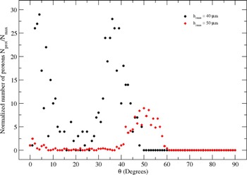
The highest energy protons for the 40 µm height cone with straight walls are accelerated at low divergence angles between 2° and 4° same as at 30°–40°, as can be seen in Figure 11. At the same time the highest energy protons for the 50 µm height cone with straight walls are accelerated only at high divergence angle 50° ≤ θ ≤ 55°.

Fig. 11. Normalized number of protons N prot/N forward as a function of proton divergence angle θ for a cone target with straight walls. The cone heights are 40 and 50 µm, and the angle α = 10°.
The cone target with straight walls and the height of 40 µm accelerates protons better than the cone target with straight walls and the height of 50 µm, and for an angle α of 10°.
4. CONCLUSIONS
We studied two kinds of cones with curved and straight walls as targets, which interact with a ultra-high intensity laser pulse. We investigated for a flat-top cone target with curved walls and a height of 40 µm the influence of the angle between the cone symmetry axis and the laser propagation direction, α on the proton acceleration. We have obtained that the best angle α to get a collimated high-energy proton beam of protons is 10° thanks to a better compromise between laser absorption in high-energy electrons and maximum accelerating electrostatic field at the back of the flat-top. The protons are better accelerated for a flat-top cone target with curved walls and a height of 40 µm than for a flat-top cone target with curved walls and a height of 50 µm at the same value of 10° for the angle α. We note, also, that the flat-top cone target with curved walls can accelerate protons to higher energies, with higher laser absorption and in a higher number than the cone target with straight walls and the same height and value of the incidence angle α. This study will allow one to optimize laser-ion acceleration on the CETAL facility and to progress toward applications in view of future experiments at ELI-NP.
ACKNOWLEDGMENTS
This work has been financed by the National Authority for Research and Innovation in the frame of Nucleus program-contract 4N/2016 and by the national project PN III 5/5.1/ELI-RO, No. 04-ELI/2016 (‘QLASNUC’), under the financial support of Institute for Atomic Physics – IFA.