


NOMENCLATURE
- a
-
length of the compliant structure
- b
-
height of the compliant structure
- C
-
specific fuel consumption
- E
-
Young's modulus
-
 $\overline {EA} $
-
equivalent extension stiffness
-
$\overline {EI} $
-
equivalent bending stiffness
- ES
-
entire length of the wing span extention
- F
-
actuation force
- I
-
second moment of area
- K
-
stiffness matrix of the equivalent beam
- Kc
-
coupling coefficient between the extention force and vertical deflection
- Kij
-
sub-blocks of the stiffness matrix of the equivalent beam (i, j = 1, 2)
- Ksy
-
coefficient between the vertical force and the vertical deflection
- Kt
-
combination of the axial and bending stiffness of the equivalent beams
- L
-
geometry parameter of the round corrugation: length
- L/D
-
Lift-to-Drag ratio
- Ln
-
length of the entire corrugated panel
- M
-
moment about z direction
- n
-
number of corrugations
- N
-
number of compliant structures
- P
-
aerodynamic force
- range
-
range of the aircraft
- rs
-
stiffness asymmetry
- R
-
geometry parameter of the round corrugation: radius
- S
-
wing span
- t
-
thickness of the corrugated panel
- u
-
nodal displacement in x direction
- v
-
nodal displacement in y direction
- vF
-
vertical deflection caused by the actuation force
- vP
-
vertical deflection caused by the aerodynamic force
- V
-
flight velocity
- w
-
width of the compliant structure
- Wf
-
final weight of the aircraft
- Wi
-
initial weight of the aircraft
- X
-
force in x direction
- Y
-
force in y direction
- α
-
rotation angle about z direction
- σv
-
Von Mises stress
- σy
-
yield stress
- FishBAC
-
fish bone active camber
- GNAT
-
gear driveN autonomous twin
Symbols


Abbreviations
1.0 INTRODUCTION
Research on morphing aircraft has aroused much attention in recent years. By changing the geometry actively during flight, morphing aircraft have the potential to conduct more flight missions with better performance compared to conventional aircraft, which are designed for fixed flight conditions. The research on morphing aircraft wings involves many interdisciplinary fields, such as novel morphing concepts(Reference Barbarino, Bilgen, Ajaj, Friswell and Inman1), novel actuators and sensors(Reference Sun, Guan, Liu and Leng2), and the conceptual-level analysis of morphing aircraft(Reference Crossley, Skillen, Frommer and Roth3). To develop morphing aircraft, one aspect that has to be investigated is the structural design.
One of the difficulties remaining in the structural design of morphing aircraft is the sensitive balance between the flexibility to change shape and the stiffness to carry the aerodynamic loads. According to Thill et al(Reference Thill, Etches, Bond, Potter and Weaver4), two basic approaches can be used to solve the dilemma, i.e. stiffness tailoring and actively controlled stiffness. One representative application of stiffness tailoring is the Fish Bone Active Camber (FishBAC) concept. The FishBAC is built using a highly anisotropic compliant structure, which has a very low chordwise bending stiffness but a high spanwise bending stiffness(Reference Woods, Bilgen and Friswell5,Reference Woods and Friswell6) . A fluid-structure interaction analysis was performed since the deflections of the morphing structures are large(Reference Woods, Dayyani and Friswell7). The capability of achieving variable stiffness usually relies on novel smart materials, such as shape memory polymers(Reference Chen, Chen, Zhang, Liu and Leng8), or a change of fluid pressure such as the flexible matrix composite actuator(Reference Shan, Philen, Bakis, Wang and Rahn9).
Although the performance of novel materials has improved significantly in recent years, some limitations still remain compared to conventional materials, e.g. the high cost, low reliability and sensitivity to the environment. Therefore, morphing aircraft may still require careful stiffness tailoring and conventional actuators to achieve shape change. For example, changing the span or dihedral angle is difficult since the spar is the primary structural member of the wing and the stiffness anisotropy cannot be easily integrated; in contrast for camber morphing, the load and deformation occurs in orthogonal directions allowing relatively easy stiffness tailoring. Some solutions have been proposed for spanwise morphing, e.g. the zigzag wing box concept(Reference Ajaj, Saavedra Flores, Friswell, Allegri, Woods, Isikveren and Dettmer10) and the Gear driveN Autonomous Twin (GNAT) spar(Reference Ajaj, Bourchak and Friswell11), which makes use of pinion and rack actuation systems. Due to the loads on the spar, the aero-structure analysis is important and a relatively heavy mechanism may be required to change the spanwise shape, which will reduce the performance of the morphing aircraft and limit the morphing concepts to small- and medium-sized unmanned air vehicles.
The winglet can be a suitable alternative to achieve spanwise morphing since the aerodynamic loads on the wing tip are relatively small. Aerodynamic analysis and optimisation has shown the potential benefits(Reference Smith, Ajaj, Isikveren and Friswell12,Reference Smith, Lowenberg, Jones and Friswell13) . Some structural solutions were also proposed, e.g. using conventional hinges and servo motors(Reference Falcão, Gomes and Suleman14). Compliant structures were investigated since the compliance allows for the shape change of morphing aircraft. For instance, corrugated structures have been used as the morphing skin to provide a continuous surface for a conventional hinge and servo motor system(Reference Ursache, Melin, Isikveren and Friswell15).
Despite the advantage of being flexible, the compliant structure can be tailored to have a relatively high capability of carrying aerodynamic loads. A novel compliant structure based on stiffness asymmetry has been introduced by the authors(Reference Wang, Khodaparast and Friswell16). A rotation angle of the compliant structure can be introduced by a linear actuation when the compliant structure has unsymmetrical stiffness in its different components. Increasing the stiffness asymmetry causes a larger deformation, whereas increasing the total stiffness will enable larger aerodynamic loads to be carried.
In this paper, the stiffness asymmetry is provided by round corrugated panels, which are made of isotropic material but have different geometries. At first, an equivalent model is developed for the round corrugated panel. The round corrugated panel is modelled as an equivalent beam, and the stiffness matrix of this equivalent beam is obtained by calculating deflections under external loads. Due to the fixed boundary condition, coupling terms between the axial force and vertical deflection and rotation angle are found analytically. Although the coupling effect can be eliminated, including the coupling terms makes the method more general but does require optimisation. Then, the equivalent model is validated by detailed finite element models in the commercial software Abaqus® and by experimental tests. The results show good agreement. Finally, optimisation cases are demonstrated on the single compliant structure as well as the compliant structure consisting of multiple units, including a case study under fixed span and aerodynamic loads and a case study of an aircraft with fewer constraints, which shows improved performance compared to a fixed geometry.
2.0 CONCEPT OF COMPLIANT STRUCTURES BASED ON STIFFNESS ASYMMETRY
Figure 1 shows an example of the proposed compliant structure. The compliant structure consists of two corrugated panels with different stiffnesses, which are fixed at one end and connected by a relatively rigid part at the other end. A linear actuator is installed to deform the compliant structure.
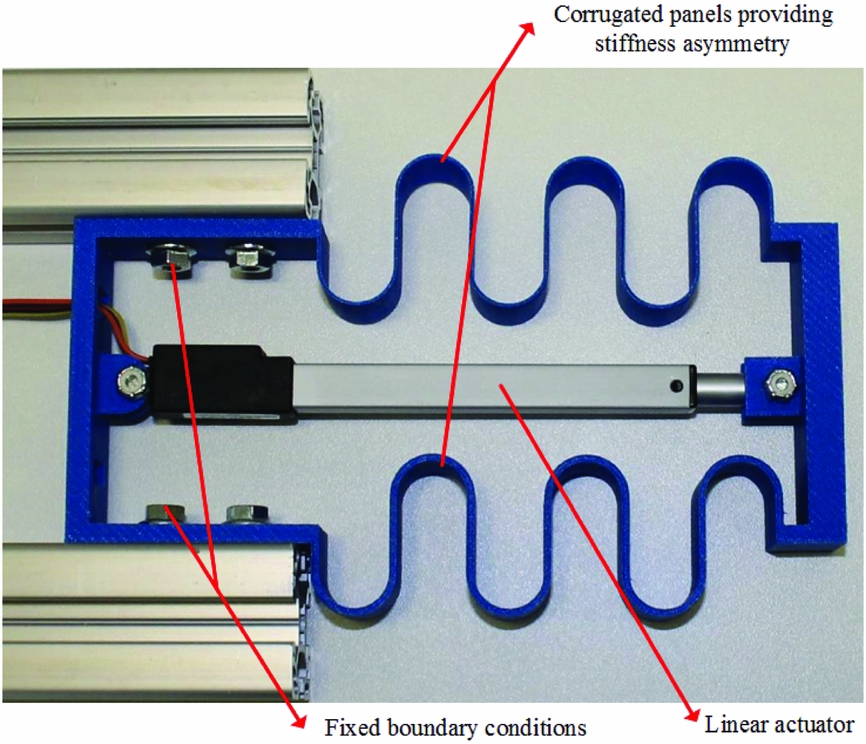
Figure 1. A compliant structure based on stiffness asymmetry.
The authors have derived the closed-form equations that give the relationship between the vertical deflections of the compliant structure, vF and vP , due to the actuation force, F, and aerodynamic force, P as(Reference Wang, Khodaparast and Friswell16):
 $$\begin{equation}
\begin{array}{@{}l@{}} {v_F} = \displaystyle\frac{{Fb{a^2}}}{2}\frac{{{{\overline {EA} }_2} - {{\overline {EA} }_1}}}{{2{K_t}}} = \frac{{Fb{a^2}}}{{4{K_t}{{\overline {EA} }_1}}}\left( {{r_s} - 1} \right)\\[10pt] {v_P} = \displaystyle\frac{{\left( {3{{\overline {EA} }_1}{{\overline {EA} }_2}{b^2}/{K_t} - 4} \right)}}{{12({{\overline {EI} }_1} + {{\overline {EI} }_2})}}P{a^3} \end{array},
\end{equation}$$
$$\begin{equation}
\begin{array}{@{}l@{}} {v_F} = \displaystyle\frac{{Fb{a^2}}}{2}\frac{{{{\overline {EA} }_2} - {{\overline {EA} }_1}}}{{2{K_t}}} = \frac{{Fb{a^2}}}{{4{K_t}{{\overline {EA} }_1}}}\left( {{r_s} - 1} \right)\\[10pt] {v_P} = \displaystyle\frac{{\left( {3{{\overline {EA} }_1}{{\overline {EA} }_2}{b^2}/{K_t} - 4} \right)}}{{12({{\overline {EI} }_1} + {{\overline {EI} }_2})}}P{a^3} \end{array},
\end{equation}$$
where
 $\overline {EA} $
is the equivalent extension stiffness,
$\overline {EA} $
is the equivalent extension stiffness,
 $\overline {EI} $
is the equivalent bending stiffness, the subscript ‘1’ and ‘2’ correspond to the different beams, respectively. The length, height and width of the compliant structure are represented as a, b and w. The term Kt
represents the combination of the axial and bending stiffness of the equivalent beams, and the ratio rs
represents the stiffness asymmetry as:
$\overline {EI} $
is the equivalent bending stiffness, the subscript ‘1’ and ‘2’ correspond to the different beams, respectively. The length, height and width of the compliant structure are represented as a, b and w. The term Kt
represents the combination of the axial and bending stiffness of the equivalent beams, and the ratio rs
represents the stiffness asymmetry as:
 $$\begin{equation}
\begin{array}{@{}l@{}} {K_t} = \ {\overline {EA} _1}{\overline {EI} _1} + {\overline {EA} _2}{\overline {EI} _2} + {\overline {EA} _1}{\overline {EI} _2} + {\overline {EI} _1}{\overline {EA} _2} + {\overline {EA} _1}{\overline {EA} _2}{b^2}\\[5pt] {r_s} = \displaystyle\frac{{{{\overline {EA} }_2}}}{{{{\overline {EA} }_1}}} \end{array}
\end{equation}$$
$$\begin{equation}
\begin{array}{@{}l@{}} {K_t} = \ {\overline {EA} _1}{\overline {EI} _1} + {\overline {EA} _2}{\overline {EI} _2} + {\overline {EA} _1}{\overline {EI} _2} + {\overline {EI} _1}{\overline {EA} _2} + {\overline {EA} _1}{\overline {EA} _2}{b^2}\\[5pt] {r_s} = \displaystyle\frac{{{{\overline {EA} }_2}}}{{{{\overline {EA} }_1}}} \end{array}
\end{equation}$$
According to Equation (1), a vertical deflection can be induced if the equivalent extension stiffnesses of the two corrugated panels are different, while the vertical deflection caused by the aerodynamic force can be reduced by increasing the total stiffness. This relationship provides the possibilities to reduce the actuation force while carrying the aerodynamic force simultaneously if an optimisation can be performed, but the requirements to explore the design space also motivates the application of the equivalent model.
3.0 EQUIVALENT STIFFNESS MATRIX OF A ROUND CORRUGATED PANEL
The compliant structure can be represented by the equivalent model as shown in Fig. 2(a), which consists of the equivalent elements representing the corrugated panels and the normal beam elements representing the connection part in the two-dimensional situation.
Figure 2. (a) Equivalent model of the compliant structure; (b) Equivalent beam element representing the corrugated panel.
In this paper, corrugated panels, which have fixed boundary conditions, are represented by the equivalent beam elements shown in Fig. 2(b). The stiffness asymmetry will be provided by using different geometry parameters in the two panels.
The equivalent beam has two nodes, i.e. i and j. The nodal loads are represented by X (force in x direction), Y (force in y direction), M (moment about z direction). The nodal displacements are represented as u (displacement in x direction), v (displacement in y direction) and α (rotation angle about z direction), respectively. The relationship between the nodal loads and the displacements can be expressed as
 $$\begin{equation}
\left[ {\begin{array}{@{}*{1}{c}@{}} {{X_i}}\\ {{Y_i}}\\ {{M_i}}\\ {{X_j}}\\ {{Y_j}}\\ {{M_j}} \end{array}} \right] = \left[ {\begin{array}{@{}*{6}{c}@{}} {{k_{11}}}&{{k_{12}}}&{{k_{13}}}&{{k_{14}}}&{{k_{15}}}&{{k_{16}}}\\ {}&{{k_{22}}}&{{k_{23}}}&{{k_{24}}}&{{k_{25}}}&{{k_{26}}}\\ {}&{}&{{k_{33}}}&{{k_{34}}}&{{k_{35}}}&{{k_{36}}}\\ {}&{}&{}&{{k_{44}}}&{{k_{45}}}&{{k_{46}}}\\ {}&{}&{}&{}&{{k_{55}}}&{{k_{56}}}\\ {sym.}&{}&{}&{}&{}&{{k_{66}}} \end{array}} \right]\left[ {\begin{array}{@{}*{1}{c}@{}} {{u_i}}\\ {{v_i}}\\ {{\alpha _i}}\\ {{u_j}}\\ {{v_j}}\\ {{\alpha _j}} \end{array}} \right] = K\left[ {\begin{array}{@{}*{1}{c}@{}} {{u_i}}\\ {{v_i}}\\ {{\alpha _i}}\\ {{u_j}}\\ {{v_j}}\\ {{\alpha _j}} \end{array}} \right],
\end{equation}$$
$$\begin{equation}
\left[ {\begin{array}{@{}*{1}{c}@{}} {{X_i}}\\ {{Y_i}}\\ {{M_i}}\\ {{X_j}}\\ {{Y_j}}\\ {{M_j}} \end{array}} \right] = \left[ {\begin{array}{@{}*{6}{c}@{}} {{k_{11}}}&{{k_{12}}}&{{k_{13}}}&{{k_{14}}}&{{k_{15}}}&{{k_{16}}}\\ {}&{{k_{22}}}&{{k_{23}}}&{{k_{24}}}&{{k_{25}}}&{{k_{26}}}\\ {}&{}&{{k_{33}}}&{{k_{34}}}&{{k_{35}}}&{{k_{36}}}\\ {}&{}&{}&{{k_{44}}}&{{k_{45}}}&{{k_{46}}}\\ {}&{}&{}&{}&{{k_{55}}}&{{k_{56}}}\\ {sym.}&{}&{}&{}&{}&{{k_{66}}} \end{array}} \right]\left[ {\begin{array}{@{}*{1}{c}@{}} {{u_i}}\\ {{v_i}}\\ {{\alpha _i}}\\ {{u_j}}\\ {{v_j}}\\ {{\alpha _j}} \end{array}} \right] = K\left[ {\begin{array}{@{}*{1}{c}@{}} {{u_i}}\\ {{v_i}}\\ {{\alpha _i}}\\ {{u_j}}\\ {{v_j}}\\ {{\alpha _j}} \end{array}} \right],
\end{equation}$$
where the stiffness matrix of the equivalent beam is denoted by K.
The stiffness matrix of the round corrugated panel is obtained by calculating the deflection under different load cases. The internal load of a corrugated panel is shown in Fig. 3. The geometry variables of the round corrugation are the length of straight part L and the radius R, and the Young's modulus and second moment of area are E and I, respectively. The deflection of a single corrugated panel unit can be calculated by combining the deflections of the separate beams in the corrugated panel, which can be obtained using simple classical mechanics.

Figure 3. Internal load of the round corrugated panel under the axial force X and vertical force Y.
The deformation of the corrugated panel, that has multiple corrugations, can be calculated by combining the deflections of each corrugation. The deflections can then be expressed as
 $$\begin{equation}
\begin{array}{@{}l@{}} u_n^X = \displaystyle\frac{{X{L_n}}}{{\overline {EA} }}\\[8pt] v_n^X = \displaystyle\frac{X}{{{K_{yx}}}}\\[8pt] \displaystyle\alpha _n^X = 0 \end{array},
\end{equation}$$
$$\begin{equation}
\begin{array}{@{}l@{}} u_n^X = \displaystyle\frac{{X{L_n}}}{{\overline {EA} }}\\[8pt] v_n^X = \displaystyle\frac{X}{{{K_{yx}}}}\\[8pt] \displaystyle\alpha _n^X = 0 \end{array},
\end{equation}$$
 $$\begin{equation}
\begin{array}{@{}l@{}} \displaystyle u_n^Y = \frac{Y}{{{K_{xy}}}}\\[8pt]
\displaystyle v_n^Y = \frac{{Y{L_n}^3}}{{3\overline {EI} }} + \frac{Y}{{{K_{sy}}}}\\[8pt]
\displaystyle\alpha _n^Y = \frac{{Y{L_n}^2}}{{2\overline {EI} }} \end{array},
\end{equation}$$
$$\begin{equation}
\begin{array}{@{}l@{}} \displaystyle u_n^Y = \frac{Y}{{{K_{xy}}}}\\[8pt]
\displaystyle v_n^Y = \frac{{Y{L_n}^3}}{{3\overline {EI} }} + \frac{Y}{{{K_{sy}}}}\\[8pt]
\displaystyle\alpha _n^Y = \frac{{Y{L_n}^2}}{{2\overline {EI} }} \end{array},
\end{equation}$$
 $$\begin{equation}
\begin{array}{@{}l@{}} \displaystyle u_n^M = 0\\[4pt] \displaystyle v_n^M = \frac{{M{L_n}^2}}{{2\overline {EI} }}\\[10pt] \displaystyle\alpha _n^M = \frac{{M{L_n}}}{{\overline {EI} }} \end{array},
\end{equation}$$
$$\begin{equation}
\begin{array}{@{}l@{}} \displaystyle u_n^M = 0\\[4pt] \displaystyle v_n^M = \frac{{M{L_n}^2}}{{2\overline {EI} }}\\[10pt] \displaystyle\alpha _n^M = \frac{{M{L_n}}}{{\overline {EI} }} \end{array},
\end{equation}$$
where
 $$\begin{equation}
\begin{array}{@{}l@{}} {L_n} = n \cdot 4R\\[3pt] \overline {EA} = \displaystyle\frac{{12R \cdot EI}}{{4{L^3} + 6\pi R{L^2} + 24{R^2}L + 3\pi {R^3}}}\\[10pt] \overline {EI} = \displaystyle\frac{{2R \cdot EI}}{{\pi R + 2L}}\\[8pt] {K_{yx}} = {K_{xy}} = {K_c} = \displaystyle\frac{1}{2}\frac{{EI}}{{nR\left( {{L^2} + \pi RL + 2{R^2}} \right)}}\\[3pt] {K_{sy}} = \displaystyle\frac{{3EI}}{{{R^2}n\left( {\pi R + 8L} \right)}} \end{array}
\end{equation}$$
$$\begin{equation}
\begin{array}{@{}l@{}} {L_n} = n \cdot 4R\\[3pt] \overline {EA} = \displaystyle\frac{{12R \cdot EI}}{{4{L^3} + 6\pi R{L^2} + 24{R^2}L + 3\pi {R^3}}}\\[10pt] \overline {EI} = \displaystyle\frac{{2R \cdot EI}}{{\pi R + 2L}}\\[8pt] {K_{yx}} = {K_{xy}} = {K_c} = \displaystyle\frac{1}{2}\frac{{EI}}{{nR\left( {{L^2} + \pi RL + 2{R^2}} \right)}}\\[3pt] {K_{sy}} = \displaystyle\frac{{3EI}}{{{R^2}n\left( {\pi R + 8L} \right)}} \end{array}
\end{equation}$$
The subscript n denotes the number of corrugations and the superscripts X, Y and M represent the external loads causing the displacement. The length of the entire corrugated panel is represented by Ln . The coupling coefficient between the extension force and the vertical deflection is denoted as Kc and the coefficient between the vertical force and vertical deflection as Ksy .
As shown in the Equations (4)-(7), the force in the x direction will lead to a displacement in the y direction, and vice-versa. The coupling effect will cause an additional vertical deflection of the proposed compliant structure, which makes the analytical expression shown in Equation (1) insufficient to obtain the final vertical deflection of the proposed compliant structure. The coupling effect was first investigated in an earlier study(Reference Wang, Khodaparast, Friswell and Shaw17), in which the vertical deflection caused by the force X is explained. The detailed method to calculate the displacements and rotation angle caused by the axial force has also been explained in(Reference Wang, Khodaparast, Friswell and Shaw17). In the current paper, the coupling relationships including the axial displacement caused by the force Y is obtained in Equation (5). The complete relationship between the nodal deflections and loads makes the stiffness matrix of the corrugated panel available, which provides a more general and compatible approach to calculate the deformation of the entire compliant structure.
The stiffness matrix of the equivalent beam is obtained by calculating the nodal deflections when the equivalent beam has a fixed boundary condition at one node (i or j) and the external load is applied at the other node (j or i). For example, the deflections of node j are calculated under the load [0, 0, 0, Xj , Yj , Mj ] when node i is constrained. According to Equations (4)-(7) we have
 $$\begin{equation}
\left[ {\begin{array}{@{}*{1}{c}@{}} {{u_j}}\\ {{v_j}}\\ {{\alpha _j}} \end{array}} \right] = \left[ {\begin{array}{@{}*{3}{c}@{}} {\displaystyle\frac{{{L_n}}}{{\overline {EA} }}}&{\displaystyle\frac{1}{{{K_c}}}}&0\\[8pt] {\displaystyle\frac{1}{{{K_c}}}}&{\displaystyle\frac{{L_n^3}}{{3\overline {EI} }} + \displaystyle\frac{1}{{{K_{sy}}}}}&{\displaystyle\frac{{L_n^2}}{{2\overline {EI} }}}\\[8pt] 0&{\displaystyle\frac{{L_n^2}}{{2\overline {EI} }}}&{\displaystyle\frac{{{L_n}}}{{\overline {EI} }}} \end{array}} \right]\left[ {\begin{array}{@{}*{1}{c}@{}} {{X_j}}\\ {{Y_j}}\\ {{M_j}} \end{array}} \right]
\end{equation}$$
$$\begin{equation}
\left[ {\begin{array}{@{}*{1}{c}@{}} {{u_j}}\\ {{v_j}}\\ {{\alpha _j}} \end{array}} \right] = \left[ {\begin{array}{@{}*{3}{c}@{}} {\displaystyle\frac{{{L_n}}}{{\overline {EA} }}}&{\displaystyle\frac{1}{{{K_c}}}}&0\\[8pt] {\displaystyle\frac{1}{{{K_c}}}}&{\displaystyle\frac{{L_n^3}}{{3\overline {EI} }} + \displaystyle\frac{1}{{{K_{sy}}}}}&{\displaystyle\frac{{L_n^2}}{{2\overline {EI} }}}\\[8pt] 0&{\displaystyle\frac{{L_n^2}}{{2\overline {EI} }}}&{\displaystyle\frac{{{L_n}}}{{\overline {EI} }}} \end{array}} \right]\left[ {\begin{array}{@{}*{1}{c}@{}} {{X_j}}\\ {{Y_j}}\\ {{M_j}} \end{array}} \right]
\end{equation}$$
The loads can be obtained from Equation (8), by inverting the compliance matrix as
 $$\begin{equation}
\left[ {\begin{array}{@{}*{1}{c}@{}} {{X_j}}\\ {{Y_j}}\\ {{M_j}} \end{array}} \right] = \left[ {{K_{22}}} \right]\left[ {\begin{array}{@{}*{1}{c}@{}} {{u_j}}\\ {{v_j}}\\ {{\alpha _j}} \end{array}} \right]
\end{equation}$$
$$\begin{equation}
\left[ {\begin{array}{@{}*{1}{c}@{}} {{X_j}}\\ {{Y_j}}\\ {{M_j}} \end{array}} \right] = \left[ {{K_{22}}} \right]\left[ {\begin{array}{@{}*{1}{c}@{}} {{u_j}}\\ {{v_j}}\\ {{\alpha _j}} \end{array}} \right]
\end{equation}$$
Using the equilibrium equations, we can obtain the loads at node i as
 $$\begin{equation}
\left[ {\begin{array}{@{}*{1}{c}@{}} {{X_i}}\\ {{Y_i}}\\ {{M_i}} \end{array}} \right] = \left[ {{K_{12}}} \right]\left[ {\begin{array}{@{}*{1}{c}@{}} {{u_j}}\\ {{v_j}}\\ {{\alpha _j}} \end{array}} \right]
\end{equation}$$
$$\begin{equation}
\left[ {\begin{array}{@{}*{1}{c}@{}} {{X_i}}\\ {{Y_i}}\\ {{M_i}} \end{array}} \right] = \left[ {{K_{12}}} \right]\left[ {\begin{array}{@{}*{1}{c}@{}} {{u_j}}\\ {{v_j}}\\ {{\alpha _j}} \end{array}} \right]
\end{equation}$$
Repeating the previous step, we can find the relationship of the node loads and deflections when the beam is under the load [Xi , Yi , Mi , 0, 0, 0]. The complete relationship between the loads [Xi , Yi , Mi , Xj , Yj , Mj ] and the deflections [ui , vi , αi , uj , vj , αj ] can be obtained according to the principle of superposition as
 $$\begin{equation}
\left[ {\begin{array}{@{}*{1}{c}@{}} {{X_i}}\\ {{Y_i}}\\ {{M_i}}\\ {{X_j}}\\ {{Y_j}}\\ {{M_j}} \end{array}} \right] = \left[ {\begin{array}{@{}*{2}{c}@{}} {{K_{11}}}&{{K_{12}}}\\ {{K_{21}}}&{{K_{22}}} \end{array}} \right]\left[ {\begin{array}{@{}*{1}{c}@{}} {{u_i}}\\ {{v_i}}\\ {{\alpha _i}}\\ {{u_j}}\\ {{v_j}}\\ {{\alpha _j}} \end{array}} \right]
\end{equation}$$
$$\begin{equation}
\left[ {\begin{array}{@{}*{1}{c}@{}} {{X_i}}\\ {{Y_i}}\\ {{M_i}}\\ {{X_j}}\\ {{Y_j}}\\ {{M_j}} \end{array}} \right] = \left[ {\begin{array}{@{}*{2}{c}@{}} {{K_{11}}}&{{K_{12}}}\\ {{K_{21}}}&{{K_{22}}} \end{array}} \right]\left[ {\begin{array}{@{}*{1}{c}@{}} {{u_i}}\\ {{v_i}}\\ {{\alpha _i}}\\ {{u_j}}\\ {{v_j}}\\ {{\alpha _j}} \end{array}} \right]
\end{equation}$$
Here, the stiffness matrix K is represented by four blocks K 11, K 12, K 21 and K 22. It should also be noted that the stiffness matrix is obtained when the round corrugated panel is clamped at point A as shown in Fig. 3. If the round corrugated panel is clamped at point A’, the displacement under extension force will be in the opposite direction, changing the stiffness matrix form of the equivalent beam. In contrast to the normal beam element, the equivalent stiffness matrix has coupling components between the extension force X and the displacement in the y direction, v, the rotation angle, α, due to the coupling effect.
The stiffness matrix of the proposed compliant structure is then built up by assembling the stiffness matrix of each element in the structure. As shown in Fig. 2(a), one compliant structure is made of four elements and five nodes. Two equivalent beam elements are used to represent the two round corrugated panels and two normal beam elements for the middle part. The actuation force F is applied at node 3 and aerodynamic force P at node 2 to simulate the external loads. Both node 1 and node 5 are fixed to simulate the boundary conditions.
4.0 VERIFICATION OF THE EQUIVALENT MODEL
4.1 Finite element analysis
To verify the equivalent stiffness matrix, parametric studies are conducted and the results are compared to those obtained from detailed finite element analysis. Two calculation cases are used for the verification.
The finite element analysis is conducted in the commercial software Abaqus®. S4R shell elements are used in the detailed models since the S4R element has a good accuracy for both thin and thick plates(Reference Simulia18). The mesh size is 0.001 m. Since the length, height and width of the compliant structure is 0.12 m, 0.1 m and 0.01 m, respectively, for case 1, and 0.16 m, 0.2 m and 0.01 m, respectively, for case 2, the mesh size is sufficiently small to ensure convergence. Figure 4(a) shows the mesh of the Abaqus model and Fig. 4(b) shows the vertical deflections obtained.
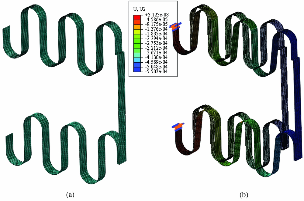
Figure 4. (a) Mesh of the finite element model, (b) An example of the vertical deflections obtained.
The geometry variables of the two corrugated panels are represented by L 1, R 1 and L 2, R 2. The thicknesses are denoted by t 1 and t 2, respectively. The numbers of the corrugation units of the two corrugated panels are denoted by n 1 and n 2, respectively. The stiffness asymmetry is achieved by changing the thickness of one panel (t 2). The material's Young's modulus and the Poisson's ratio of the material are 72 GPa and 0.3, respectively. Both the actuation force and the aerodynamic force are taken into account for the two cases. The actuation force is applied in the middle of the outboard beam, so that node 3 is equidistant from nodes 2 and 4.
The vertical deflection of node 3 is obtained for the comparison. The error between the stiffness matrix method and the detailed Abaqus analysis is below 3%. But the efficiency of the analysis is improved significantly by using the equivalent beam model of the corrugated panel. For example, the CPU time of each computation is 7.3 seconds for the detailed Abaqus analysis in Fig. 5, while the CPU time is only 0.2 seconds for the equivalent model written in Matlab. The computation is performed with a Xeon E3 work station with 32-GB memory.
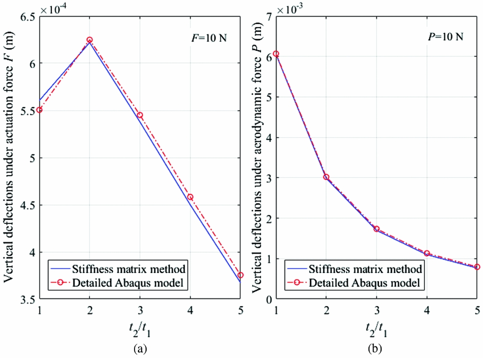
Figure 5. Verification of the compliant structure equivalent model by detailed finite element analysis: case 1 (a = 0.12 m, b = 0.1 m, w = 0.01 m, R 1 = 0.01 m, L 1 = 0.015 m, R 2 = 0.01 m, L 2 = 0.015 m, t 1 = 0.002 m, n 1 = 3, n 2 = 3).
In Fig. 5, the vertical deflection under the actuation force increases first before it drops. The increase is due to the stiffness asymmetry caused by the different panel thickness. The coupling effect between the extension force and the vertical deflection is shown by the vertical deflection when the ratio of t 2 /t 1 is 1, since the extension stiffnesses of the two corrugated panels are the same at this point. The vertical deflection caused by the coupling can be even larger than that caused by the stiffness asymmetry as shown in Fig. 6, where the vertical deflection under actuation force is reduced continuously even if the stiffness asymmetry is increased. The vertical deflection under aerodynamic force always decreases due to the increase of the total stiffness.
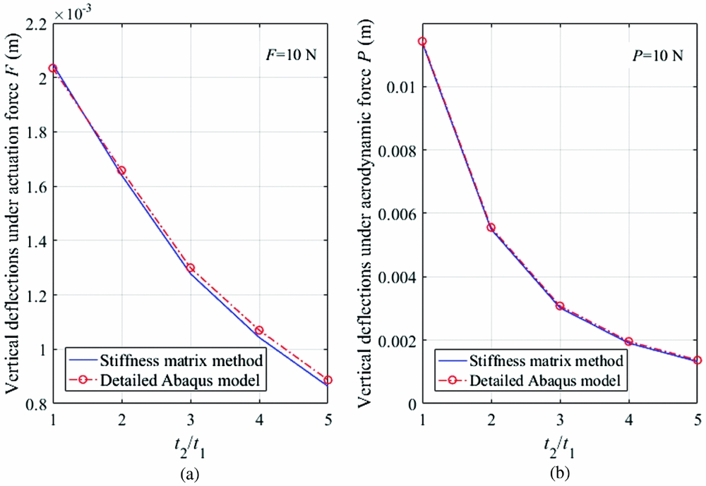
Figure 6. Verification of the compliant structure equivalent model by detailed finite element analysis: case 2 (a = 0.16 m, b = 0.2 m, w = 0.01 m, R 1 = 0.02 m, L 1 = 0.02 m, R 2 = 0.02 m, L 2 = 0.02 m, t 1 = 0.002 m, n 1 = 2, n 2 = 2).
4.2 Experimental test
Samples of the compliant structures are manufactured by 3D printing. As shown in Fig. 7(a), one corrugated panel is clamped by two screws to ensure the fixed boundary condition and the compliant structure is actuated by a linear actuator. A controller is used to control the feedback position of the actuator, and the power for the actuator is provided by batteries. The connections between the linear actuator and the structure are pinned to ensure that the linear actuation force can be provided and the rotation of the compliant structure cannot\break be influenced. The movement of the sample is recorded by a camera perpendicular to it. Three samples are manufactured with their geometry parameters as summarised in Table 1. Sample 1 and Sample 2 have the same geometry parameters. In Sample 1, the two round corrugated panels are both clamped at point A, while in Sample 2, one round corrugated panel is clamped at point A, and the other at point A’, which leads to the opposite corrugated direction as shown by the red arrows in Fig. 7(a). Sample 3 has the same corrugated directions for both corrugated panels, but the thicknesses of the panels are not the same, which will cause a stiffness asymmetry in the compliant structure.
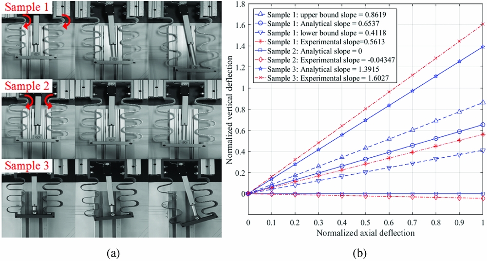
Figure 7. (a): Deflections of the sample under actuation; (b) Comparison of the slopes between the lateral and axial deflections.
Table 1 Geometry parameters of the samples
The deflections of the samples are measured from the digital photographs. Figure 7(a) shows the different deformations of the samples and Fig. 7(b) shows the comparison of the deflections between the analytical and experimental results. The deflections are normalised to show the different slopes since the rotation of the compliant structure is one of its key features, and the slope of the curve is determined by the geometry properties, not related to the material properties and actuation force. Sample 2 has almost no vertical deflection since its two corrugated panels have opposite vertical deflections, cancelling out the final rotation of the whole compliant structure. Since the two corrugated panels of Sample 1 have the same stiffness, the vertical deflection is only caused by the coupling effect. However, in Sample 3, a larger slope is found due to the stiffness asymmetry in the compliant structure. Although some errors exist between the analytical and experimental results, the differences are reasonable due to manufacturing tolerance.
The resolution of the 3D printer is 0.1 mm(19), which means the error in the geometry parameters could be 0.1 mm in the samples. For instance, the influence of the geometry uncertainty in Sample 1 due to manufacturing is shown in Fig. 7(b). The geometry uncertainty is included in the equivalent model to obtain the upper and lower bounds of the slope of Sample 1, in which the geometry variables are within the range as follows:
 $$\begin{equation}
\left\{ {\begin{array}{@{}*{1}{c}@{}} {{L_j} - 1\% \cdot {L_j} \le {L_j} \le {L_j} + 1\% \cdot {L_j}}\\ {{R_j} - 1\% \cdot {R_j} \le {R_j} \le {R_j} + 1\% \cdot {R_j}}\\ {{t_j} - 5\% \cdot {t_j} \le {t_j} \le {t_j} + 5\% \cdot {t_j}} \end{array}} \right.
\end{equation}$$
$$\begin{equation}
\left\{ {\begin{array}{@{}*{1}{c}@{}} {{L_j} - 1\% \cdot {L_j} \le {L_j} \le {L_j} + 1\% \cdot {L_j}}\\ {{R_j} - 1\% \cdot {R_j} \le {R_j} \le {R_j} + 1\% \cdot {R_j}}\\ {{t_j} - 5\% \cdot {t_j} \le {t_j} \le {t_j} + 5\% \cdot {t_j}} \end{array}} \right.
\end{equation}$$
Here, in Sample 1, Lj = 0.01 m, Rj = 0.01 m and tj = 0.002 m (j =1, 2).
The error between the experimental and analytical slopes of Sample 1 is within the range determined by the manufacturing process, which verifies the analytical result.
5.0 OPTIMISATION OF THE COMPLIANT STRUCTURE
5.1 Optimisation of a single compliant structure unit
To achieve a larger deformation, multiple units of the compliant structure can be used together. As shown in Fig. 8, the superscript i means the unit number. Each compliant structure is under the actuation force Fi and aerodynamic force Pi . Since the compliant structure is installed in the wing structure, the height of the structure, b, is determined by the thickness of the aerofoil, which is assumed to be a fixed parameter in the optimisation.
Figure 8. (a) Forces on the multiple units of the compliant structure; (b) Variables and forces for a single compliant structure.
The optimisation is performed using the Matlab Global Optimization Toolbox(20) and a genetic algorithm. An optimisation case is first conducted for a single compliant structure, in which the length a, height b and width w are all fixed parameters. The genetic algorithm has 200 individuals and 600 generations in this case. The variables are the geometry parameters of the two round corrugated panels as shown in Fig. 8(b). The number of the corrugations, n 1,2, should be integers. The bounds of the variables are shown below for the case study:
 $$\begin{equation}
\left\{ {\begin{array}{@{}*{1}{l}@{}} {{t_{1,2}}\left( {0.001 \le {t_{1,2}} \le 0.02\;{\rm{m}}} \right)}\\ {{L_{1,2}}\left( {0.01 \le {L_{1,2}} \le 0.05\;{\rm{m}}} \right)}\\ {{n_{1,2}}\left( {1 \le {n_{1,2}} \le 4,n = 1,\;2...} \right)} \end{array}} \right.
\end{equation}$$
$$\begin{equation}
\left\{ {\begin{array}{@{}*{1}{l}@{}} {{t_{1,2}}\left( {0.001 \le {t_{1,2}} \le 0.02\;{\rm{m}}} \right)}\\ {{L_{1,2}}\left( {0.01 \le {L_{1,2}} \le 0.05\;{\rm{m}}} \right)}\\ {{n_{1,2}}\left( {1 \le {n_{1,2}} \le 4,n = 1,\;2...} \right)} \end{array}} \right.
\end{equation}$$
The objective is to minimise the actuation force Fi required to achieve a specified rotation angle of the structure. The influence of the axial deflection is taken into account when the rotation angle is calculated since the deflection could be relatively large compared to the length of the structure. Geometry constraints are applied to the compliant structure, to provide a realistic geometry and enough space to install the actuation system. Thus,
 $$\begin{equation}
\begin{array}{@{}l@{}} {L_1} + {R_1} + {L_2} + {R_2} < b/2\\ {t_j} < {L_j}/5\, (j = 1,2)\\ {t_j} < {R_j}/5\, (j = 1,2) \end{array},
\end{equation}$$
$$\begin{equation}
\begin{array}{@{}l@{}} {L_1} + {R_1} + {L_2} + {R_2} < b/2\\ {t_j} < {L_j}/5\, (j = 1,2)\\ {t_j} < {R_j}/5\, (j = 1,2) \end{array},
\end{equation}$$
where the round radius Rj is determined by the length of the structure a and the number of corrugations as Rj = a/(4nj ) (j = 1, 2).
A non-linear constraint is added to control the largest Von Mises stress in the corrugated panel as
 $$\begin{equation}
{\rm{max}}\;{\sigma _v} \le {\sigma _y},
\end{equation}$$
$$\begin{equation}
{\rm{max}}\;{\sigma _v} \le {\sigma _y},
\end{equation}$$
where σv and σy are the Von Mises stress and the yield stress of the material, respectively. The Von Mises stress in the corrugated panel is obtained by calculating the nodal loads in the equivalent beam element after the nodal displacements of the structure are obtained. The yield stress is 270 MPa, the material's Young's modulus is 72 GPa, and the Poisson's ratio is 0.3 in this study.
Figure 9(a) shows the optimum actuation force when the required rotation angle varies from 0 to 10° with different aerodynamic forces. A larger actuation force will be required if the required angle or the aerodynamic force is increased.
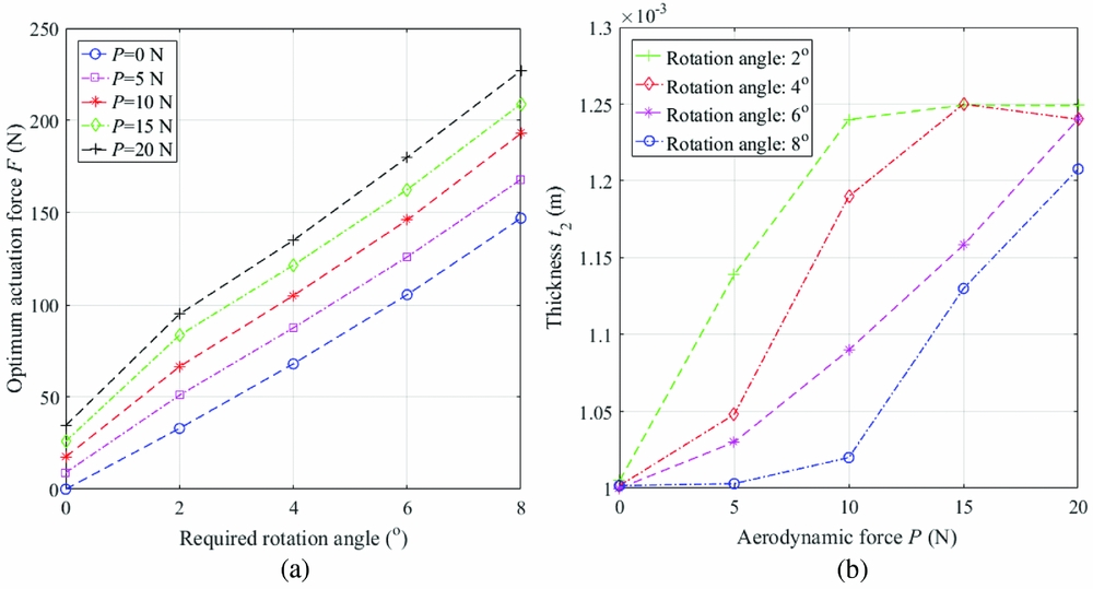
Figure 9. (a) Optimum actuation force vs required rotation angle, (b) Optimum thickness t 2 vs aerodynamic force.
When the required rotation angle is 0, which means the compliant structure is only supposed to maintain the geometry, the optimum variables are different than those when the compliant structure is supposed to deform (the required rotation angle is larger than 0). The optimum variables are summarised in Table 2. The different optimum variables to maintain geometry and to deform the structure indicate the influence of the deformation of the structure.
Table 2 Optimum variables of the compliant structure
Note that the optimum value t 2 varies, as shown in Fig. 9(b).
While the other variables are fixed, the trend of the panel thickness in the lower part t2 represents the change of total stiffness and stiffness asymmetry in the compliant structure. As shown in Fig. 9(b), the thickness t2 panel is influenced significantly by the required rotation angle and the aerodynamic force. According to Equation (7), the equivalent extension stiffness will be determined by the geometry parameter and the material's Young's modulus E. When the aerodynamic force increases, the thickness t 2 is increased to provide a relatively large total stiffness of the structure since the other parameters are fixed. The stiffness asymmetry of the structure is also increased, which can help to increase the rotation angle, or reduce the actuation force if the rotation angle is specified. Although the number of corrugations are at their upper bound, providing the smallest R and increasing the extension stiffnesses of the corrugated panels, the thickness t 1 is at its lowest bound, which provides the smallest extension stiffness to the corrugated panel. A compromise has been made by the optimum variables to satisfy the constraint and to determine an optimum stiffness allocation in the structure. With the trade-off design, the total stiffness can be large enough to carry the load P due to the smallest R, while large stiffness asymmetry can also be induced due to the different L and t in the two corrugated panels.
5.2 Optimisation of multiple units of compliant structures
Since the optimisation of one single compliant structure requires six variables, it is necessary to decompose the optimisation of the multiple units of compliant structures to sub-problems for each of the compliant structures.
As shown in Fig. 10(a), the multiple units of compliant structures are installed to extend the wing span of a baseline design. In this case, the length of each compliant structure is identical. Thus, the entire length of extension will be ES = N · a. The extended length ES is determined by the wing structure and flight conditions. It is obvious that a larger ES will cause a larger possible deformation, which could lead to more morphing benefits. But the extension of the wing span is constrained by the wing root bending moment and flutter performance of the aircraft due to the increase weight at the wing tip. Figure 10(b) shows a conceptual design of the compliant structure, illustrating the corrugated panels and actuators, as well as a solution to maintain the aerodynamic shape using a flexible honeycomb skin. The flexible honeycomb structure has been applied in the span-extension morphing wing(Reference Vocke, Kothera, Woods and Wereley21,Reference Bubert, Woods, Lee, Kothera and Wereley22) . In the literature, the honeycomb structure is used to support the elastomeric matrix composite to achieve a high out-of-plane stiffness, while in the current study, the aerodynamic loads are assumed to be carried by the corrugated panels. The honeycomb skin will be tailored to be much more flexible than the corrugated panels, and will only carry local loads and maintain the geometry. The detailed design of the morphing winglet is not the topic of the current paper, but the proposed solution indicates that the optimisation of the corrugated panels will be sufficient to provide a reasonable estimate of the performance benefits.
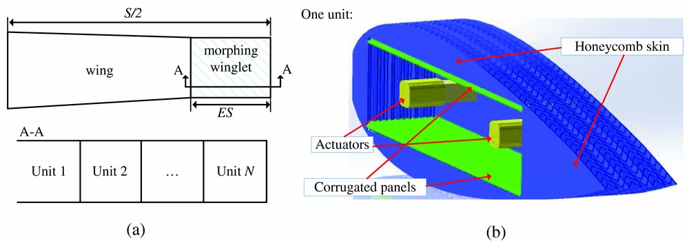
Figure 10. (a) Wing span extension via the morphing winglet, (b) Conceptual design of the morphing winglet.
As shown in Fig. 11, a simple two-level optimisation procedure is applied in this paper. The entire length of the compliant structures ES is assumed to be fixed. The global variable in the first level is the number of compliant structure units, N. Another external input of the optimisation procedure is the distribution of the aerodynamic loads on the wing and the retrofitted wing tip, which will be used to obtain the concentrated forces Pi (i = 1, 2, . . .) on each compliant structure. If the required rotation angle of each compliant structure is also known, the optimisation of each compliant structure is then performed in sequence to obtain the optimum actuation force of each unit, which can be used to size the actuation system, and estimate the associated weight increase.
Figure 11. Optimisation procedure of the multiple units of compliant structures.
In the current study, two optimisation cases are considered. First, a hypothetical case is tested, in which the wing span, S, is 6 m, and the extended length, ES, is fixed at 0.5 m. The aerodynamic load distribution is assumed to be perfectly elliptical and the total lift is 1000 N. The height and the width of each compliant structure is b = 0.1, and w = 0.1 m, respectively. In this case, the objective is the sum of the actuation force in the compliant structures.
Figure 12(a) shows that as the number of complaint structures increases, the sum of the optimum actuation forces is not monotonic, which means for a fixed span extension, a trade-off selection of the length of each compliant structure should be made to reduce the total actuation force.
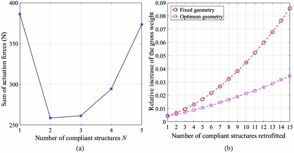
Figure 12. (a) Sum of the optimum actuation forces with a fixed length ES; (b) Optimum weight increase compared to the results a fixed geometry.
The assumption of a fixed-span extension leads to fixed aerodynamic loads, which simplifies the optimisation problem. In contrast, a changing wing span will require both structural and aerodynamic analysis, and hence another optimisation case is performed in a more realistic situation from Ref. Reference Wang, Khodaparast and Friswell16. The basic parameters of the proposed regional airliner are summarised in Table 3 and more details can be found in Ref. Reference Wang, Khodaparast and Friswell16. The compliant structure is used to change the dihedral angle of the morphing winglet in a regional airliner. The length and height of a compliant structure unit is fixed at 0.1 m and 0.101 m, respectively, based on the wing geometry, while the span of the wing changes with the increase of the number of compliant structures. The width of the compliant structure is assumed to be equal to the wing-tip chord, which is overestimated due to the leading and trailing edge. And the aerodynamic loads are obtained using the open software AVL(Reference Drela and Youngren23), which is based on the vortex lattice method. The actuation force of the compliant structure is provided by a worm rack system and the weight of the actuation system is estimated based on the specified actuation force. Analytical expressions have been found to determine the weight increase due to the actuation system, which is proportional to the actuation force.
Table 3 Summary of the basic parameters of the optimisation airliner
The potential performance improvement of morphing winglets will be compromised by the weight increase of the retrofitted structure and actuation systems. While the result in(Reference Wang, Khodaparast and Friswell16) has shown that the relationship between the number of compliant structures and the corresponding performance change, the geometric parameters in that case study were fixed and not optimal. Figure 12(b) shows the relative increase of the gross weight before and after the actuation forces are optimised. In this case, the regional airliner is trimmed at steady level flight when it has the maximum gross weight, and the required rotation angle of each compliant structure unit is 6 degrees. Compared to the previous result, a significantly smaller weight increase can be obtained after the optimisation procedure is applied, which will make the proposed morphing structure more beneficial. For instance, the range of the aircraft in steady flight can be calculated as(Reference Raymer and Schetz24)
 $$\begin{equation}
{\rm{Range}} = \frac{V}{C}\frac{L}{D}{\rm{ln}}\left( {\frac{{{W_i}}}{{{W_f}}}} \right),
\end{equation}$$
$$\begin{equation}
{\rm{Range}} = \frac{V}{C}\frac{L}{D}{\rm{ln}}\left( {\frac{{{W_i}}}{{{W_f}}}} \right),
\end{equation}$$
where Wi , Wf , V, C, L/D are the initial weight, final weight, velocity, specific fuel consumption and the lift-to-drag ratio of the aircraft. With the morphing winglet retrofitted, the range can be increased due to the larger lift-to-drag ratio, which will be partially compromised by the increased weight. For example, if 8 units of compliant structure are retrofitted due to other constraints, the optimisation can improve the range increase from 1.34% to 2.66%.
6.0 CONCLUSIONS
In this paper, a compliant structure based on stiffness asymmetry is investigated. The compliant structure consists of two corrugated panels and the stiffness asymmetry is introduced to induce deformation under the actuation force. The stiffness matrix of the compliant structure is obtained to calculate the deformation, which is verified by detailed finite element analysis and experimental tests. The accurate deflections obtained from the stiffness matrix also make the optimisation of the compliant structure reasonable and much more efficient.
The deflections of the round corrugated panel are obtained when the panel has fixed boundary conditions. A coupling effect between the extension force and the vertical deflection is found. The equivalent stiffness matrix of the corrugated panel is then obtained, which can be used to assemble the matrix of the compliant structure.
The deflections of the compliant structure can be calculated using the stiffness matrix. The results are verified by the detailed finite element analysis under actuation and aerodynamic forces. Three samples were manufactured, and the deformation of the samples was measured from photographs of the deformed structure. The slopes of the lateral and axial deflection are compared between the experimental and analytical results. Analysis of the geometry uncertainty due to the manufacturing process also indicates that the difference between the experimental and analytical results is acceptable. The verification also shows the effects of the stiffness asymmetry can lead to a further deformation if the compliant structure is tailored to have different stiffnesses in its different parts.
After the stiffness matrix of the compliant structure is verified, an optimisation procedure is applied to find the optimum variables of the compliant structure. The optimisation of a single compliant structure shows the optimum variables are compromised to provide a stiffness asymmetry and satisfy the constraints simultaneously. The optimisation is also performed for multiple units of compliant structure used as a morphing winglet. The relationship between the number of units and the objective is found when the length of the entire compliant structure is fixed. A more realistic optimisation case is conducted to obtain the optimum actuation forces for the morphing winglet, which is assumed to be retrofitted to a regional airliner. An improvement is found since the optimisation reduces the actuation forces, which reduces the weight increase due to the retrofitted morphing winglet, and improves the potential benefits brought by the morphing winglet.
ACKNOWLEDGEMENTS
Chen Wang would like to thank the China Scholarship Council (CSC) and the College of Engineering of Swansea University for providing his PhD scholarship.


