
Introduction
The Cambrian sedimentary basin in northern Victoria Land, Antarctica was formed in association with subduction of the palaeo-Pacific plate under the Antarctic continent (Federico et al. Reference Federico, Capponi and Crispini2006, Reference Federico, Crispini, Capponi and Bradshaw2009). The Mariner Group in the Bowers Terrane of northern Victoria Land is important for understanding the generation, evolution and cessation of the basin because it comprises the least metamorphosed, most informative sedimentary strata, containing typical lithologies, key horizons such as unconformities, and proliferous trilobite fossils in the type sections (Cooper et al. Reference Cooper, Jago, MacKinnon, Simes and Braddock1976, Reference Cooper, Jago, Rowell and Braddock1983, Reference Cooper, Jago and Begg1996, Jago & Cooper Reference Jago and Cooper2005, Reference Jago and Cooper2007). Although the general stratigraphic and palaeo-environmental framework has been established since initial mapping of the area (Riddolls & Hancox Reference Riddolls and Hancox1968, Laird et al. Reference Laird, Bradshaw and Wodzicky1982, Laird & Bradshaw Reference Laird and Bradshaw1983, Bradshaw et al. Reference Bradshaw, Weaver and Laird1985), there are many aspects that require new and more detailed approaches to understand the entire basin history. One of these is a detailed sedimentology of the constituent sedimentary units, which act as a foundation in reconstruction of palaeo-environments and in interpretation of the sedimentary history in terms of larger tectonic implications.
This study investigates the depositional processes of the metre-scale cyclic deposits filling the submarine channels in the Cambrian Spurs Formation exposed at the head of the Mariner Glacier, in the southern part of the Bowers Terrane, based on a detailed outcrop observation. These channel-fill deposits are unique in that they consist of metre-scale cycles of breccia and diamictite, which reflect changing characters of gravity flows within a channel. To date, most outcrop exposures of the gravity flow deposits represent deep-sea fan deposits or base-of-slope systems (Elliott Reference Elliott2000, Martinsen et al. Reference Martinsen, Lien and Walker2000, Haughton et al. Reference Haughton, Davis, McCaffrey and Barker2009), and metre-scale cyclic deposits of debris flow within a channel have been rarely reported (Leach et al. Reference Leach, Herbert, Los and Smith1999). Moreover, previous works on the repeated facies in submarine channel deposits focused mainly on the changing characteristics of gravity flows by progressive deposition of sediments, dilution by mixing with ambient water and continuous intake of underlying sediments (Cornamusini & Costantini 1997, Sohn et al. Reference Sohn, Choe and Jo2002). In contrast, this paper deals with a facies change caused by a combination of allogenic and autogenic factors, which has not been considered at this scale. The findings will enhance our understanding of slope-channel systems and give new insight to interpret small-scale cycles appearing in the seismic data. They will also contribute to our understanding of the depositional systems in the Cambrian back-arc basin in the palaeo-Pacific margin of Antarctica.
Geological setting
Palaeozoic sedimentary successions are exposed in the Transantarctic Mountains, which extend across Antarctica from the Weddell Sea to the Ross Sea (Fig. 1). Northern Victoria Land is the Ross Sea-side margin of the Transantarctic Mountains and is composed of three Precambrian to early Palaeozoic tectonic terranes: the Wilson, Bowers and Robertson Bay terranes, from inboard to outboard (Weaver et al. Reference Weaver, Bradshaw and Laird1984, Bradshaw et al. Reference Bradshaw, Weaver and Laird1985) (Fig. 1). The Wilson Terrane consists of high-grade metasedimentary rocks and granitoids. The Bowers Terrane forms a north-west-trending fault-bounded narrow strip (c. 400 km long and 20–30 km wide) and comprises low-grade metasedimentary rocks of siliciclastics, volcanics and carbonates, named stratigraphically as the Bowers Supergroup. The outermost Robertson Bay Terrane consists predominantly of flysch deposits. These three terranes reflect continental arc magmatism (Wilson Terrane), oceanic arc development (Bowers Terrane) and subsequently accreted deep-sea sediments (Robertson Bay Terrane) in the Pacific margin of Gondwana during the Ross Orogeny (Kleinschmidt & Tessensohn Reference Kleinschmidt and Tessensohn1987, Capponi et al. Reference Capponi, Crispini and Meccheri1999, Federico et al. Reference Federico, Crispini, Capponi and Bradshaw2009).
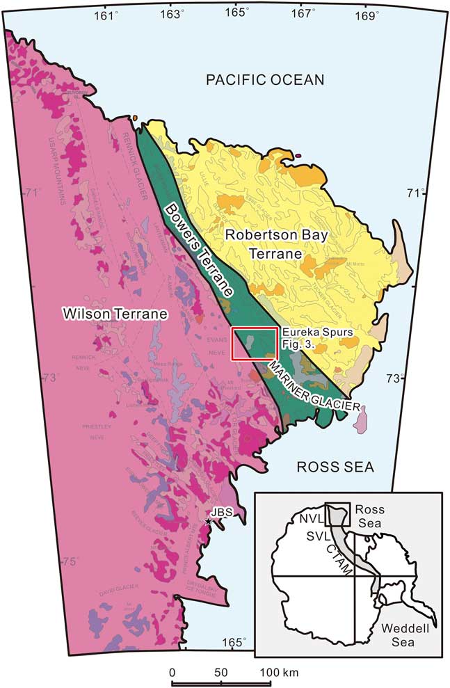
Fig. 1 Location of three tectonic terranes in northern Victoria Land, Antarctica (modified from Läufer et al. Reference Läufer, Lisker and Phillips2011). NVL: northern Victoria Land, SVL: southern Victoria Land, CTAM: central Transantarctic Mountains, JBS: Jang Bogo Station.
The Bowers Supergroup is divided into the Sledgers (c. 3500 m thick), the Mariner (c. 2500 m thick) and the Leap Year (c. 4000 m thick) groups, in ascending order, spanning the Cambrian Series 3 to the Lower Ordovician (Cooper et al. Reference Cooper, Jago, MacKinnon, Simes and Braddock1976, Reference Cooper, Jago, Rowell and Braddock1983, Reference Cooper, Jago and Begg1996, Laird & Bradshaw Reference Laird and Bradshaw1983). The Mariner Group is subdivided into three lithologic units: the Edlin, Spurs and Eureka formations (Laird et al. Reference Laird, Bradshaw and Wodzicky1982). The Edlin Formation (c. 110 m thick) has been identified only in the north-western part of the Bowers Terrane. This formation consists of fine-grained sandstone and mudstone with an oolitic limestone layer, minor thin tuff and conglomerate and reddish mudstone with mud cracks (Laird & Bradshaw Reference Laird and Bradshaw1983), and has a sharp contact with the underlying Glasgow Formation, Sledgers Group. The Edlin Formation, which pinches out eastwards, is overlain by the limestone and mudstone of the Spurs Formation (Cooper et al. Reference Cooper, Jago, Rowell and Braddock1983) (Fig. 2). The Spurs Formation (c. 900 m thick) consists of fissile mudstone, thin beds of fine-grained sandstone, channelized conglomerate bodies and lenses of limestone (Laird & Bradshaw Reference Laird and Bradshaw1983, Bradshaw et al. Reference Bradshaw, Weaver and Laird1985, Cooper et al. Reference Cooper, Jago and Begg1996). The Spurs Formation is conformably overlain by the Eureka Formation (c. 700 m thick), which consists of wavy-bedded sandstone, mudstone with lenses of limestone, brownish-grey quartz sandstone and minor mudstone with trace-fossils and mud cracks (Andrews & Laird Reference Andrews and Laird1976). The coarsening upwards trend from the mudstone-dominated Spurs Formation to the sandstone-dominated Eureka Formation has been interpreted as regression from deeper shelf or platform to shallow marine environments (Andrews & Laird Reference Andrews and Laird1976). The Mariner Group was dated by trilobites and ranges from late Cambrian Series 3 to middle Furongian (Cooper et al. Reference Cooper, Jago, MacKinnon, Simes and Braddock1976, Reference Cooper, Jago, Rowell and Braddock1983, Reference Cooper, Jago and Begg1996, Jago & Cooper Reference Jago and Cooper2005, Reference Jago and Cooper2007, Park et al. Reference Park, Kihm, Woo, Kim and Lee2016) (Fig. 2).
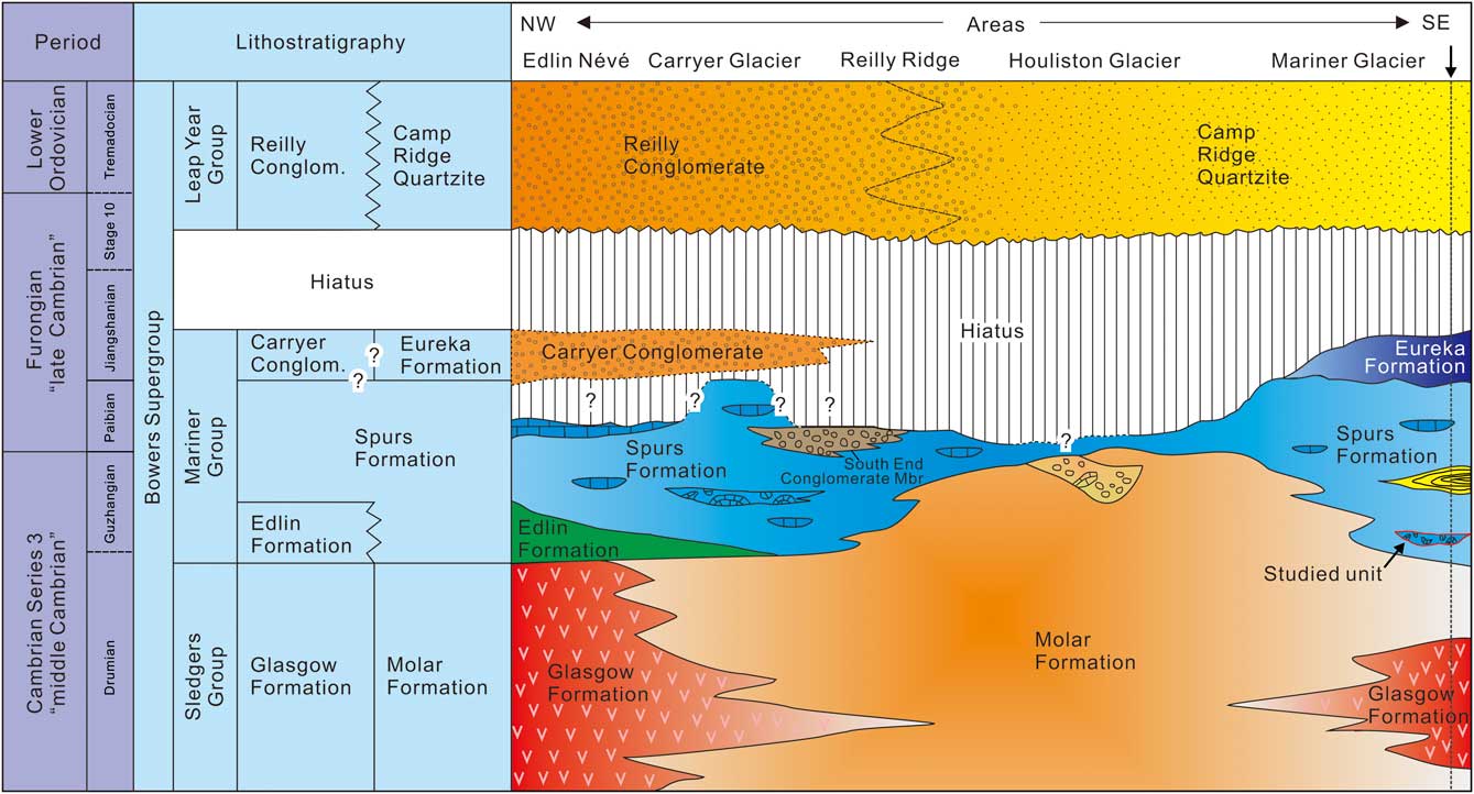
Fig. 2 Stratigraphy of the Bowers Supergroup, with arrows indicating the interval studied. The vertical dashed line near the Mariner Glacier represents the approximate location of the Eureka Spurs section. Modified from Cooper et al. (Reference Cooper, Jago, Rowell and Braddock1983, Reference Cooper, Jago and Begg1996), Laird & Bradshaw (Reference Laird and Bradshaw1983) and Bradshaw et al. (Reference Bradshaw, Gutjahr, Weaver and Bassett2009).
This study deals with the channel deposits in the lower part of the Spurs Formation, which include the channelized conglomerate exposed in the Eureka Spurs at the head of the Mariner Glacier. The Victoria University of Wellington Party of the New Zealand Antarctic Research Programme (NZARP) mapped the head of the Mariner Glacier in November and December 1971 and named the accessible outcrops on the east side of the Mariner Glacier as the Eureka Spur (ERK) 1, 2, 3 and 4 sections (Fig. 3). The party measured the Mariner and Leap Year groups in these sections (c.1600 m in total) and correlated them lithologically (Andrews & Laird Reference Andrews and Laird1976). During the 1974–75 season, the International Geological Correlation Project team discovered Cambrian fossils from the Eureka Spur 3 section (Cooper et al. Reference Cooper, Jago, MacKinnon, Simes and Braddock1976), which subsequent studies suggested were of late Middle Cambrian age (Cooper et al. Reference Cooper, Jago, Rowell and Braddock1983, Park et al. Reference Park, Kihm, Woo, Kim and Lee2016).

Fig. 3 Geological map of the study area, modified from Capponi et al. (Reference Capponi, Meccheri, Pertusati, Carosi, Crispini, Musumeci, Oggiano, Roland and Tessensohn2012). ERK: Eureka Spur.
Methods
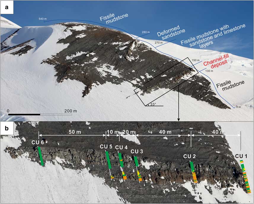
Coarse-grained channel-fill deposits of the ERK 3 section occur in the interval between 130 and 150 m above the base of the exposure (Fig. 4). Two channel-fill bodies are recognized: the lower major one and the upper smaller one. Six vertical sections (named CU1 to CU6) of these channel-fill deposits were measured, spaced laterally 10–50 m (Figs 4b & 5). The six columnar logs were lithologically correlated and were arrayed using the base of the intervening mudstone in the lower channel unit as stratigraphic datum (Fig. 5). Line drawings of the channel-fill deposits were made to depict the 2D geometry of the internal units. A total of 43 rock samples were taken throughout the channel-fill deposits, of which slabs and thin-sections were observed under microscopes. The clasts in breccia and diamictite beds were classified into four types (oolitic limestone, sandstone, micritic limestone and mudstone) and were counted for provenance analysis (Table I) (Fig. 6).

Fig. 4 Photographs of a. the Spurs Formation, and b. the studied intervals in the Eureka Spur 3 section. a. The channel-fill deposit occurs between 130 and 150 m above the base of the exposure. b. Outcrop photograph of the boxed area in a, where six columnar logs were measured. Note that this photograph was rotated by 33° clockwise from the original position.
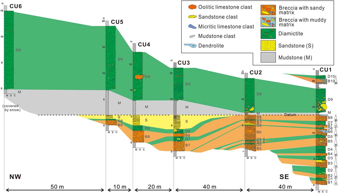
Fig. 5 Columnar description of the channel unit (CU) in Eureka Spur 3. The datum for the correlation is the base of mudstone above the channel unit. M: mudstone, S: sandstone, C: conglomerate.
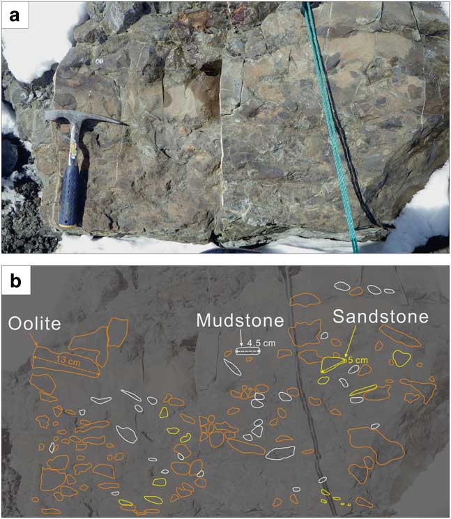
Fig. 6 Example of clast composition counting in CU1 B8. Clasts larger than 1 cm were counted. See Table I for results. a. Outcrop photograph of CU1 B8. b. Line drawing of a. Three types of clasts are recognized and marked by different colours. White: mudstone, orange: oolitic limestone, yellow: sandstone.
Table I Lithologic summary and interpretation of facies in the Spurs Formation.

Sedimentary facies
The channel-fill deposits of the Spurs Formation consist of four sedimentary facies, classified by sedimentary structure, grain size and composition. They are breccia (B), diamictite (D), thin-bedded sandstone (S) and mudstone (M) (Table II).
Table II Result of clast composition counting for breccia and diamictite facies. See Fig. 5 for bed numbers and location.

Facies B: breccia
This facies is represented by clasts- or matrix-supported, unsorted, and disorganized polymictic breccia with fine-grained sandstone and oolitic matrix (Figs 6, 7 & 8). The clasts are composed mainly of oolitic limestone (50%), mudstone (27%), sandstone (18%) and minor micritic limestone (5%) (Table I). Most clasts are oriented randomly in general, but subparallel clasts are observed locally (Fig. 6). The clasts are demarcated by a sharp boundary against the matrix (Figs 9a, b & d). The oolitic limestone clasts, which consist predominantly of well-sorted ooids without micritic matrix (Fig. 10a), are angular to rounded, and dark grey in colour. Some oolitic limestone clasts have planar lamination. The sandstone clasts are subangular to rounded, and brown in colour. The oolitic limestone and sandstone clasts range in size from 1 to 20 cm along the long axis. The mudstone clasts are usually pebble-sized, rounded, and grey to light grey in colour. The micritic limestone clasts are composed mainly of lime mud, with a minor amount of wackestone (Fig. 10b). They are well rounded, and white grey to dark grey in colour. Outsized boulders occur in some breccia beds, which are inversely graded. The lithology of the outsized boulders is variable, including thin-bedded cross-laminated sandstone (Fig. 8b), crudely laminated oolitic limestone (Fig. 8e) and dendrolite (Figs 8c, d & 9c). The matrix is usually composed of ooids smaller than those of the oolitic limestone clasts, fine-grained sandstone and minor muddy material (<10%) (Fig. 10b). Only one bed of breccia (CU1, B10) consists exclusively of muddy matrix (Fig. 8f). Breccia beds range from 40 to 280 cm in thickness. Most thick beds show lateral continuity in the channel but onlap and end abruptly on the north-west channel wall (Fig. 5). This facies is capped by diamictite and mudstone, with a sharp undulatory boundary (Figs 7a & c). The base of this facies is characterized by a sharp boundary scouring the underlying diamictite (Fig. 7b) or fissile mudstone, occasionally showing flute or groove casts.
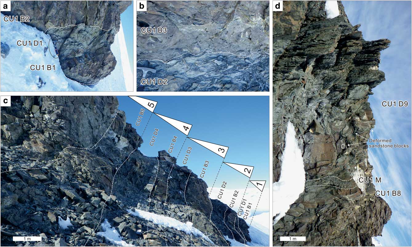
Fig. 7 Representative outcrop photographs of the Eureka Spur 3 section. a. Irregular and sharp contacts between breccia and diamictite. Note the scour structure at the bottom of breccia beds (CU1 B1 and B2) to the underlying fissile mudstone and diamictite. b. Sharp erosional boundary between breccia and diamictite. c. Cyclic succession of breccia and diamictite. d. Thick diamictite bed (D9) containing deformed sandstone, limestone and breccia blocks in the lower part. It also shows a transition from the top of B8 to mudstone. The photographs in a and d were rotated 60° clockwise for better presentation.
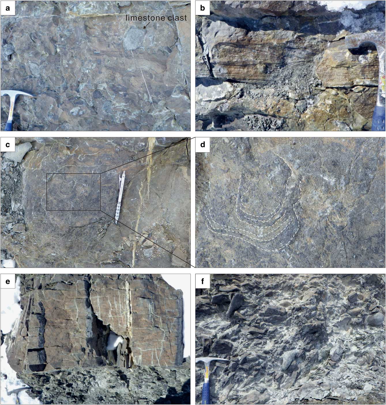
Fig. 8 Representative outcrop photographs of breccia facies in the Eureka Spur 3 section. a. Disorganized polymictic clasts in CU1 B3. b. A cross-laminated sandstone clast in CU2 B7. c. A dendrolite block in CU1 B6. d. A detailed view of a dendrolite clast in CU1 B6. Note the layered structure (dashed line). e. A block of thin-bedded oolitic limestone in CU1 B10. f. Distorted muddy matrix englobing clasts in CU1 B10.

Fig. 9 Representative slab photographs of breccia facies. a. Angular to subangular oolitic limestone clasts (outlined in orange) and angular to rounded mudstone clasts (outlined in white) of CU1 B2. b. Crudely laminated oolitic limestone clasts and oolitic limestone matrix of CU1 B5. c. A slab of dendrolite clasts from CU1 B8, composed of calcified microbial masses (black) with branching structure. d. Rounded sandstone (upper part), crudely laminated oolitic limestone, and dark grey lime mudstone clasts and muddy matrix with fossil fragments; sample from CU1 B10.
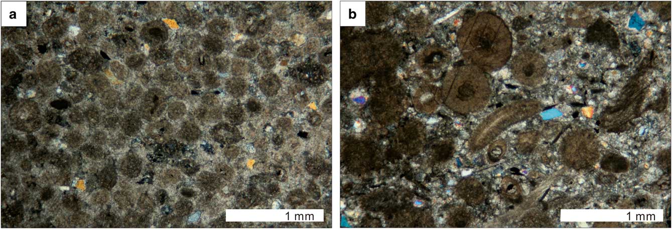
Fig. 10 Photomicrographs of breccia facies. a. Sorted small ooids and angular quartz grains in crudely laminated oolitic limestone clast. b. Poorly sorted ooids, fossil fragments and fine siliciclasts in the matrix. Both samples from CU1 B5.
Unstratified, poorly sorted, massive breccia with disorganized clast- or matrix-supported fabric, floating large clasts and localized inverse grading indicate a debris flow origin (Mulder & Alexander Reference Mulder and Alexander2001, Sohn et al. Reference Sohn, Choe and Jo2002). The sand-dominant matrix and occasional occurrence of subparallel clasts represent cohesionless debris flow whose frictional grain interaction during transportation is the main flow-support mechanism (Mulder & Alexander Reference Mulder and Alexander2001). Ubiquitous clast-supported texture with some inverse grading indicates that active grain interactions, such as collision and friction, which generated dispersive pressure, or kinematic sieving, were dominant mechanisms in the flow (Sohn Reference Sohn2000), although they were not strong enough to develop inverse grading in all parts of the beds (cf. Jullien et al. Reference Jullien, Meakin and Pavlovitch1992). The large clasts could have been lifted by buoyancy resulting from these mechanisms and the strength of interstitial matrix with a small amount of mud (<10%). The erosional lower contact with flute and groove casts is inferred to represent an initial erosional event caused by turbulent flow, which could have developed ahead of the main debris flow (cf. Sohn et al. Reference Sohn, Choe and Jo2002, Fig. 1c). The erosion by turbulent flow was followed immediately by deposition from the main flow, resulting in the breccia facies with the basal inverse grading. The breccia facies consists of angular to subangular polymictic clasts, which indicate the relatively immature nature of the deposit. Although these flows are supported essentially by frictional grain interactions, which usually have a short transportation distance, the presence of mud in the matrix may have played an important role in allowing a long transport distance (Ilstad et al. Reference Ilstad, Elverhøi, Issler and Marr2004, Tripsanas et al. Reference Tripsanas, Piper, Jenner and Bryant2008). Removal of large clasts (oolitic limestone, dendrolite and sandstone blocks) by the buoyant lift from the base of the flow may also have aided in transporting the breccia. The mud clasts of breccia were incorporated through basal plucking of semiconsolidated muds by highly erosive sediment gravity flows.
Facies D: diamictite
This facies includes matrix-supported pebbly to boulderly deposits, which consist of disorganized, poorly sorted clasts and muddy matrix. It occurs in close association with breccia beds and is represented by medium to thick beds (10–140 cm) except for a single bed that measures up to 15 m in thickness (Figs 7a, b & c). The clasts are composed of micritic limestone (45%), sandstone (32%) and oolitic limestone (22%) (Table I) (Fig. 11a, b & c). The clasts are rounded to well-rounded and range from 1 to 20 cm in length. The micritic limestone clasts are usually pebble-sized and consist mainly of lime mud and minor wackestone. Some sandstone clasts have planar lamination or cross lamination, some of which are folded (Fig. 11a). The oolitic limestone clasts are dark grey in colour and the boundary between the clast and the matrix is sharp (Fig. 12a, b & c). In the eastern part of the outcrop (CU1 and CU2), metre-scale deformed blocks of bedded sandstone are concentrated in the lower and middle parts (Figs 7d & 11e) of the thick unit of this facies. Similar-sized blocks of oolitic limestone clasts occur in the middle part of the same unit (Fig. 11f). The matrix consists mainly of silicic mud with c. 10% of fine sand grains and is folded and distorted (Figs 13a & b). This part of the mudstone matrix can be easily distinguished from the fissile mudstone by its rather homogeneous appearance and the lack of strongly developed fissility and foliation. The lower boundary of this facies is sharp, undulatory, but non-erosional to the underlying facies, mostly breccia. The facies is overlain by breccia with a sharp erosional boundary or by sandstone with a sharp undulatory boundary.
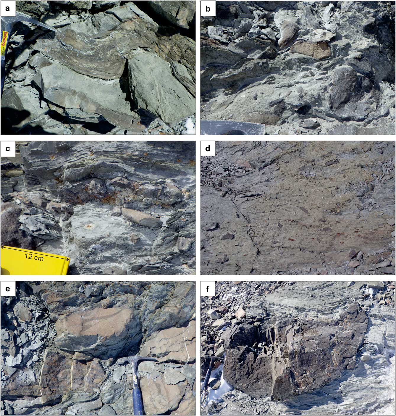
Fig. 11 Representative outcrop photographs of diamictite facies in the Eureka Spur 3 section. a. Folding structures of bedded sandstone clast in CU1 D4. b. Poorly sorted oolitic limestone and sandstone clasts in CU1 D7. c. Undulatory laminated muddy matrix in CU1 D10. d. High proportion of muddy matrix in the upper part of CU1 D9. e. Large deformed sandstone blocks in the lower part of CU2 D9. f. A large oolitic limestone block in the middle part of CU4 D9.
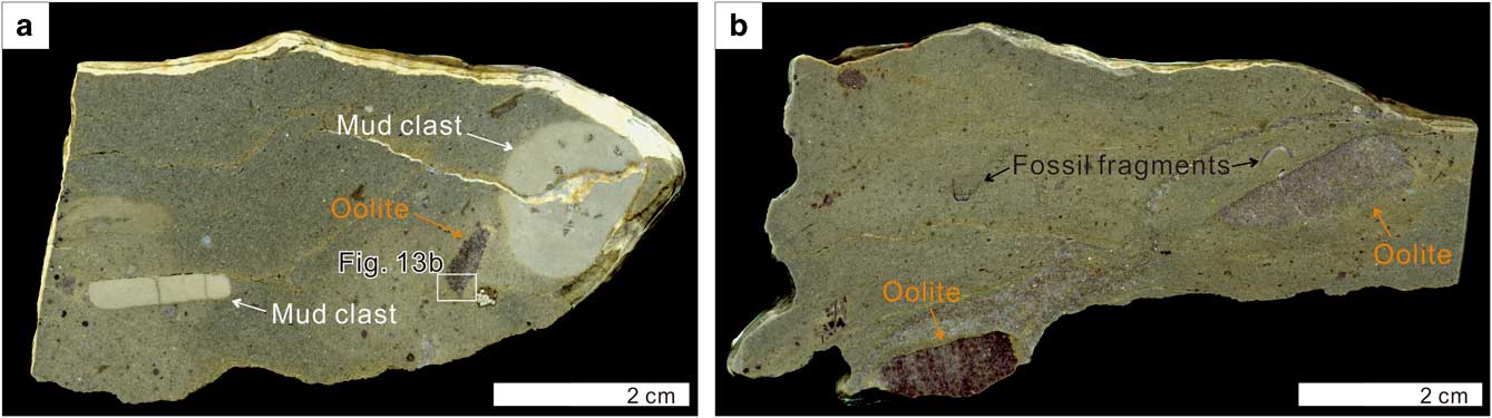
Fig. 12 Representative slab photographs of diamictite facies. a. Small oolitic limestone clasts and variably shaped mud clasts. b. Rounded pebbly oolitic limestone clasts and trilobite fossil fragments. Both samples from CU1 D6.
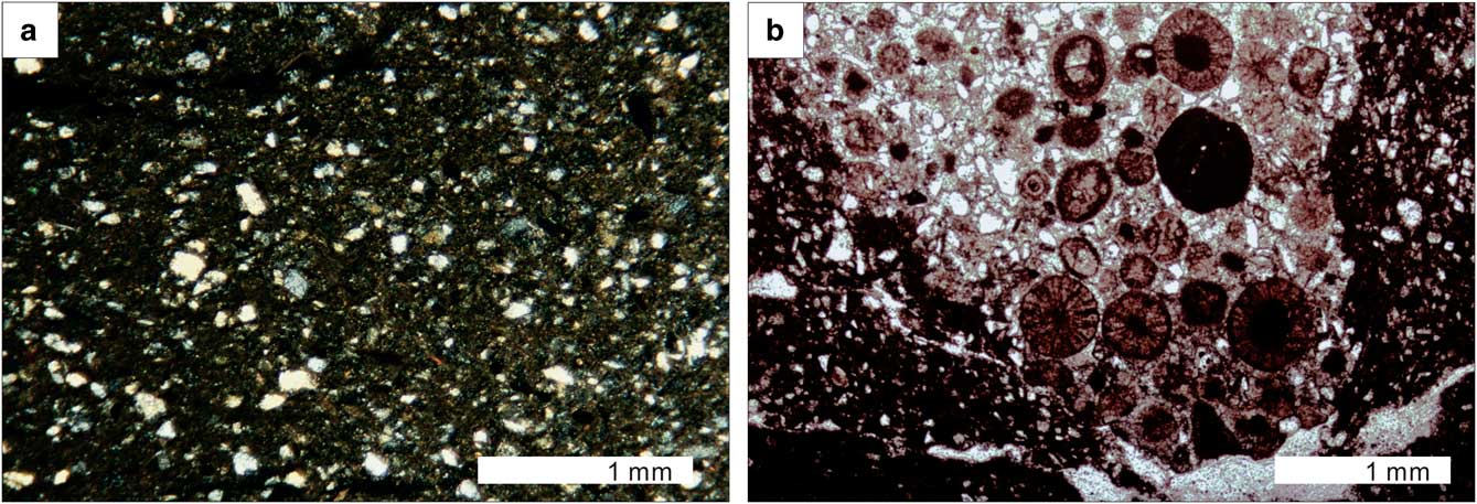
Fig. 13 Representative photomicrographs of diamictite facies. a. Very fine to fine sand-sized quartz grains within muddy matrix (from CU1 D5). b. Sharp boundary between small oolitic clast and muddy matrix (from CU1 D6).
The matrix-supported texture, disorganized clast fabric, partly developed inverse grading and large floating clasts indicate deposition from cohesive debris flow (Sohn et al. Reference Sohn, Choe and Jo2002, Haughton et al. Reference Haughton, Davis, McCaffrey and Barker2009). Angular rafts of heterolithic clasts indicate that there were plugs within the debris flow. The lack of organized clast fabric may be a result of a lack of active clast interactions or pervasive shear straining of the debris flow materials, which can align or imbricate the constituent clasts. The absence of erosional features and the high proportion of muddy matrix are indicative of cohesive behaviour of the flow (Mulder & Alexander Reference Mulder and Alexander2001). The deformed sandstone, micritic limestone and blocks of breccia at the base of the thick diamictite bed most likely originated from unstable channel walls, and indicate high viscosity of the chaotic muddy flow (Tripsanas et al. Reference Tripsanas, Piper, Jenner and Bryant2008). The folded and distorted matrix indicates the preservation of the original deformation structure of the channel wall sediment in the low shear area of the flow, or partial deformation in the laminar flow.
Facies S: thin-bedded sandstone
This facies is represented by thin-bedded medium-grained sandstone. The beds are generally massive, although some part shows crude planar lamination and grading (Figs 14a, b & c). It also shows ductile deformation features such as small-scale folds and boudinages. This deformation sometimes develops into reverse faults. The beds show a lateral variability in thickness and even pinch out. This facies is interbedded by a few centimetre-thick structureless mudstone layers and forms a facies succession. The relative amount of mudstone interbedded in the succession increases gradually upwards, along with a thinning-upwards trend of sandstone. The lower boundary of this facies is characterized by a sharp contact to the underlying diamictite.
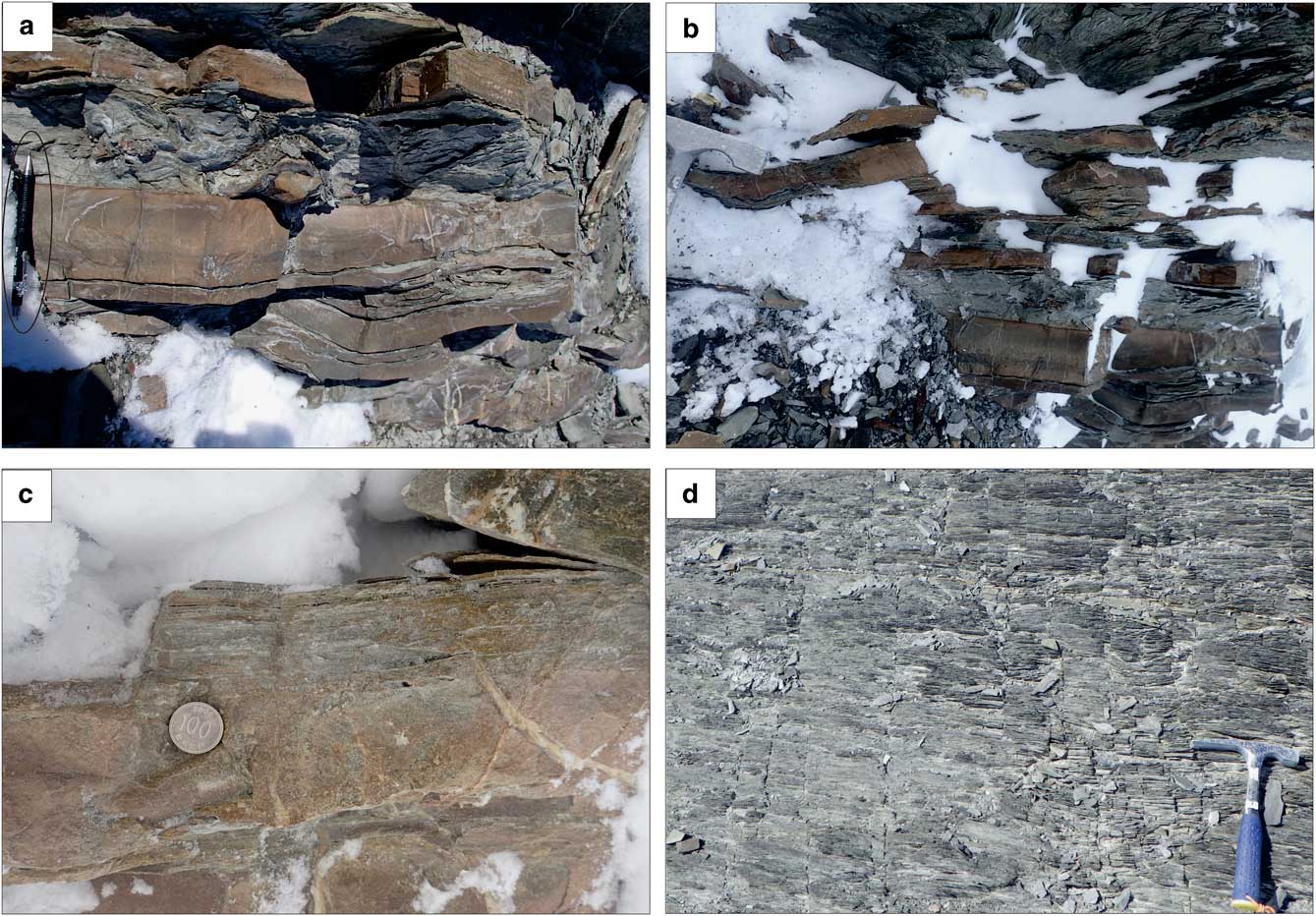
Fig. 14 Representative outcrop photographs of sandstone and mudstone facies in the Eureka Spur 3 section. a. Alternation of deformed thin-bedded sandstone and distorted mudstone in CU3 S. b. Thinning-upwards trend of the sandstone facies succession in CU3 S. c. Medium-grained sandstone grading up into fine-grained sandstone in CU3 S. d. Laminated mudstone in CU3 M.
This thin-bedded sandstone is interpreted as a deposit from high to low density turbidity currents. Massive to normally graded medium-grained sandstone beds are attributed to rapid deposition by direct suspension settling. The planar laminated beds are produced by traction current formed by relatively low density currents (Talling et al. Reference Talling, Masson, Sumner and Malgesini2012). The thinning and muddier upwards trend of the facies succession suggests a gradual decrease in the amount of transported sediments or in depositional energy. The structureless mudstone alternating with sandstone beds may be deposits from the dilute tail of the flow and suspension setting.
Facies M: mudstone
This facies is represented by brownish grey homogeneous to crudely laminated mudstone (Fig. 14d). It displays strong foliations whose orientations are oblique to the primary bedding plane. The mudstone beds occasionally include small clasts (<1 cm) of oolitic limestone or sandstone. The lower boundary is in sharp contact with the underlying breccia or sandstone. The facies is capped by the overlying diamictite or breccia, with a sharp undulatory boundary.
The lamination in this facies is interpreted to have originated from the muddy suspension in the tail of turbidity currents (Kneller & McCaffrey Reference Kneller and McCaffrey2003, Stevenson et al. Reference Stevenson, Talling, Masson, Sumner, Frenz and Wynn2014). The homogeneous to crudely laminated characters of the facies are reminiscent of the Bouma “e” division (Te) of a turbidite, which is formed by suspension settling. The presence of small clasts suggests that there could be thin amalgamated and cryptic cohesive debris flow units in the mudstone facies. The sharp basal contact indicates the bypassing of low density of fine-grained sediment particles from waning depletive flows (Stevenson et al. Reference Stevenson, Talling, Masson, Sumner, Frenz and Wynn2014).
Architectural elements
Two architectural elements were defined on the basis of large-scale stratal pattern and constituent facies. They are herein named as hollow-fill (HF) and sheet-like (SL) elements. Each element represents genetically related sedimentary processes and their spatial arrangements (Di Celma et al. Reference Di Celma, Cantalamessa, Didaskalou and Lori2010, Hubbard et al. Reference Hubbard, Fildani, Romans, Covault and McHargue2010, McHargue et al. Reference McHargue, Pyrcz, Sullivan, Clark, Fildani, Romans, Covault, Levy, Posamentier and Drinkwater2011).
Hollow-fill element: HF
The HF element is a sedimentary body with a concave-up base and flat upper surface, resting on a stepwise erosional base (Table III) (Fig. 15). This element is up to 120 m wide and 13.5 m deep. Two HFs, namely the lower and the upper HFs, are recognized in the Spurs Formation. The lower HF consists of cyclic deposits of breccia and diamictite beds and a locally developed shallow channel body of thin-bedded sandstone. The boundary between each cycle is sharp and erosional, whereas the internal boundary of the cycle, the base of diamictite facies, is sharp but non-erosional. The breccia forming the lower part of the cycle is thicker than the overlying diamictite. A total of eight cycles are recognized (CU1 in Fig. 5), which range from 0.55 to 3.3 m in thickness, with an average thickness of 1.8 m. These cyclic deposits form flat horizontal bodies that are continuous in the channel but onlap or pinch out towards the channel wall. The cyclic deposits incise into the underlying mudstone and the diamictite at the top of the preceding cycle, whereas the diamictites tend to be confined within the lateral extent of the underlying breccia. The locally developed shallow channel body of thin-bedded sandstones can be identified only in CU3, 4 and 5. It is c. 50 m wide and 0.3–2.7 m thick. The upper HF is 1.6 m thick and c. 20 m wide and comprises one cycle of breccia and diamictite (B10 & D10 in Fig. 15). The breccia of the upper HF consists of muddy matrix and includes an oolitic limestone block, which retains primary structure such as planar bedding. The diamictite of the upper HF is composed predominantly of mud (>90%), with scarce pebble-sized clasts.
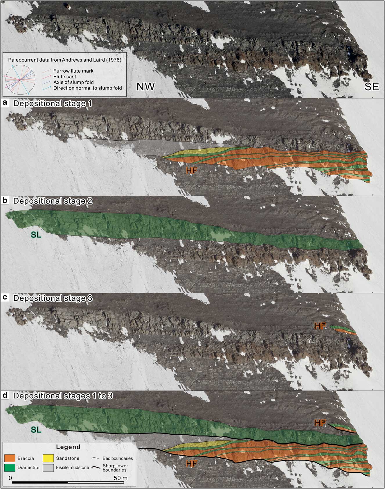
Fig. 15 Architectural elements and depositional stages. HF: hollow-fill element, SL: sheet-like element. See Fig. 4 for original outcrop photograph. Note that the photograph was rotated by 33° clockwise to align the channel unit to the horizontal orientation.
Table III Classification and interpretation of architectural elements in the Spurs Formation.

The hollow-fill architectural element is interpreted as gravity flow deposits filling erosional channels, formed by pulses of mass movement. The very sharp and erosive lower boundary of HF indicates an initial erosional event caused by a turbulent flow that was capable of metre-scale erosion (c. 1–3 m incisions). The active incision events resulted in stepwise widening of the channel. Once an initial erosional trail had been made, the intermittent gravity flows followed the trail, widening and filling it. This process formed cyclic successions, which are interpreted as repetition of submarine cohesionless debris flow deposits (breccia) and following cohesive debris flow deposits (diamictite). The simple flat internal geometry of HF in the lower part of the channel is ascribed to the relatively straight form of the channel. Local development of sandstone succession in the upper part of the channel fill suggests possible geomorphological control and sinuous channel development when the channel becomes wider in the later stage. The fining-upwards facies of the channel sandstone deposits is suggestive of a deposition by low-density turbidity currents with progressive decreases in depositional energy.
The isolated channel-fill debris flow deposit (the upper HF) consisting of muddy breccia and diamictite represents a small channel upstream, which is probably active for a relatively short period and then generally abandoned (Payros et al. Reference Payros, Pujalte and Orue-Etxebarria2007). The upper HF is in many respects similar to the lower HF, but differs in that it represents a less energetic flow, which deposited the thinner, breccia bed with muddy matrix, and resulted in less intense basal erosion.
Sheet-like element: SL
This element has a wide, continuous body with a flat base and a slightly convex-up upper boundary. Despite the limited exposure of the element in the studied section, it is wider than 120 m and thickens westwards from c. 4.5 m to 15 m (Fig. 15). This element consists of a massive single bed (D9) of diamictite. The lower part of the element in CU1 and CU2 shows an inverse grading of polymictic blocks with folded structures. The blocks are variable in shape and range from a few centimetres to metres in length. The matrix is characterized by fine-grained and crudely laminated mud, which is folded and distorted in some part. The lower and upper boundaries of this facies are characterized by sharp undulatory contacts.
The convex-up sheet-like body associated with pelagic mudstone is suggestive of deposition in a lobe on a relatively flat unconfined seafloor (Bernhardt et al. Reference Bernhardt, Jobe and Lowe2011). A lack of erosional surface at the base of the element and a relatively high proportion of muddy matrix suggest a cohesive debris flow origin (Mulder & Alexander Reference Mulder and Alexander2001). Generally thicker (4 m to tens of metres) cohesive debris flow deposits are relatively common on the proximal part of the base slope (Cornamusini et al. Reference Cornamusini, Elter and Sandrelli2002, Tripsanas et al. Reference Tripsanas, Piper, Jenner and Bryant2008). A single occurrence of the debris flow lobe may have been formed by a non-cyclic event such as an earthquake. This element may have been formed by backfilling of the channel (Pickering et al. Reference Pickering, Hodgson, Platzman, Clark and Stephens2001).
Depositional stages
The development of submarine channel deposits in the Spurs Formation can be explained in three stages (Fig. 15). Stage 1 is represented by the lower channel-fill deposits (lower HF). They were formed in the initial phase of stage 1 by channel-wide erosion and transport of sediments to the areas further downslope. The turbulent flow widened the channel by eroding the underlying and surrounding muddy sediment. After erosion, the channel was subsequently filled by the HF deposits (the cyclic deposits of breccia and diamictite). This deposition tends to have generated repeated fining-upwards sequences from breccia to diamictite. At the end of stage 1, the channel became progressively shallower and overfilled. The relatively low-energy sandy turbidity current, flowing along the local depressions of the channel, formed the thinning- and fining-upwards sandstone sequence in the upper left corner of the lower HF. Such turbidities are commonly observed at the final stage of submarine channel-fill sequences. The channel is a type of erosional channel in which the flow is confined to the channel itself. Lack of any evidence of spill-out deposits in the Spurs Formation suggests that gravity flow in the channel was volumetrically smaller than the channel, or diluted flow was not developed in the upper part of the flow because of either coarse grain size or the cohesiveness of the flow.
Stage 2 is represented by submarine lobe deposits (SL) consisting of very thick diamictite. The flat-based diamictite body is interpreted as unconfined equivalents of the diamictite of the channelized elements (HF), formed after the overfilling of the previous channel. High-strength debris flows tend to produce relatively thick clast-rich debrites that extend back nearly to the site of the original slope failure. Large boulders are usually concentrated at the head and on the lateral margin of the flow body. Deformed sedimentary blocks representing slump folding in the diamictite may have been produced by the collapse of unstable channel walls during failure, which transformed into muddy debris flows.
The upper HF represents the final stage. The small-scale HF consists of a single cycle of muddy matrix breccia and diamictite, which is represented by the exposure of a small channel fill c. 20 m wide. The smaller size of the channel body and the more frequent occurrence of sandy interbeds in the background sediment around the upper HF are indicative of the proximity to the source area of the channel system.
Discussion
Source area of the breccia and diamictite of the Spurs Formation
Andrews & Laird (Reference Andrews and Laird1976) postulated that the Mariner Group was deposited in an open marine, probably low-gradient shelf or platform environment. According to their depositional model, ample siliciclastic sediments were supplied from the adjacent fluvial system represented by fluvial sediments in the Camp Ridge Quartzite of the Leap Year Group, and accumulated under intertidal and subtidal settings (Red Bed Unit of the Eureka Formation) (Andrews & Laird Reference Andrews and Laird1976). The wavy-bedded sandstone and associated limestone units of the Eureka Formation represent shelf or platform sedimentation. In deeper parts of shelf and slope environments, fissile mudstone and conglomerate were deposited in the channel (Spurs Formation).
It was also demonstrated that the channel deposit of the Spurs Formation was oriented NE–SW (Andrews & Laird Reference Andrews and Laird1976, fig. 4). This interpretation is in accordance with the erosional features observed at the base of the breccia in this study, which generally indicates a palaeoflow direction of NE–SW. In contrast, the orientation of the fold axis of the slump-folded sandstone in the channel indicates slumping from the north-west (Andrews & Laird Reference Andrews and Laird1976, fig. 4). This discrepancy in the direction of palaeoflows may suggest that the breccia and the diamictite had different source areas. The sandstone, oolitic limestone and dendrolite clasts together with the abundant ooids in the matrix of the breccia indicate that they originated from the shelf or shelf margin, and the diamictite was formed by muddy debris flows initiated on the steep channel wall so that the slumped blocks from the channel wall were transported into the main channel and incorporated into the cohesive debris flow. The slumped blocks were transported without disintegration as a plug of the debris flow, and thus the orientation of the fold axis of the folded sandstone clasts did not change during transportation.
A model for the genetic process of the breccia and diamictite cycle
The formation of the cycle in the submarine channel can be explained by a simple model with two phases (Fig. 16). The initial phase involves channel-wide erosion by a turbulent flow and deposition of breccia within the channel. The flow was initiated by failure of the shelf-edge and upper slope where limestone and semi-consolidated sandstone were accumulated. The initial erosive flow with high inertia bypassed the channel and headed into deeper water and resulted in a single-stepped or terraced erosional surface with steep-sided walls. The erosion was followed immediately by deposition (breccia) of the cohesionless debris flow, with highly concentrated sediments containing the sandstone and limestone clasts. This produced thick deposits, c. 1–3 m thick, but the breccia did not fill up the channel, leaving some space with steep walls. The second phase is represented by deposition of debris flow in the unfilled channel, which caused an abrupt facies change in the cycle; i.e. from breccia to muddy diamictite. The steep channel walls consisted of muddy sediment, being inherently unstable, which led to a failure resulting in a mass flow. This mass flow is a form of slump consisting of muddy and cohesive matrix, which progressively fills the channel. This flow eventually moves along the channel but the slumped blocks may retain their first sense of motion as a form of the slump folding (Andrews & Laird Reference Andrews and Laird1976). The repetition of phases 1 and 2 resulted in the metre-scale fining-upwards cycles, which occurred eight times in the lower HF and once in the upper HF.
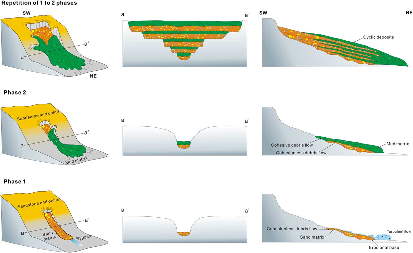
Fig. 16 A model for deposition of the cyclic channel-fill in the Spurs Formation.
Factors affecting the initial generation of the channel are probably those causing slope instability, such as tectonic activity, cyclic loading by strong wave action and over-steepening of sediments, associated with relative sea-level changes, climatic changes and catastrophic river discharge (Posamentier & Allen Reference Posamentier and Allen1993, Di Celma et al. Reference Di Celma, Cantalamessa, Didaskalou and Lori2010, Talling et al. Reference Talling, Malgesini and Felletti2013). The occurrence of gravity flow deposits is restricted to the lower part of the Spurs Formation, where the basinal mudstone facies changes gradually into a more sandy, slope facies. The absence of any sedimentary structures formed by distal gravity flow (e.g. sharp based laminae or beds of thin sandstone and mudstone) in the lower part suggests that the generation of gravity flow in this basin was rather eventual, probably related to such tectonic events as earthquakes. The channel in the Spurs Formation was developed on the continental slope of the back-arc basin, and the depositional age of the Spurs Formation coincides with that of active accretion and magmatism (Federico et al. Reference Federico, Crispini, Capponi and Bradshaw2009, Rocchi et al. Reference Rocchi, Bracciali, Di Vincenzo, Gemelli and Ghezzo2011). The relatively thin shelf facies in the Spurs Formation (wavy-bedded sandstone and limestone unit of Andrews & Laird Reference Andrews and Laird1976) suggests that the basin had a narrow continental shelf. Therefore, initiation of lower HF, upper HF and SL may have been due to earthquakes influencing different types of slope margins, resulting in different types of gravity flows and deposits. This interval may be indicative of a short-lived seismically active period in the basin or a small window for the seismically induced sedimentary structures preserved in the middle of a prolonged active period.
Although the initiation of each channel formation was probably a result of seismic activity, triggering of the cohesive debris flow that formed the diamictite is not easily explained in the same way because the cycle seems to be a result of more regular environmental changes. Considering the characteristics of the shelf in the back-arc basin, sea-level changes or climatic cycles may have been a major factor in triggering gravity flow and supplying shelf sediment to the channel. All these factors are allogenic and could have triggered the cohesionless debris flow of phase 1. However, the depositional controlling factor of the diamictite, which is overlying the breccia in the cyclic deposit, is hard to explain by allogenic processes. The deposition of the diamictite may have been initiated by local slope instability, such as channel wall collapse, which originates within the channel system. Therefore, the abrupt vertical transitions from breccia to diamictite in each cycle can be interpreted as autogenic processes of the channel system (Fig. 16, phase 2). This is the first documentation of the case in which both allogenic and autogenic factors play a role in forming a debris flow system.
The succession of the gravity flow deposits indicates spatio-temporal change of multiphase flow, forming a gradational or sharp transition between each flow (Fig. 17). Sohn et al. (Reference Sohn, Choe and Jo2002) documented a multiphase flow event consisting of turbidity currents, hyperconcentrated flows and cohesive debris flows. It is caused by progressive dilution of a parental debris flow. The dilution of flow originates from repetitive detachment and disintegration of gravel-rich fronts of a hydroplaning debris flow. The resulting deposit is characterized by clast-supported pebble- and cobble-conglomerate with prominent normal grading in the lower part, changing gradually into loosely clast-supported or matrix-supported pebble-conglomerate in the upper part (Fig. 17b) (Sohn et al. Reference Sohn, Choe and Jo2002). In contrast, in this study the transition between the cohesionless debris flow and cohesive debris flow deposits is distinct (Fig. 17a). The matrix composition does not change significantly in the model of Sohn et al. (Reference Sohn, Choe and Jo2002) (Fig. 17b), whereas the succession of our study shows abrupt change in matrix composition from sandy to muddy. Similar change has been reported from hybrid event beds (Haughton et al. Reference Haughton, Davis, McCaffrey and Barker2009, Cornamusini Reference Cornamusini2012) (Fig. 17c), whose sequence was formed by a gravity flow evolving progressively from non-cohesive flow (lower turbidite sandstone) to cohesive flow (overlying debrite) as it moved down-dip. It is interpreted to be the result of continued runout of a debris flow following partial transformation to a forerunning turbidity current (Haughton et al. Reference Haughton, Davis, McCaffrey and Barker2009). The facies transition in the resulting deposit tends to depend on the flow length. In the case of long distance transportation, the facies transition is more transitional, reflecting gradual change from non-cohesive to cohesive flows because the flow head would have stretched away from the flow tail, forming an intervening zone, and the turbulent flow head would have passed rearwards into the intervening zone of clay-induced turbulence suppression. In the case of short distance transportation, the facies transition results in sharp contacts as a result of insufficient time or space to develop longitudinal segregation of components. This hybrid flow and the deposits are important in deep-water fan systems but they rarely occur in channel systems (Haughton et al. Reference Haughton, Davis, McCaffrey and Barker2009). The hybrid beds originated from the original failure, with turbidity currents outpacing debris flows from which they formed via partial flow transformation in the deep-water fan system. The breccia–diamictite succession of the Spurs Formation is apparently similar to the short-distance case of the hybrid flow (Fig. 17a & c). Apart from these hybrid flows, to which the partial flows are strongly genetically related, those in the Spurs Formation are more or less independent, although erosion of the forerunning flow (phase 1) caused slope instability for the generation of the cohesive debris flow.
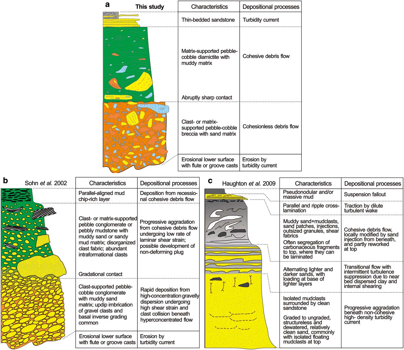
Fig. 17 Comparison of the synthetic debris flow deposits. a. Schematic log model of this study showing abrupt sharp contact between lower cohesionless debris flow and upper cohesive debris flow. b. Gradational contact between lower hyperconcentrated flow and upper cohesive debris flow (Sohn et al. Reference Sohn, Choe and Jo2002). c. Model of the hybrid event bed, showing a transitional flow zone between the lower non-cohesive high-density turbidity current and the upper cohesive debris flow (Haughton et al. Reference Haughton, Davis, McCaffrey and Barker2009).
Conclusion
The architectural elements of the submarine channel-fill deposit in the Spurs Formation include hollow-fill and sheet-like elements that were formed through three depositional stages. The first stage involved channel erosion and hollow-fill deposition by debris flows. The second stage included non-channelized deposition of very thick diamictite over the fully buried channel. The third stage involved small-scale channel erosion and a channel fill, which occurred in the proximal part of the slope depositional system. Metre-scale cyclic succession is prominent in the channel fill deposits. It comprises the lower breccia and the overlying diamictite, which represent cohesionless debris flow and cohesive debris flow, respectively. The triggering mechanism of each cycle may have been repeated allogenic processes (e.g. tectonic activity, eustatic sea-level changes, climatic changes and sediment flux changes), which would have caused instability and failure in the slope margin. In contrast, the abrupt vertical change from breccia to diamictite in each cycle may have been caused by an autogenic process, such as the collapse of steep channel walls and concurrent generation of muddy cohesive debris flow. It is noteworthy that the interaction of allogenic (triggering mechanism of cycle deposit) and autogenic factors (vertical change in each cycle) resulted in the unique channel-fill deposit by debris flows in the submarine channel.
Acknowledgements
This research is part of the project ‘Crustal evolution of Victoria Land, Antarctica and formative process of planets (PM17030, KOPRI)’, funded by the Ministry of Oceans and Fisheries, Korea. Constructive and critical comments from G. Cornamusini and two anonymous reviewers improved the article. We are grateful to Dr Changhwan Oh, Mr Insung Yoo, Mr Sangbum Park, Mr Myung Hwan Kim, Mr Kwanjae Kim, Mr Minho Lee, Mr Myeongho Seo and Mr Sangwoo Han for their support in the field and camp life in Antarctica.
Author contributions
Lee and Woo designed the Korea Antarctic Expedition to northern Victoria Land. Stratigraphic data were collected by Kim, Woo, Park and Kihm. The sedimentological interpretations were made by Kim, Woo and Choe. The article was written by Kim and Woo, with contributions from Choe and Park.