Halloysite is typically formed by hydrothermal alteration and weathering of aluminosilicate minerals. It occurs in association with dickite, kaolinite, montmorillonite and other clay minerals (El Amrani El Hassani & Sadik, Reference El Amrani El Hassani and Sadik2016). According to the enthalpy of formation, kaolinite would be the most stable kaolin mineral (ΔH f = −4115.30 kJ/mol, ΔG f = −3793.93), followed by dickite (ΔH f = −4099.80 kJ/mol, ΔG f = −3777.30) and halloysite (ΔH f = −4092.93 kJ/mol, ΔG f = −3771.95) (Blanc et al., Reference Blanc, Piantone, Lassin and Burnol2006); this might explain the scarcity of halloysite. Depending on humidity, halloysite occurs naturally in two different forms (Joussein et al., Reference Joussein, Petit, Churchman, Theng, Righi and Delvaux2005): the hydrated form (n = 2), in which the sheets are separated by a layer of water has a basal spacing, d 001, of 10 Å; and meta-halloysite, which is the more common form, with an interlamellar distance close to 7.15 Å, similar to kaolinite. The latter is obtained by irreversible dehydration of the 10 Å halloysite at a temperature between 60 and 100°C (Ruiz-Hitzky et al., Reference Ruiz-Hitzky, Ariga and Lvov2008). Deciphering between kaolinite and halloysite forms based on XRD traces only is challenging, and requires some morphological observations to be definitive (Singer et al., Reference Singer, Zarei, Lange and Stahr2004; Joussein et al., Reference Joussein, Petit, Churchman, Theng, Righi and Delvaux2005).
A hollow tubular structure is the predominant and chemically stable form of halloysite. The tubular shape of halloysite is different from the hexagonal platelets of kaolinite, giving it the capability to retain water (Bain, Reference Bain1971; Caillère & Hénin Reference Caillère and Hénin1982; Bailey, Reference Bailey and Bailey1988; Pasbakhsh et al., Reference Pasbakhsh, Churchman and Keeling2013). The tubes have multi-layer walls with positively charged Al-OH groups on the inner surface and negatively charged Si-OH groups on the outer surface (Shchukin et al., Reference Shchukin, Price, Sukhorukov and Lvov2005).
Halloysite has several industrial applications (Zhou & Keeling, Reference Zhou and Keeling2013; Schroeder & Erickson, Reference Schroeder and Erickson2014; Churchman et al., Reference Churchman, Pasbakhsh and Hillier2016), particularly in the ceramics industry and there is an increasing demand for this raw material (Detellier & Schoonheydt, Reference Detellier and Schoonheydt2014; Pracejus et al., Reference Pracejus, Abbasi, Al-Khirbash and Al-Aamri2017). Recently, several studies have attempted to increase the number of applications of halloysite, e.g. as support for catalysts and other functional materials due to its specific morphology and properties (Lu et al., Reference Lu, Wang, Lu, Li and Wang2016). It is also capable of storing a large quantity of hydrogen molecules (Jin et al., Reference Jin, Zhang, Ouyang and Yang2014), drugs for medical purposes (Lvov et al., Reference Lvov, Shchukin, Mohwald and Price2008; Yuan et al., Reference Yuan, Southon, Liu and Kepert2012; Tan et al., Reference Tan, Yuan, Annabi-Bergaya, Liu, Wang, Liu and He2014), of forming antibacterial biological membranes (Chen et al., Reference Chen, Zhang, Liu, Zhang and Wang2012; Zhang et al., Reference Zhang, Chen, Zhang, Zhang and Liu2013; Jin et al., Reference Jin, Zhang, Ouyang and Yang2014) and polymer-based composites (Zhou et al., Reference Zhou, Guo, Liu, Liao, Rabie and Jia2010; Pan et al., Reference Pan, Yao, Xu, Ou, Huo, Li and Yan2011; Abdullayev et al., Reference Abdullayev, Abbasov, Tursunbayeva, Portnov, Ibrahimov, Mukhtarova and Lvov2013; Tan et al., Reference Tan, Yuan, Annabi-Bergaya, Liu, Wang, Liu and He2014) among other technological uses (Williams & Hillier, Reference Williams and Hillier2014). Halloysite is also a major adsorber of cationic and anionic molecules (Abdullayev & Lvov, Reference Abdullayev and Lvov2010; Luo et al., Reference Luo, Zhao, Zhang, Liu, Yang and Liu2010; Zhao et al., Reference Zhao, Zhang, Zhang, Wang, Liu and Chen2010a,Reference Zhao, Zhang, Zhang, Wang, Liu and Chenb).
In Morocco, halloysite deposits are located in the northeastern Nador region (El Amrani El Hassani & Sadik, Reference El Amrani El Hassani and Sadik2016). Within the Gourougou area, a large Middle Miocene–Late Pliocene volcanic deposit is located in the Maazza Valley (Fig. 1). The halloysite deposit occurs in thin layers (decimetric) in contact with a reef limestone, cinerites and volcanic gravels. In spite of the scientific and economic interest in this natural resource, few investigations of Morocco's halloysite deposits have been done, compared to other countries, although several geological studies have been undertaken in the region (Jeannette et al. Reference Jeannette, Monition and Ortelli1958; Martin Vivaldi & Gírela Vilchez, Reference Martin Vivaldi and Gírela Vilchez1958; Gírela Vilchez, Reference Gírela Vilchez1961; Azdimousa, Reference Azdimousa1991). From the point of view of sedimentology, Martin Vivaldi (Reference Martin Vivaldi1961) suggested that the Maazza deposits consist of a mixture of endellite, halloysite, gibbsite, montmorillonite and alunite, probably of hydrothermal origin.

Fig. 1. Location (a) and geological map of the study area indicating the prospected area (b).
The main aim of this study was to describe the halloysite deposit and to update our knowledge of the geological context, the mineralogical composition and its physico-chemical and thermal properties. Furthermore, the various properties necessary to assess halloysite in terms of ceramics applications were investigated.
MATERIAL AND METHODS
Materials
The halloysite deposit is located in the southern part of the Neogene basin of Melilla (NE Morocco), at the foot of the Gourougou volcano in the Maazza Valley (N: 35°16'43.751″ W: 3°01'20.865″) (Fig. 1). The Melilla Basin is related to the main orogenic movements of the Rif domain during the Middle Miocene (Choubert et al., Reference Choubert, Charlot, Faure-Muret, Hottinger, Marcais, Tisserant and Vidal1968, Guillemin & Houzay, Reference Guillemin and Houzay1982). The opening of this basin is related to strike-slip faulting which marks the eastern limit of the Alboran basin, following the tectonic directions established during the collision of internal zones of the Rif Domain (García-Dueñas et al., Reference García-Dueñas, Balanyá and Martínez-Martínez1992). The Melilla Basin is generally characterized by three major sedimentary cycles: (1) Upper Tortonian marls associated with volcanism; (2) Messinian sediments unconformably overlying the Tortonian deposits, reflecting an open-sea environment with normal salinity; (3) Early Pliocene sediments corresponding to a shallow-marine incursion during the late Messinian seawater evaporation.
The halloysite deposit belongs to the Neogene basin, located at the base of the Messinian series, between marl with a reef-like appearance in the study area, cinerite and red volcanic rounded gravel of mm-sized fragments from the Gourougou volcano (Guillemin & Houzay, Reference Guillemin and Houzay1982). The clay forms clusters or irregular lenses in contact with a travertine situated at the base of the reef series, associated with a grey-coloured alunite rock (Hilali & Jeannette, Reference Hilali and Jeannette1981). Halloysite lenses may reach one or two decimetres in length, intersecting the reef limestone at the base of the series (Figs 2, 3). A geological cross-section involving all the facies described above was drawn for the region (Fig. 3). Due to the homogeneity of the halloysite deposit, a representative sample of 2 kg was collected. A red clay, in contact with the volcanic sandstone and the reef formation, was also sampled.

Fig. 2. Geological cross-section (a) performed in the Maazza region based on the stratigraphy and lithological description in the field. Cross-section (b) showing sharp lateral and vertical changes in lithology within the area (modified after Hilali & Jeannette, Reference Hilali and Jeannette1981).

Fig. 3. Images illustrating the bevelled shape of the various outcrops of studied white clay (halloysite).
Experimental procedures
Mineralogical and chemical analysis. The bulk sample was dried at 40°C and then ground to < 250 µm. The mineralogical composition was identified by powder X-ray diffraction (XRD) using a Brucker D8-Advance diffractometer, with Cu-Kα radiation (University of Liège, Belgium), in the range 5–60°2θ. The XRD patterns were evaluated with the DIFFRACplus EVA software after removal of the background noise. The mineral phases were determined semi-quantitatively (±5%). The clay mineralogy was determined on oriented mounts (Moore & Reynolds, Reference Moore and Reynolds1989) prepared from the <2 mm fractions obtained by dispersion in distilled water of 1 g of the bulk sample. The suspension was first sieved at 63 µm to limit particle settling during decantation and to reduce the amount of impurities in the clay aggregates. The <2 µm fraction was taken from the suspension according to Stoke's law, and placed on a glass slide. The XRD patterns were recorded between 2° and 30°2θ. The oriented aggregates were subjected to three successive treatments, air-drying, ethylene glycol (EG) solvation and heating at 500°C for 4 h, to identify the minerals in the clay-size fraction.
The chemical composition of major elements was determined by X-ray fluorescence spectroscopy (XRF) with a Panalytical Axios spectrometer equipped with Rh-tube, using argon-methane gas. Data handling was performed with the IQ+ software (University of Liège, Belgium).
Fourier transform infrared (FTIR) spectroscopy analysis was performed on the <150 mm fraction with a Nicolet NEXUS Fourier Transform Spectrometer (University of Liège, Belgium). The spectra were acquired on a mixture containing 15% of the clay powder with oven-dried KBr. The spectra, collected from 4000 cm−1 to 600 cm−1 with a resolution of 4 cm−1, were obtained by accumulating 200 scans. Thermal analysis DTA/TG was carried out using an STA PT1600 Simultaneous Thermal Analyzer under atmosphere conditions (Mohammed V University of Rabat, Morocco). The sample was heated from room temperature to 1000°C at a rate of 10°C/min.
Scanning electron microscopy (SEM) images were obtained on the clay fraction and sintered clay using a Philips XL30 SEM (University of Liège, Belgium). Phase identification of the clay minerals was also performed by energy-dispersive X-ray spectroscopy (EDX). The images were obtained with a secondary electron detector at 10 kV. The <250 mm fraction was dispersed over a sample holder and gold-sputtered for (EDX) analysis.
Physical and textural analyses: Grain-size distribution analysis was carried out on bulk samples by laser diffraction with a particle analyzer (Malvern Mastersizer 2000). The plasticity (Atterberg limits) was determined using the Casagrande method (University of Liège, Belgium).
The methylene blue value (VBS) was determined in order to evaluate the capacity of clay to adsorb cations from a solution, and thereby predict how the clay will react based on the cation-exchange capacity (CEC). The number of methylene blue ions to be exchanged depends on the amount and characteristics of clay minerals, the CEC and the specific surface area (University of Mohammed 1, Oujda, Morocco).
Ceramic properties. Ceramic tests were performed on 100 mm × 50 mm × 10 mm specimens prepared with a 100 MP press. The drying shrinkage (up to 110°C) and firing shrinkage were obtained from the relative variation in the length of the specimen as follows: drying shrinkage = 100(Lp–Ld)/Lp and firing shrinkage = 100(Lm–Lf)/Lm, where Lm is the length of the mould and Lp, Ld and Lf are the length of the pressed, dried and fired specimens, respectively. The firing shrinkage and bending strength were determined using the ASTM norms C326-03 and C674-88, respectively.
RESULTS
Lithological description
The Maazza Valley belongs to the Messinian sedimentary basin (Fig. 1). The geological cross-section of the region consists of reef limestone with gorgonians, gastropods and lamellibranchs, surmounted by red clays with whitish horizons covered by coarse volcanic sands. Pyroclasts and clays with intercalations of gravel layers with rounded pebbles were deposited subsequently (Fig. 2). At the top, a basaltic flow ended the depositional series. The 25–130 cm thick halloysite layer is wedge-shaped in contact with reef limestone and travertine (Figs 2, 3).
Halloysite characteristics
The halloysite sample is dominated by clay minerals (total clay = 74%) (Table 1), with minor gibbsite, K-feldspar (sanidine), alunite and traces of tridymite, fluorite and halite. The red clay sample is composed mainly of clay minerals (60%), K-feldspar (18%), goethite (10%) and traces of quartz and hematite.
Table 1. Mineralogical composition and physicochemical properties of the white (halloysite) and red clay samples studied.
The <2 μm clay fraction consists essentially of dehydrated halloysite with traces of smectite and illite (Fig. 4, Table 1), characterized by a d 001 diffraction maximum at ~7.15 Å, in air-dried (N) and EG solvated mounts which disappears after heating at 500°C. The (001) halloysite peak is sharp and symmetric, suggesting a neoformed origin. The clay fraction of the red clay consists mainly of smectite (96%) with traces of illite and kaolinite/halloysite. The sharp (001) peak at ~14 Å indicates the neoformed origin of smectite (Fig. 4).

Fig. 4. XRD patterns of the studied clay fractions (<2 μm) with the three different treatments (N: air-dried run; EG: saturated with ethylene glycol; H: heated at 500°C for 4 h). (a) White clay sample (halloysite); (b) red clay sample.
The chemical composition of the halloysite sample is dominated by SiO2 (37.1%) and Al2O3 (37.4%), while the red clay sample is enriched in SiO2 (54.1%) and contains less Al2O3 (Table 1). In addition, the Fe2O3 content is higher in the red clay (4.0%) than the halloysite sample (0.5%), which explains the white colour of halloysite. Both samples contain minor K2O, MgO, CaO, TiO2 and SO3. These elements are slightly enriched in the red clay compared to the halloysite sample, except for SO3 (1.6%) which is higher in the halloysite sample. The loss on ignition at 1000°C is relatively high (18%) in the halloysite sample, due to the abundant halloysite and the presence of gibbsite.
Table 2. Band assignment of the FTIR spectra of the halloysite clay.

The FTIR spectra of the halloysite sample display several absorption bands reported in Table 3. The absorption bands were shifted slightly compared to kaolinite. Characteristic peaks of halloysite were observed at 1033 cm−1 (Si-O-Si stretching) and at 3695 cm−1 (Al-OH stretching, Abdullah et al., Reference Abdullah, Afzaal and Ismail2015; Muthu et al., Reference Muthu, Rajashabala and Kannan2016). In good agreement with the dehydrated halloysite spectra published by Anton & Rouxhet (Reference Anton and Rouxhet1977), the halloysite studied displays two stretching bands with almost equal intensities at 3695 cm−1 (inner surface OH groups) and 3618 cm−1 (inner OH groups).
Table 3. Thermal decomposition and weight loss from the DTA/TG curve of the halloysite clay sample.
The SEM images indicate that the white clay sample consists of tubular crystals, sometimes agglomerated, typical of halloysite 0.15 µm in diameter and 600 µm long on average (Fig. 5). These halloysite dimensions are in agreement with the study of Bordeepong et al. (Reference Bordeepong, Bhongsuwan, Pungrassami and Bhongsuwan2011), but are higher than those reported by Lvov & Abdullayev (Reference Lvov and Abdullayev2013). EDX analysis indicates that the sample contains Fe, Na, K, Cl and F in addition to Si and Al.

Fig. 5. SEM images of the white clay sample showing tubular morphology of halloysite associated with detrital illite. Ilt: illite; Hls: halloysite.
The physical properties of the halloysite sample are reported in Table 1. The halloysite consists of 62% clay and 38% silt fraction. The Atterberg limits indicate a high liquid limit (70%), plastic limit (38.5%) and plasticity index (31.5%). According to Casagrande (Reference Casagrande1947), such plastic behaviour is characterized by a fairly high plasticity index. Halloysite has higher plastic limits (60–70%) than kaolinite (40–60%), due to the tubular and trough-like form which cause greater water retention (Bain, Reference Bain1971). The halloysite clay has a large specific surface area (55.5 m2/g), attributed to the dominance of the clay fraction and the minor non-clay minerals.
The DTA/TG analysis indicates three endothermic and exothermic peaks (Table 3), typical of kaolin clays (Rollet & Bouaziz, Reference Rollet and Bouaziz1972; Aliprandi et al., Reference Aliprandi, Porfirione, Jouenne and Beruto1996; Jouenne, Reference Jouenne1990). The endothermic peak at ~100°C is due to the loss of adsorbed water. The endothermic peak at ~304°C, is attributed to gibbsite (Martin Vivaldi & Gírela Vilchez, Reference Martin Vivaldi and Gírela Vilchez1958). The endothermic peak at 534°C is due to the dehydroxylation of halloysite and its transformation to metakaolinite (e.g. Minato & Aoki, Reference Minato and Aoki1979; Caillère, Reference Caillère and Hénin1982; Johnson, Reference Johnson, Guggenheim and Van Groos1990; Prodanovic et al., Reference Prodanović, Živković and Radosavljević1997). The exothermic peak at 975°C is due to the formation of mullite, pseudo-mullite, spinel, amorphous silica and γAl2O3 (Földvári, Reference Földvári2011).
Ceramic properties
The drying shrinkage is relatively low, at ~0.5% of the initial length of the halloysite bodies (Table 1), whereas a high shrinkage of ~7.5% was recorded at 1100°C, attributed to the loss of water and other volatiles as well as to sample melting. Linear shrinkage is a parameter which influences the reactivity of a material during firing. Generally, linear shrinkage increases with increasing firing temperature. The increase in linear shrinkage indicates chemical transformation in the material. This change is associated with a flexural strength of 16.3 MPa. The SEM images of halloysite bodies fired at 1100°C did not show the tubular structure typical of halloysite (Fig. 6). The structure becomes more complex, with two forms of mullite: a cuboid form (‘primary mullite’), and a needle-shaped form or ‘secondary mullite’. A heterogeneous microstructure was observed at 1100°C which arose from mixing and agglomeration of the original materials with more elongated tabular than cuboid mullite in the glass matrix.

Fig. 6. SEM images of the halloysite sample showing primary (Mul1) and secondary (Mul2) mullite microstructural features of the fired sample after 1100°C.
DISCUSSION
Genesis of halloysite
Fieldwork investigations indicate that fine-grained white clay developed in contact with carbonate formations (reef limestone and travertine) and sandy layers (Figs 2, 3). This results from gradual dissolution of calcite by acidic fluids rich in CO2 originating from the atmosphere and from leaching of the overlying sedimentary cover (karstification). The gradual dissolution of calcite generates significant porosity in the reef limestone, improving the drainage and circulation of the weathering solution through the karst filling. The occurrence of lenticular halloysite suggests its neoformed origin involving a transfer of silica and aluminium from volcanic ash from the Gourougou volcano. The XRD results obtained from red clay indicated the neoformed origin of smectite due to its sharp (001) basal peak. Likewise, the XRD traces suggest that the halloysite is neoformed (Fig. 4). However, the occurrence of illite and smectite in halloysite clay, and illite and kaolinite in the red clay, suggest a clastic origin, namely from the reef limestone and the volcanic sandstone (Fig. 2).
Hydrothermal alteration of volcanic host rocks involves the replacement of primary igneous minerals and glass by secondary silicates (e.g. illite, smectite, chlorite, serpentine, albite, talc, kaolinite), carbonates, sulfates (anhydrite, barite, alunite, jarosite) and oxides (magnetite, hematite, goethite) (Shanks et al., Reference Shanks, Koski, Mosier, Schulz, Morgan, Slack, Ridley, Dusel-Bacon, Robert, Seal and Piatak2012). Consequently, the presence of inherited illite, smectite and kaolinite as well as of gibbsite and alunite suggests a volcanic origin of the halloysite through the hydrothermal circulation of fluid rich in sulfur. The Ishikawa Alteration Index (AI) is 37 for red clay and 72 for the halloysite sample, indicating that both clays have experienced hydrothermal alteration (Ishikawa et al., Reference Ishikawa, Sawaguchi, Iwaya and Horiuchi1976). Martin Vivaldi & Gírela Vilchez (Reference Martin Vivaldi and Gírela Vilchez1958) demonstrated the evolution of an Al-Si-rich amorphous phase (allophane) to well-crystallized minerals by release of SiO2 and Al2O3 (halloysite, gibbsite and alunite) according to the following reaction scheme: volcanic ash → Al-Si amorphous minerals (allophane) → halloysite, gibbsite and alunite.
Large kaolin deposits are rare in North Africa, especially of halloysite (Bechtel et al., Reference Bechtel, Savin and Hoernes1999). In Algeria (Djebel Debbagh, north-eastern), western (Ain Khemouda) and northern (Tamra) Tunisia, halloysite is detrital and occurred after the formation of karst windows during Oligocene to Eocene times (Mellouk et al., Reference Mellouk, Cherifi, Sassi, Marouf-Khelifa, Bengueddach, Schott and Khelifa2009; Renac & Assassi, Reference Renac and Assassi2009; Moussi et al., Reference Moussi, Medhioub, Hatira, Yans, Hajjaji, Rocha, Labrincha and Jamoussi2011; Jemaï et al., Reference Jemaï, Sdiri, Errais, Duplay, Saleh, Zagrarni and Bouaziz2015).
In Algeria, halloysite is associated with minor alunite, major kaolinite and illite, whereas quartz is absent. Halloysite occurrence has been interpreted as either hypogene, supergene or hydrothermal related to fluid circulation (Renac & Assassi, Reference Renac and Assassi2009). In northern Tunisia, halloysite occurs in association with kaolinite and Zn-Al hydrated halloysite (10 Å), its genesis being driven by pedogenesis and hydrothermal alteration (Moussi et al., Reference Moussi, Medhioub, Hatira, Yans, Hajjaji, Rocha, Labrincha and Jamoussi2011).
The Algerian halloysite has a tubular morphology with tube lengths of 2.5 µm and an outer diameter of 0.15 µm, whereas the Moroccan halloysite displays tube lengths of 600 µm on average and has a similar diameter. The Tunisian halloysite has tubular morphology with variable length and thickness and is sometimes spheroidal (Chaari et al., Reference Chaari, Moussi and Jamoussi2015). The Tunisian and the Algerian halloysites have comparable CEC values (18 and 19 meq/100 g, respectively), indicating insufficient edge valences (Jemaï et al., Reference Jemaï, Sdiri, Errais, Duplay, Saleh, Zagrarni and Bouaziz2015). The specific surface area of the Algerian halloysite is 64 m2/g, slightly larger than that in the present study (55.5 m2/g). A similar specific surface area (~57 m2/g) was reported for a halloysite from New Zealand (Levis & Deasy, Reference Levis and Deasy2002).
Characterization of halloysite
The SiO2/Al2O3 ratio of the Moroccan halloysite (0.98) is close to 1, which is characteristic of the kaolin group (Table 1). The absence of quartz and presence of gibbsite Al(OH)3 and alunite KAl3(SO4)2(OH)6 may explain the high concentration of Al2O3. The occurrence of small amounts of TiO2 and Fe2O3 (<1.5%) are not expected to influence the colour of the fired product. The SO3 (1.6%) and F (0.9%) contribution confirms the presence of alunite and fluorite, respectively, as observed in the XRD results. The small amount of alkalis (K2O + Na2O) indicates the high degree of kaolinization, as halloysite is formed from the alteration of volcanic rocks.
The halloysite sample has a larger clay fraction (74%) with greater plasticity and higher specific surface area than the kaolinite. The high plasticity is confirmed by the high adsorption of the methylene blue by the sample (VBS > 2). Methylene blue dye is adsorbed preferentially onto the negatively charged sites on the clay surface, indicating the CEC of clay particles. Furthermore, the specific surface area is comparable to that determined by Hofmann et al. (Reference Hofmann, Kottenhahn and Morcos1966) for halloysite (61 m2/g). The halloysite tends to exchange Ca and Mg cations which may explain the elevated amounts of these elements in the results of the chemical analysis (Table 1).
The halloysite displays high plasticity which is compatible with the XRD results and which indicates the predominance of phyllosilicates and the absence of coarse-grained minerals, especially quartz. The grain-size is important for ceramic manufacturing, especially in terms of the clay fraction which influences its plastic behaviour (El Ouahabi et al., Reference El Ouahabi, Daoudi and Fagel2014). Plasticity is a key parameter for making clay products and this property depends on the type of clay mineral present (Allaoui et al., Reference Allaoui, Haïmeur, El Amrani and Ahmamou2005) and the presence of impurities (non-clay minerals), and it is inversely proportional to grain size (ASTM C 326-03).
Suitability for ceramics
The high plasticity of halloysite should be corrected by the addition of quartz to avoid crack development during drying. Furthermore, quartz is a filler which controls deformation and shrinkage of the fired bodies, whereas K-feldspar acts as a flux that forms a quasi-liquid phase which affects the densification process during firing (Toprak & Arslanbaba, Reference Toprak and Arslanbaba2016). Moreover, the flux interacts with halloysite, which contributes to the plasticity during the shaping of the ceramic body and yields mullite and glass during firing (Carty & Senapati Reference Carty and Senapati1998; Iqbal & Lee, Reference Iqbal and Lee2000; Martín-Márquez et al., Reference Martín-Márquez, Rincón and Romero2010), thereby affecting the microstructural features and physical properties of the fired bodies (Pagani et al., Reference Pagani, Francescon, Pavese and Diella2010).
The mineralogical evolution of fired bodies from 500 to 1100°C allows us to follow the transformation of the vitreous phase and the disappearance of the original phases (Fig. 7). Halloysite, gibbsite and tridymite disappeared at 550°C, leading to the neoformation of other stable Si-Al phases. Crystalline phases (cristobalite, spinel, mullite, corundum and hematite) formed above 900°C, as is also highlighted by thermal analysis (Table 3). Fluorite abundance decreased with increasing firing temperature until 1100°C. Fluoride improves the nucleation and growth of glass ceramics and decreases the aggregation extent of the glass network (Duan et al., Reference Duan, Liang and Gu1999).
Fig. 7. XRD patterns of the white clay sample in terms of heating temperature evolution up to 1100°C. Ha: halloysite; Aln: alunite; Gbs: gibbsite; Tclay: total clay; Trd: tridymite; Hl: halite; Sa: sanidine; Fl: fluorite; Mul: mullite; Crs: cristobalite; Crn: corundun; Spl: spinel; Hem; hematite. Mineral abbreviations are according to Whitney & Evans (Reference Whitney and Evans2010).
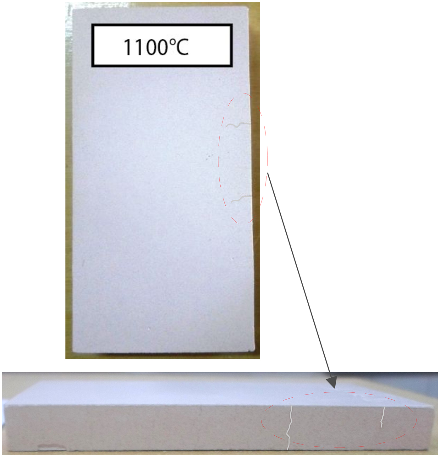
The behaviour of halloysite fired at 1100°C displays a high flexural strength (16.3 MPa) associated with shrinkage of 7.5%, indicating partial melting and development of vitreous phases. However, this change involved crack development (Fig. 8) due to the absence of quartz filler (Souza et al., Reference Souza, Messer and Lee2006). Flexural strength is mainly influenced by the development of mullite and the formation of a vitreous phase which probably improves the mechanical strength. Two crystal forms of mullite, related to feldspar and its interactions with halloysite, are recognized from examination of the microstructure at 1100°C shown by SEM. In general, mullite crystals grow in a viscous aluminosilicate liquid, as primary mullite in pure clays and secondary mullite in the presence of alkali fluxes (Na2O + K2O) (Lee et al., Reference Lee, Souza, McConville, Tarvornpanich and Iqbal2008), in agreement with chemical and mineralogical results obtained from the halloysite sample. However, other variables influence mullite formation by affecting the composition and viscosity of the liquid. At present it is difficult to determine the stoichiometry of mullite formed in vitreous systems due to the heterogeneous microstructure.

Fig. 8. Aspect of the halloysite fired product at 1100°C showing some deep cracking features.
In light of the result obtained, the halloysite studied is suitable for use as slightly vitrified raw materials for ceramics from 900°C, but appropriate formulations need to be designed to prevent manufacturing faults.
SUMMARY AND CONCLUSIONS
A Neogene halloysite deposit from the Nador region of Morocco, located at the foot of the Gourougou volcano in the Maazza Valley, has been investigated. A 25–130 cm thick wedge-shaped white layer of halloysite occurs in contact with lower reef limestone and upper volcanic sand. The clayey material consists of fine particles (68%), and has a high plasticity index (31.5%) and a fairly large specific surface area (55.5 m2/g). The deposit consists of 7 Å non-hydrated halloysite, gibbsite, alunite, K-feldspar, minor tridymite, fluorite and halite and traces of smectite and illite. The clay has a large Al2O3 content linked to the presence of some aluminous phases (gibbsite and alunite), which reduces slightly the SiO2/Al2O3 ratio.
Test specimens prepared and fired from 500 to 1100°C were used to evaluate the processing technique in ceramic products formed from raw halloysite material. An increase in linear shrinkage with great flexural strength was observed. Based on these results, the Moroccan halloysite might be used in the ceramics industry. However, addition of quartz sand would be necessary to avoid crack development at firing as well as to reduce the highly plastic behaviour of halloysite and minimize its shrinkage during sintering.