Published online by Cambridge University Press: 07 June 2005
This paper summarizes experimental results on the injection and transport of intense, wide cross-section H+ plasma (PB), and ion beams (IB), in vacuum and ambient H+ plasma across an applied B-field. The injection of plasma and ion beams into magnetic confinement devices have the potential to heat and support current in these systems (e.g., field-reversed configurations). The translational energies of the PB and IB ranged between Epb = 60 to 120 eV and EIB = 60 to 120 keV, with temperatures and densities in the range of Tb ∼ 2 to 10 eV, nb ∼ 1012 to 1013 cm−3, and Tb ∼ 200 eV, nb 1010 to 1011 cm−3, respectively. Compared to earlier studies (Peter et al., 1979; Wessel et al., 1988, 1990), this research extends the experimental parameter space to higher beam current densities (up to 30 A/cm2) and higher B-field strengths up to 1.6 kG. The PB and IB were both about 10 cm in diameter at the injection port, and the ratio of beam specific energy to ambient B-field specific energy, β, was in the range of 0.1 to 10. Ratios of beam Larmor radius to beam size, ρ, ranged from 10−1 to 1 and 1 to 10 for the PB and IB, respectively. Cross B-field propagation of the PB in vacuum was undeflected as a whole with a sharp increase (one order or more) in the current density of the central beam core at B-field levels > 1 kG accompanied by a significant loss of beam peripheral layers, beam “braking” and preferential beam expansion along the B-field lines. Cross B-field propagation of the PB in ambient plasma did not differ substantially from the case without B-field, that is, no deflection of the PB as a whole, which could be due to an insufficient neutralization of the induced E-field inside the PB. Cross B-field propagation of the IB in ambient plasma followed a single particle trajectory deflection with a simultaneous significant loss of IB intensity without any detectable bunching, indicating an adequate shorting of the polarization E-field inside the IB.
The following appear promising for various applications requiring propagation across magnetic field to a stand-off target and/or captured in ambient magnetized plasma: microsecond duration, intense neutralized ion (IB), and plasma beams (PB) with ion energies in the range of EIB ∼ 0.1 MeV and EPB ∼ 100 eV, and ion current densities of j ∼1 to 30 A/cm2 and j ∼10 to 100 A/cm2 for IB and PB, respectively. Numerous experimental and theoretical research with IBs and PBs generated in plasma Hall type accelerators (Morozov, 1974), high current ion accelerators (Bystritskii & Didenko, 1989), plasma thrusters (Dailey, 1965), laser produced plasma flows (Rai et al., 2003), and laser guided plasma channels (Niemann et al., 2003), have addressed the mechanisms of beam across B-field propagation in a vacuum and ambient plasma with respect to beam parameters (density, energy, temperature, size) (Peter et al., 1979; Song, 1990). Qualitatively, the propagation of PBs/IBs across B-field and the dynamics of B-field penetration into the beams depend on the value of β, which represents the ratio of the beam specific kinetic energy to B-field energy density. More specifically, the picture of beam propagation across B-filed can be roughly divided into three different modes, summarized as follows:
The requisite conditions for the collective mode of propagation across B-field, compiled from the previous studies which are of interest for the present study, are listed below:


Here, B is the applied B-field; nb is the beam density; β = v/c is relative beam translational velocity; nbEb is the specific translational energy of the beam ions; nbTb is the specific thermal energy of the beam; kB is Boltzmann's constant; Rb is the beam radius; RL is the Larmor ion radius; (mi/me) is the ion to electron mass ratio; δ is the polarized sheath thickness; LB is the length of beam transport and ε is the beam dielectric constant equal to 1 + (ωi/ΩL)2, where ωi and ΩL are the plasma and ion cyclotron frequencies.
Condition (1) is derived from the requirement that the energy density of the induced E-field in a beam traversing a B-field cannot be larger than the translational energy density of the beam, which can be written as E2/8π << nbmv2/2. Conditions (2a and 2b) account for the requirement of fast magnetization of the beam, when the ExE pressure is much larger than the translation energy density of the beam. Condition (2a) is applicable for the PB with a translational energy of the same order as its temperature (kBTb ∼ Eb), while condition (2b) is applicable for the IB, with a thermodynamic pressure a few orders less than its translational energy (kBTb << Eb). In the other limits, where B2/8π < nbEb and B2/8π < nbkBTb, strong diamagnetism during beam propagation can be expected. Condition (3) defines the magnitude of the polarized sheath thickness; δ, which must be much smaller than the size of the beam, Rb. Condition (4) was derived from the requirement that the full induced electric potential across the beam must be less than the translational energy of the ions. One-dimensional (1D) analysis (Peter et al., 1979) predicts the splitting of the beam into several beamlets if condition (4) is not met. Condition (5) defines the length of the virtual anode formation, LVA, which can impede the propagation of the beam and is based on a 1D estimation of LVA ∼ vb/(ΩiΩe)1/2. Condition (6), which is in fact equivalent to condition (1), requires the scale length formation of the polarized sheath, δ, to be much less than the LVA (Wessel et al., 1990). It is worth noting that, in the real two-dimensional (2D) geometry of the beam, a considerable decrease in the axial induced E-field occurs due to its partial shorting, by the accompanying beam electrons and subsequently the ions are able to propagate much farther than in the 1D estimation. In reality, the existence of an adequate neutralizing source of electrons along the B-field lines in experiments (i.e., conducting walls, ambient plasmas, etc.) alleviates this concern. The above general conditions can be combined and rewritten using the relations: Eb = nbeδ/ε0 and nb = j/eβc, in more practical forms providing a range for the desired beam parameters corresponding to the ExB mode of beam propagation across B-field:
Combining conditions 1 and 2:

results:

Combining conditions 2 and 5:

results:

Combining conditions 3 and 4:

results:

Here, for the sake of simplicity we substituted the symbol of strong inequality (>>) by (>) with an additional factor of 10. In our experiments, we studied ion and plasma beams which differed by three orders of magnitude in energy, two orders in density, and one order in pulse duration (102 keV, 1011 cm−3, 1 μs, and 0.1 keV, 1013 cm−3, 20 μs, respectively). Such a wide range of IB and PB parameters provided us with an opportunity to test the experimental applicability of the above criteria at higher levels of current density and B-field than was done in earlier experiments (Song, 1990).
This paper consists of five sections. In section 2, we briefly characterize the experimental setup including plasma sources for the generation of IBs and PBs and their respective parameters and diagnostics. Section 3 is dedicated to experiments on PB cross B-field injection and results. Section 4 discusses experiments on IB injection and results. Section 5 is dedicated to analysis and conclusion.
The schematic of the experimental setup is given in Figure 1. The system consisted of: (1) A vacuum vessel with ports located in the middle of the vessel length; (2) Plasma or ion beam accelerator, connected to the middle port of the vacuum vessel with beam injection normal to vessel axis 25 cm below vessel median plane; (3) Two sets of internal plasma guns which generated an ambient plasma column injected along the B-field; (4) Power drivers for ambient plasma guns; and (5) External solenoid coil for generating pulsed longitudinal B-field. The vacuum in the vessel was 4 × 10⁻⁶ to 10−5 Torr. The main operational parameters of the subsystems are given in Table 1.
Operational parameters of the subsystems


Schematic of the experimental setup: (1) Plasma guns power supply, (2) Set of plasma guns, (3) ExB coil, (4) PA/IA, (5) Coaxial vacuum vessel walls, (6) Ion beam and (7) Plasma column.
The ion accelerator produced a 1.5 to 2 kA, 70 to 120 kV, 0.5 to 1 μs H+ beam < 10 cm in diameter at the entrance port to the vessel with an average divergence half angle of 3°. The IB estimated ion temperature was TIB ∼ 200 eV which was based on the size and shape of ion beamlet autographs on heat sensitive paper obtained by using multi-aperture pinholes placed at the exit of the ion accelerator. The average density of IB was in the range of 1011 to 1012 cm−3. It has already been established by a variety of experiments that high current IB are almost completely charged neutralized (> 99%) at the exit from the accelerator, by the accompanying electrons being dragged in the IB by the self E-field of the IB from surrounding walls. The average velocity of the neutralizing electrons is of the same order as the ions (Humphries et al., 1976). In fact, such a high current IB could be considered for as synthesized non-equilibrium plasma of energetic ions with respect to electrons. The ion accelerator consisted of a: (1) 120 kV, 1 μs, 1.8 Ohm Marx generator; (2) magnetically-insulated ballistic-focusing diode (MID) with a magnetic coils system and a hydrogen puff valve located in the center of the anode; (3) a plasma source, based on a fast shock coil, which drives an inductive discharge in the expanding hydrogen flow; (4) a toroidal magnetic lens and a guiding solenoid for the focusing and transport of the IB to the entrance port of the vessel. The distance traveled by the IB to the vessel entrance from the MID was 90 cm and about 155 cm to the opposite wall of the vessel. For a more detailed description of the design and characteristics of the IB accelerator and ion beam parameters, we refer the reader to (Bystritskii & Didenko, 1989; Anderson et al., 2004).
The design of the plasma accelerator was based on the conventional Marshal gun with modifications based on earlier experiments (Morozov, 1974; Morozov et al., 2002) in an attempt to increase the plasma flow pulse duration. In most of the experiments, we used a squirrel cage type, coaxial, conical electrodes with and without additional radial plasma cable guns placed at the breach of the accelerating channel. The simplified schematic of the plasma accelerator is given in Figure 2. The plasma accelerator has an outer 27 cm long squirrel-cage-type conical electrode which is grounded at its 9.5 cm diameter base, and has a 3.7 cm diameter near the beam exit. The inner HV cathode is also a conical squirrel cage, however, is 23 cm long with a 2.5 cm diameter base.

Schematic of the plasma beam accelerator.
The plasma accelerator was driven with a HV pulse (10 μs, 3 to 9 kV, 80 to 140 kA) from a 150 μF capacitor bank and was switched by an ignitron. The hydrogen was delivered to the breach of the plasma accelerator by a fast electromagnetic puff valve with an opening time of < 80 μs and plenum pressure in the range of 100 to 400 kPa. The plasma accelerator worked in two modes: (1) with trigger-controlled application of the HV pulse to the cathode which followed the puff valve initiation to form snow-plow propagation of the formed plasma discharge; and (2) with DC application of HV to the cathode, resulting in the self breakdown deflagration mode of propagation (Cheng, 1990).
In the first mode, the gas breakdown in the plasma accelerator takes place near the breach of the accelerating channel (that is, near the insulating interface) and could be initiated near the high pressure branch of the Paschen pd-curve for pd > 10, (beyond minimum). These results in the snow-plow mode with a fast rising of the current through the plasma and its acceleration to the end of the cathode under the I × B force accompanied by a slanting of the current channel due to the Hall effect. Current slanting limits the initial pulse duration of the axial plasma acceleration to a few microseconds (the so-called anode current crisis when the accelerating force Ie × Bφ becomes radial and pushes the plasma flow from the outer anode to the axis), and consequently, reduces the final translational energy of the accelerated plasma (Morozov, 1974).
The typical ion signals of the accelerated plasma flow from the Faraday cups featured a two peak structure with a very short, a few μs duration, high amplitude first spike and ion average velocity in the range of ∼ 15 cm/μs (100 eV). The second peak occurred (a few tens of μs) after the first peak, and was lower in intensity with a > 20 μs pulse duration and velocity ranging between 106 to 107 cm/s.
To mitigate the influence of the current crisis and to extend the duration of the accelerated plasma, the plasma accelerator was modified by adding several (up to 4) cable plasma guns (see Fig. 2) near the insulator interface which fired radially inside the accelerator. Using this technique, we were able to obtain plasma ion pulses with durations of 40 to 50 μs, though with lower reproducibility and average plasma velocity. It is possible this could be due to the high concentration of carbon ions in the plasma generated by the cable guns, resulting in fast cooling of the hydrogen plasma flow from the plasma accelerator. Another possibility may be due to the limited reproducibility of the gas puff operation relative to the triggering of the cable guns. The CFC signals still featured a very short, high amplitude initial spike of a few μs in duration and an average ion velocity of ∼ 15 cm/μs (100 eV), however, with a less prominent two pulse structure than was seen without the additional cable guns.
In the deflagration mode, with the DC-voltage “sitting” on the inner electrode, the gas breakdown takes place automatically when reaching the pd-minimum of the Paschen curve at the front of the gas (Cheng, 1990). This results in the fast ionization and acceleration of the small front portion of the out flowing gas resulting in higher plasma velocities. When working in the deflagration mode, we did not succeed in extending its duration with the use of additional cable guns. The main experimental part of the data presented in this paper was taken for the snow plow mode with controlled triggering of the plasma accelerator.
The background plasma column was injected along the ExB from opposite sides of the vacuum vessel and was generated by two circular arrays of 16 TiH plasma guns (PG) of I × B type which were coaxial with the vessel axis and distributed uniformly along a circumference of 25 cm radius. The distance between two arrays could be varied from 0.8 to 1.3 m. The guns were driven in groups of four in parallel, by 20 μF capacitors charged between 7 to 13 kV with a total current of up to 100 kA per group producing a 10 μs FWHM pulse. Each capacitor was switched by a commercial ignitron with a rise time of ∼1 μs. The guns consisted of a titanium central electrode and outer washer electrode which were hydrogenated to the level of 1: 1, following the procedure outlined in Bystritskii et al. (1984). The PG schematic is given in Figure 3. The central Ti positive HV electrode was 5 cm long and 6.3 mm in diameter. The grounded coaxial Ti washer with a conical inner surface was placed at the exit from the PG forming a circular vacuum gap with the central electrode of 0.3 to 0.4 mm.

Schematic of the coaxial TiH plasma gun. (1) Stainless steel (SS) tube diameter 16 mm; (2) Polycarbonate insulator; (3) HV (6 to 10 kV) SS cathode stalk; (4) Ceramic disk; (5) TiH cathode; (6) TiH outer tube; and (7) Conical TiH washer.
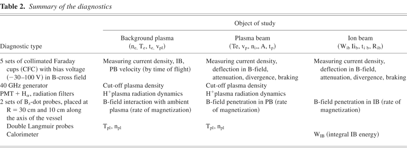
Measurements of the B-fields and the characteristic dynamics of the ambient plasma, PB, and IB were done with a variety of diagnostics which are listed in Table 2. Their respective locations are shown in Figure 4.
Summary of the diagnostics

Schematic diagnostic locations in the vessel (1) Double Langmuir Probe; (2), (5) Linear vertical CFC arrays; (3) Microwave source and receiver; (4), (6) Two BZ-dot arrays along the axis of the vessel; (7) Horizontal 900 bend CFC array; (8) Circular rotatable “shower head” CFC array; (9) PB/IB accelerator; (10) Transport solenoid; (11) Cable guns; (12) Horizontal CFC array.
The CFC had apertures of 7 × 10⁻³ to 4 × 10⁻² cm2, graphite electrodes of 3 mm in diameter, and were operated at bias voltages of −30 to −50 V and/or a transverse B-field of a few hundred Gauss. The ambient plasma density and speed of the plasma flow was recorded by two circular CFC arrays placed at a radius of 20 cm and opposite to each other in the plane of the PGs. Two Bz-dot probe arrays with 5 mm coil diameters were distributed along the axis of the vessel. One Bz-dot array was placed on the surface of the vessel's inner wall at a radius of ∼ 12 cm, while the other Bz-dot array was placed on the surface of the vessel's outer wall at a radius of ∼ 40 cm. The Bz-dot probes in both arrays were spaced at axial increments of 10 cm. The locations of these Bz-dot arrays provided us with the opportunity to map the topology of the B-field in time during PB and IB injection.
The temperature of the background plasma from the PG arrays was measured in several locations by a standard double Langmuir probe (LP) with tungsten tips, 1 mm in diameter, 1 cm in length, and 3.5 mm inter tip distance. The LP was energized, with controlled time delay, by pulse width duration of 200 ns. The current in the LP was registered by a commercial Pearson probe. The voltage between the probe tips was corrected for the inductive drop (LdI/dt) by the scheme shown in Figure 5.

Schematic of the double LP with voltage auto-correction.
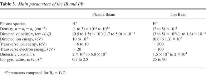
In the bulk of experiments with background plasma, the driver bank was charged between 7 to13 kV. The background plasma ion signal featured a familiar two pulse structure with the first pulse lasting a few microseconds and having a velocity ∼ 107 cm/s, and the second pulse lasting 10 to 20 μs with a velocity of 2 to 5 × 106 cm/s. 40 GHz microwave (μwave) measurements of background plasma density at a distance of 10 cm from the location of the TiH gun arrays, and 20 cm from the plane of the PB/IB injection, recorded a reliable signal cut-off, corresponding to a plasma density of n ∼ 3 × 1013 cm−3 (10 to 15 μs) after the background plasma arrays were fired. Each circular background plasma arrays of 16 guns produced an expanding tubular plasma layer with a divergence half angle of α ∼ 10° when fired without B-field and a thickness at the vessel mid-plane of ∼ 20 cm, as estimated by measurements from CFC array #2. With both background plasma arrays and axial B-field, the cut-off duration reached 100 μs and longer, depending on the charging voltage, and B-field strength. After a few hundred firings, there was a significant drop in the μ-wave cut-off duration which indicated a depletion of hydrogen in the TiH guns, and a need to replace the gun electrodes with re-hydrated pieces. The measurements of the background plasma temperature by the double LP, at the same position as the μ-wave horn, gave an average Te in the range of 5 to 10 eV, and average translational velocity (measured by CFC time-of-flight array) of a few 106 cm/s which could be slightly varied with driver voltages. The estimated full inventory of background plasma ion flow, based on this data, gives ∼ 1018 ions. Assuming energy of ∼100 eV is needed on average for the production of one H+ ion, the total energy input required for the background plasma volume formation is 0.8 kJ of the 8 kJ of total stored energy. Measurements of the plasma characteristics, when using cable guns as the background plasma source, gave lower reproducibility in the average data, higher initial translational velocity (up to 107 cm/s), and faster cooling (most likely due to carbon ion impurity). The ExB penetration rate in the background plasma was measured by an array of B-dot probes 10 to 15 μs after background plasma arrays were fired. This timing matched the plasma arrival at the mid-plane indicated by CFC arrays and the time needed for the density to buildup to cut-off level. The PB/IB injection was organized near this moment of time. The estimate of the classical conductivity of the background plasma, σ, based on the B-field penetration time delay τdif = 4πσL2/c2, gave ∼ 1013 (in CGS units). Here, L is the thickness of the plasma layer. This value is two orders lower than the Spitzer value based on double LP temperature measurements. This discrepancy could be due to other fast B-field penetration mechanisms such as whistler waves (Armal & Rostoker, 1996) produced by the Hall effect which help to “carry” the B-field in the plasma. An additional cause could be related to ion-neutral collisions, (especially with multi-electron impurities), resulting in the fast cooling of the plasma. The parameters of the ambient plasma and PB/IB are given in the Table 3.
Main parameters of the IB and PB
All experimental runs on beam propagation were done with a controlled triggering of the subsystems via computer. In testing the deflagration mode, the plasma accelerator fired ∼ 750 μs after the puff valve was energized, when the H2 pressure reached the required Paschen minimum for breakdown at the set voltage. In the snow plow mode, the optimal operation was obtained at a controlled HV application time delay of ∼ 800 μs after energizing the gas puff valve. Average jitter between plasma accelerator trigger and its actual firing was < 5 μs. The cause of this jitter was attributed to some mechanical inconsistency in the puff valve operation.
In the first part of the experiments, the exit of the plasma accelerator was located at 90 cm from the vessel mid-plane. In the second part, the exit was located 115 cm away from the mid-plane due to the addition of a beam expander and a 2.5 cm diameter collimator. The sequence of the subsystems operation and typical waveforms are illustrated in Figure 6.

The sequence of subsystems operations and respective typical pulse waveforms: (1) Applied B-field, (2) Background plasma gun current, (3) Plasma accelerator current, (4) PB current density.
As mentioned before, the typical plasma accelerator beam displayed a two-peak structure with translational energies in the range of 100 to 120 eV and 30 to 60 eV for the first and second peak, respectively. Time-of-flight measurements were taken between two positions of CFC arrays. When operating without the beam expander and additional diaphragm, linear CFC array #2 in the mid-plane (90 cm from the plasma accelerator anode) measured PB current densities between 30 to 60 A/cm2. This value dropped between 3 to 6 A/cm2 at 120 cm from the anode (near the opposite vessel wall). With the expander/collimator in place, the current density in the mid-plane ranged between 2 to 5 A/cm2 (∼ 115 cm from the plasma accelerator anode) and dropped below 2 A/cm2 near the opposite vessel wall (∼ 145 cm from the anode). Based on these numbers and the measured distributions of the IB current density at various locations, the estimated half angles of divergence of the PB at the entrance port to the vessel, at the mid-plane of the vessel, and at the opposite vessel wall were ∼ 10°, ∼ 14°, and ∼ 20°, respectively. Typical ion current density distributions measured by the CFC array #2 at the mid-plane of the vessel are illustrated in Figure 7a.

(a). PB current density distribution at the vessel mid-plane in vacuum without B-field. R- (vertical) radial distance of the CFC from PB injection axis. (b). PB current density distribution at the vessel mid-plane in ambient plasma w/o B-field. R- (vertical) radial distance of the CFC from PB injection axis.
Studies of the PB propagation in background plasma were performed with the collimated PB only. It was found that the addition of the expander/collimator deteriorated beam transport efficiency. The current densities for PB transport in ambient plasma were nearly identical, if not worse, to the vacuum case (∼ 5 A/cm2 and ∼ 2 A/cm2 at the mid-plane and opposite vessel wall, respectively). Several tentative causes why the transport efficiency did not increase with background plasma could be: (a) high initial angular divergence of the PB at the injection port; (b) ion-ion/neutral scattering; (c) background plasma-PB instabilities (they have comparable density); and (d) the influence of the residual self B-fields in the PB from plasma accelerator current loops. In the case of vacuum propagation, these current loops may have provided some self-focusing which would be absent in the case of PB injection into a current neutralizing background plasma. The typical current density distribution in the vessel mid-plane across the PB width for propagation in the background plasma can bee seen in Figure 7b.
The main results can be stated as follows:

(a) Typical current density distributions across PB vertical cross section in vacuum at vessel mid-plane for B-field strengths: 0.3 kG (left), 0.8 kG (middle), and 1.2 kG (right). R- (vertical) radial distance of the CFC from PB injection axis. (b) Typical current density distributions across vertical cross section of PB in magnetized plasma at the vessel mid-plane for B-field: 0.3 kG (left), 0.8 kG (middle), and 1.0 kG (right). R- (vertical) radial distance of the CFC from PB injection axis.
These experiments were done with a variable time delay (10 to 30 μs) between firing the background plasma gun arrays along the B-field and cross-injection of the collimated PB. The estimated ambient plasma density measured by μ-wave cut-off was on the level of ∼ 1013 cm−3. Compared with PB propagation in the background plasma without B-field, there was an expected overall drop in the density of the transported beam, assuming an adequate shorting of the induced E-field by the background plasma and respective bending of the PB. This said, the PB did not display any evident bulk deflection “up,” defined by the direction of the ExB, when measured by the CFC array # 8 at distances from the entrance port comparable with RL, (RL = 15 cm at B = 0.1 kG, for EPB = 100 eV). In some experiments, the distribution of the current density across the PB could be interpreted as some deflection (few cm) in the “down” direction. A possible cause for the absence of a clear deflection could be due to low ambient plasma density, nBP, with respect to plasma beam density nb (nBP < nb). In other words, the ambient plasma was insufficient to provide reliable shorting of the induced E-field in the PB. Another possible cause may have been the wide PB splitting into several beamlets. See Figure 8a for a PB current density distribution as a function of applied B-field in magnetized plasma.
The main part of the experiments with IB was done using an additional solenoid section of 60 cm length to increase the efficiency of the beam transport from the MID to the vessel entrance port. We also used two additional plasma cable guns in the space between the exit of the MID and entrance to the transport solenoid for local neutralization of the IB. The effectiveness of this approach is illustrated in Figures 9a and 9b. The IB was injected through the same port as the PB was attached to, located 25 cm lower than the equatorial plane of the vessel.

(a) IB current density distribution at the mid-plane in vacuum and without transverse B-field. R– (vertical) radial distance of the CFC from the IB injection axis. (b) IB current density distribution at the mid-plane with background plasma and w/o transverse B-field. R– (vertical) radial distance of the CFC from the IB injection axis.
The IB as a whole showed very small, if any, deflection from the axis of beam injection when propagating across B-fields in the range of 0.1 to 1.5 kG, as was expected according to the picture of ExB propagation. At the same time, its transport across the B-field was characterized by a strong attenuation of the IB current density across the beam width, including its core, in contrast to the case of central core bunching of the PB when transporting in similar conditions. At injection energy of 60 to 100 keV, the IB current density without B-field was 15 to 20 A/cm2 at the injection port and dropped to ∼ 1.5 A/cm2 at the mid-plane. With B-fields of 0.3, 0.8, and 1.2 kG, current densities at the mid-plane dropped further to ∼1, 0.75, and ∼0.5 A/cm2, respectively. These CFC measurements were done with linear CFC array #2 and are shown in Figures 10a to 10c.

(a) IB current density distributions near mid-plane with transverse B-field. R– (vertical) radial distance of the CFCs from the IB injection port axis. (b) IB current density distributions near mid-plane with transverse B-field. R– (horizontal) radial distance of the CFCs from the IB injection port axis. (c) Current density distributions of IB in vacuum at vessel mid-plane with transverse B-field of 0.3 kG (left), 0.8 kG (middle), and 1.2 kG (right). R– (vertical) radial distance of the CFCs from the IB injection axis. (d) Current density distributions across vertical cross section of the IB in magnetized plasma at vessel mid-plane for B-field strengths: 0.3 kG (left), 0.8 kG (middle) and 1.2 kG (right). R- (vertical) radial distance of the CFC from the IB injection axis.
Unlike PB, IB when injected into magnetized plasma, displayed a single particle type behavior, and followed a classical trajectory defined by the Lorenz force. Therefore, the IB propagation length, in general, was limited by the distance of < RL. This type of propagation is also accompanied by a very strong “bleeding” off (that is to say, attenuation), across the entire width of the IB. The IB current density profiles across the beam width for different B-field values at the mid-plane of the vessel are illustrated in Figure 10d. For a clearer picture of IB bending, which corresponds to the average velocity of the main portion of the IB, see Figures 11a and 11b for the ∼ 60 keV and the ∼ 120 keV IB, respectively.
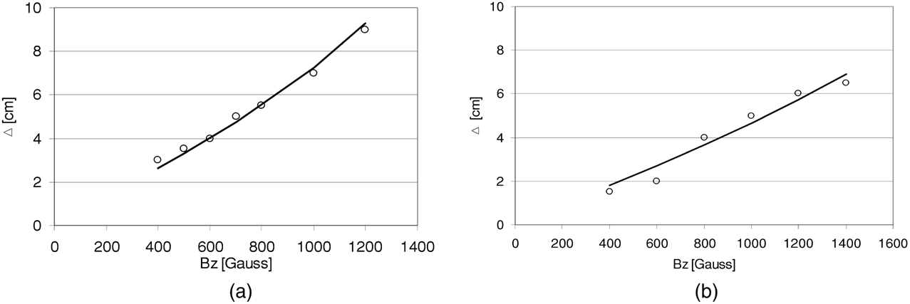
Radial shift of the current density “center of mass” with respect to the axis of the IB injection as function of the transverse B-field strength. Circles—experiment, line—calculation for ∼ 60 and ∼ 120 keV IB, respectively.
Comparison of the experimental beam parameters with calculations based on criteria 1 through 3 is given in Table 4. As seen from criterion #3, the transverse size of the experimental PB is far from the estimated range, which indicates a possible splitting of the beam into several beamlets. Another feature of PB propagation could be the formation of the virtual anode (Peter et al., 1979) as the beam enters the B-field region at the injection port. If the density nears the estimated limit, following criterion #1, a resulting partial reflection and/or enhanced expansion of the PB may occur.
Comparison of the experimental beam parameters with calculated based on the criterions 1–3

The results that deflection of the IB in magnetized plasma follows a one particle trajectory and that the efficiency of IB propagation in ambient plasma does not improve, but worsens compared to cross B-field IB propagation in vacuum, support the picture of efficient neutralization of the polarization E-field and enhanced scattering of the IB due to beam-plasma instabilities. Indeed, in the simplified condition for the onset of plasma-beam instabilities, vb > (nBP/nb)1/3〈vb〉, was easily fulfilled in our experiment (J. Huba, 2000, private communication). Here, <vb> is the thermal velocity of the beam ions (1 to 3 × 107 cm/s), vb is the translational velocity of the beam (3 to 5 × 108 cm/s) and (nBP/nb)1/3 was ∼ 3 to 4 in this experiment. Respective growth rates and frequencies of said instability, results in trapping (that is to say, braking) of the accompanying IB fast electrons, were in the range of (0.1 to 1)ωe or 108 to 109s−1. Here, ωe is the electron plasma frequency. Another candidate for the “pumping up” of beam-plasma instabilities in case of “hot” plasma electrons requires the fulfilling of the condition 〈vBP〉 > vb.> 〈vb〉, which was marginally satisfied in our experiment.
In general, the cause for the undeflected propagation of the wide PB in the magnetized plasma was credited to the background plasma density being insufficient to provide effective shorting of the polarization E-field. The above conditions for the on-set of fast instabilities, as in the case of IB propagation, are not fulfilled for the PB. Rather, slow instabilities of the ion trapping type (such as modified two stream, and/or ion-ion interactions), were deemed responsible for the enhanced scattering and broadening of the PB. Additional experiments are needed to elucidate exactly which mechanisms are dominating in both cases.
Comparing the experimental results with the expected results based on the criteria formulated in Section 1, we can make the following conclusions about the main features of the PB and IB behavior when propagating in vacuum and plasma across a B-field:
The authors would like to acknowledge stimulating discussions with Drs. S. Dettrick, W. Heidbrink, A Qerushi, F. Wessel, and the technical help of laboratory staff: S. Armstrong, M. Morehouse, K. Walters, and G. Strashnoy. This work was supported by The Tri Alpha Energy, Inc. and The University of California, Irvine.
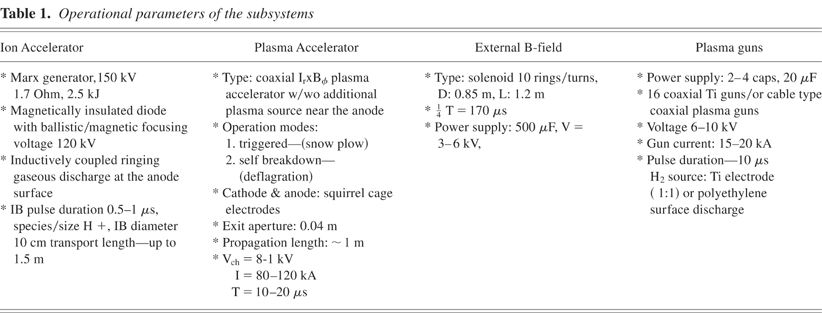
Operational parameters of the subsystems

Schematic of the experimental setup: (1) Plasma guns power supply, (2) Set of plasma guns, (3) ExB coil, (4) PA/IA, (5) Coaxial vacuum vessel walls, (6) Ion beam and (7) Plasma column.

Schematic of the plasma beam accelerator.

Schematic of the coaxial TiH plasma gun. (1) Stainless steel (SS) tube diameter 16 mm; (2) Polycarbonate insulator; (3) HV (6 to 10 kV) SS cathode stalk; (4) Ceramic disk; (5) TiH cathode; (6) TiH outer tube; and (7) Conical TiH washer.
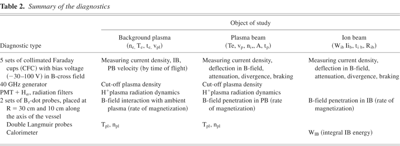
Summary of the diagnostics

Schematic diagnostic locations in the vessel (1) Double Langmuir Probe; (2), (5) Linear vertical CFC arrays; (3) Microwave source and receiver; (4), (6) Two BZ-dot arrays along the axis of the vessel; (7) Horizontal 900 bend CFC array; (8) Circular rotatable “shower head” CFC array; (9) PB/IB accelerator; (10) Transport solenoid; (11) Cable guns; (12) Horizontal CFC array.

Schematic of the double LP with voltage auto-correction.
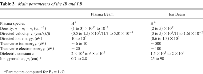
Main parameters of the IB and PB

The sequence of subsystems operations and respective typical pulse waveforms: (1) Applied B-field, (2) Background plasma gun current, (3) Plasma accelerator current, (4) PB current density.

(a). PB current density distribution at the vessel mid-plane in vacuum without B-field. R- (vertical) radial distance of the CFC from PB injection axis. (b). PB current density distribution at the vessel mid-plane in ambient plasma w/o B-field. R- (vertical) radial distance of the CFC from PB injection axis.

(a) Typical current density distributions across PB vertical cross section in vacuum at vessel mid-plane for B-field strengths: 0.3 kG (left), 0.8 kG (middle), and 1.2 kG (right). R- (vertical) radial distance of the CFC from PB injection axis. (b) Typical current density distributions across vertical cross section of PB in magnetized plasma at the vessel mid-plane for B-field: 0.3 kG (left), 0.8 kG (middle), and 1.0 kG (right). R- (vertical) radial distance of the CFC from PB injection axis.

(a) IB current density distribution at the mid-plane in vacuum and without transverse B-field. R– (vertical) radial distance of the CFC from the IB injection axis. (b) IB current density distribution at the mid-plane with background plasma and w/o transverse B-field. R– (vertical) radial distance of the CFC from the IB injection axis.

(a) IB current density distributions near mid-plane with transverse B-field. R– (vertical) radial distance of the CFCs from the IB injection port axis. (b) IB current density distributions near mid-plane with transverse B-field. R– (horizontal) radial distance of the CFCs from the IB injection port axis. (c) Current density distributions of IB in vacuum at vessel mid-plane with transverse B-field of 0.3 kG (left), 0.8 kG (middle), and 1.2 kG (right). R– (vertical) radial distance of the CFCs from the IB injection axis. (d) Current density distributions across vertical cross section of the IB in magnetized plasma at vessel mid-plane for B-field strengths: 0.3 kG (left), 0.8 kG (middle) and 1.2 kG (right). R- (vertical) radial distance of the CFC from the IB injection axis.
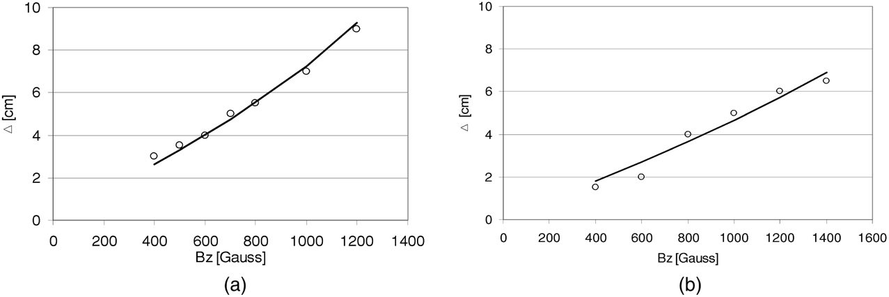
Radial shift of the current density “center of mass” with respect to the axis of the IB injection as function of the transverse B-field strength. Circles—experiment, line—calculation for ∼ 60 and ∼ 120 keV IB, respectively.

Comparison of the experimental beam parameters with calculated based on the criterions 1–3