Introduction
The fifth-generation (5G) communication technology has created many challenges in recent years for the design of mobile communication equipment, in particular the design of antennas [Reference Wu, Xia and Cao1, Reference Alsaif, Usman, Chughtai and Nasir2]. These challenges are all the more topical as market demand continues to expand. The need created by new applications in this field, imposes on operators a significant capacity in terms of bandwidth in their networks, a higher transmission rate, and a shorter latency than the current 4G system [Reference Berezdivin, Breinig and Topp3–Reference Zhang, Glazunov, Ying and He8]. In order to provide multimedia services in particular, these operators now offer multi-antenna systems with multiple frequency bands (multiple-input/multiple-output (MIMO) antenna systems).
Recently, many MIMO 5G antenna systems have been proposed [Reference Sun, Li, Zhang and Wang9–Reference Ojaroudi Parchin, Jahanbakhsh Basherlou, Al-Yasir, Abdulkhaleq and Abd-Alhameed23]. However, these designs only work for narrow-band operations (either single-band [Reference Sun, Li, Zhang and Wang9–Reference Parchin, Al-Yasir, Jahanbakhsh Basherlou, Abd-Alhameed and Noras13], dual-band [Reference Guo, Cui, Li and Sun14–Reference Li and Yang17], or triple-band [Reference Zhang, Li, Wang and Shen18, Reference Wang, Zhang, Luo and Yang19]). Very recently, the new radio containing the bands N77 (3.3–4.2 GHz), N78 (3.3–3.8 GHz), and N79 (4.4–5.0 GHz) and the new unlicensed radio containing the LTE46 band (5.15–5.925 GHz) have been recognized as essential components of the 5G spectrum below 6 GHz [Reference Zou, Li, Sim and Yang24–Reference Saxena, Kanaujia, Dwari, Kumar and Tiwari28]. However, each country will have the option of selecting its band from the three above. For example, the European Union (EU) had selected the N78 band; China had selected the N77 and N79 bands. It makes sense to work on a wide band that allows covering the whole band of the 5G spectrum. Some researchers have started working on this concept, such as Sim et al. [Reference Sim, Liu and Huang20] and Biswas et al. [Reference Biswas and Gupta21], however, they have not taken into account the initiatives launched by the Federal Communications Commission (FCC) to study the potential deployment of International Mobile Telecommunications (IMT) in the 5.9–7.1 GHz frequency band, considering making this band available for unlicensed operation. Cai et al. [Reference Cai, Li, Zhang and Shen22] and Ojaroudi et al. [Reference Ojaroudi Parchin, Jahanbakhsh Basherlou, Al-Yasir, Abdulkhaleq and Abd-Alhameed23] worked on these antennas as recommended by the FCC, they designed ring-slot MIMO ultra-wideband antennas dedicated to future smartphones. Ojaroudi et al. [Reference Ojaroudi Parchin, Jahanbakhsh Basherlou, Al-Yasir, Abdulkhaleq and Abd-Alhameed23] had designed an antenna of dimensions 34 × 34 × 1.6 mm3 composed of a circular slot radiator with open ends of outer and inner radii r 3 and r 2, fed differently by a pair of symmetrical microstrips in the shape of a semi-arched arc in an orthogonal line, the results of this topology gave good results in terms of radiation efficiency and envelope correlation coefficient (ECC) over a frequency band 2.5–10.2 (−6 dB). However, the proposed design has drawbacks in terms of insulation and antenna size. Cai et al. [Reference Cai, Li, Zhang and Shen22] have designed an antenna in the band 3.3–7.1 (−6 dB) using a narrow rectangular slot engraved on the ground and a space engraved on the side edge, could produce two modes, namely the inverted F antenna (IFA) mode and the slot mode, at the same time. The metallic side edge is directly powered by the microstrip feed line, so it could operate as a radiator (IFA section). By using a meander impedance transformer and an adapter, both modes can be moved and merged, thus allowing a wide bandwidth.
The design of the proposed antenna is inspired by leaky wave antennas [Reference Sghaier and Latrach29]. Due to the orthogonal arrangement of the feed lines, a function of polarization and diversity of the radiation pattern is provided [Reference Chandel and Gautam30–Reference Zhang, Zhao, Ying and He35]. In order to reduce the mutual coupling characteristic of the antenna ports, we have inserted a rectangular slot under each microstrip feed line [Reference Zou, Li, Sim and Yang24–Reference Saxena, Kanaujia, Dwari, Kumar and Tiwari28]. The reflection coefficients of the proposed antenna array are less than (−6 dB) in the 3.3–7.1 GHz band, with isolation >12 dB, radiation performance (radiation pattern, total efficiency, and realized gain) and MIMO performance (ECC and channel capacity (CC)) are also studied. The measured results of this study are compared with previous study, in order to highlight the novelty of the proposed antenna. CST microwave studio software is used to obtain the simulated results. This paper is organized as follows: Section ‘Dual-polarized wideband slot antenna’ highlights the geometry and design characteristics of a dual-polarized wideband slot antenna. The simulation and measured results of the proposed MIMO 5G antennas are presented in Section ‘Wideband MIMO antenna design for 5G smartphone’. In Section ‘Conclusion’, the characteristics of the smartphone antenna in proximity to the user are studied.
Dual-polarized wideband slot antenna
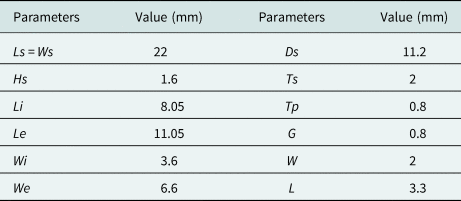
Figure 1 shows the geometry of the proposed antenna. A pair of symmetrical L-shaped microstrip lines in orthogonal positions are printed on the front side of an FR4 substrate of total dimensions Ws × Ls (22 mm × 22 mm) and (height hs of 1.6 mm, εr = 4.4, and tangential loss tan δ = 0.025), for feeding the antenna structure set to achieve an input impedance of 50 Ω. The antenna consists of a main radiator and two concentric annular slots, and they are etched on the back side of the substrate. Besides, we have coupled and linked the two rings by a small gap to combine and move the resonant modes so as to achieve wideband coverage. To reduce the mutual coupling characteristic of the antenna ports, a rectangular slot of (L × W) dimensions is inserted under each feed-line. Table 1 provides the dimensions of the proposed structure. The antenna is operating in the frequency range of 3.3–7.1 GHz. The impedance matching band of the proposed antenna is governed by several parameters, such as the dimensions of the slots and feed lines. All these parameters have been optimized to provide an operating frequency band with a mutual coupling of <10 dB.
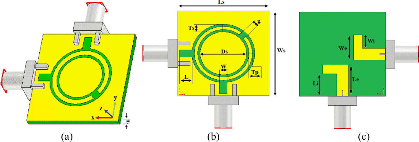
Fig. 1. Dual-polarized wideband slot antenna geometry: (a) transparent view, (b) back view, and (c) front view.
Table 1. Dimensions of the proposed structure

Figure 2 presents the iterations made to find the best compromise/solution for the design of the final antenna shape. Simulated S-parameters of the antenna design with a two concentric annular slots (Fig. 2(a)), without a rectangular slot (Fig. 2(b)), and the presented design (Fig. 2(c)) are shown in Figs 3(a)–3(c), respectively.
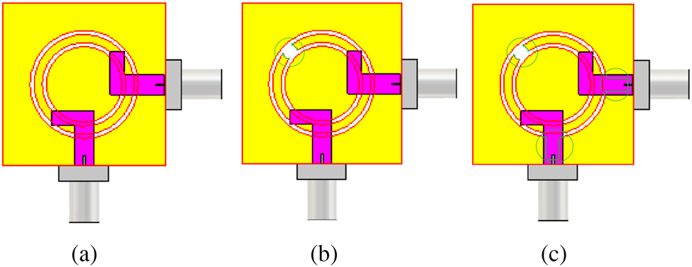
Fig. 2. Various configurations for the antenna design (a) with a two concentric annular slots, (b) without a rectangular slot, and (c) the proposed slot radiator.
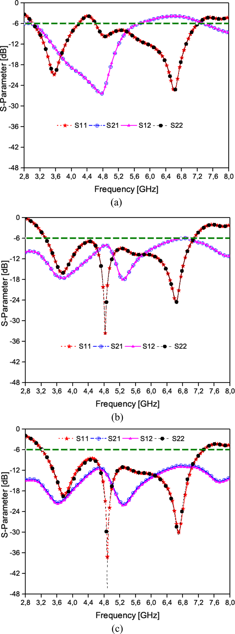
Fig. 3. Simulated S-parameter of Ant2a, Ant2b, and Ant2c.
As illustrated, the resonance frequencies of the antenna with two concentric annular slots are mainly fixed according to the length of the slots used. The first resonant frequency (3.5 GHz for the low band) depends mainly on the size of the outer slot (diameter, width, etc.). The second resonant frequency (6.5 GHz for the high band) is determined by the inner ring. Wideband coverage has been obtained after inserting a small gap between the two rings. Finally, by adding pairs of rectangular slot under each feed line, the antenna provides a good match with improved bandwidth and well-insulated characteristics at the desired frequency band (3.3–7.1 GHz).
In order to better understand the wideband characteristic, surface current densities of the Ant1 at 3.5, 4.5, 5.5, and 6.5 GHz are shown in Fig. 4.
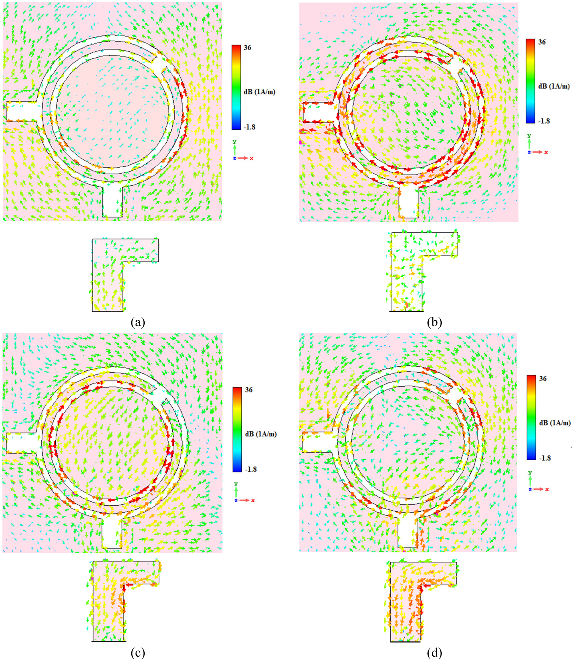
Fig. 4. Surface current distributions for the Ant1 at (a) 3.5 GHz, (b) 4.5 GHz, (c) 5.5 GHz, and (d) 6.5 GHz.
As shown in Fig. 4, the maximum surface current distributions were mainly concentrated around the slots created in the ground plane, because they are the main resonators of the design, which provides the different resonances of the antenna. The first resonance (at 3.5 GHz) is mainly determined by the circumference of the outer slot of the ring while the second resonance (at 5.5 GHz) depends on the inner ring. In addition, the current of the L-shaped microstrip feed-lines is very active at different frequencies. The aperture inserted between the two rings allows the improvement of the adaptation of the antenna and consequently the antenna becomes a wide band antenna but with poor insulation. At this stage, we thought of improving the insulation by using two notches under the feed.
The results of varying fundamental design parameters Ds, Tp, g, and Li are shown in Figs 5(a)–5(d).
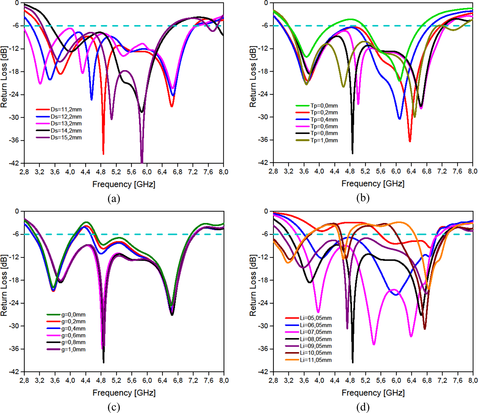
Fig. 5. Simulated return loss of antenna for different values (a) Ds, (b) Tp, (c) g, and (d) Li.
Figure 5(a) shows the effects of diameter Ds of two rings on the operating band under the following conditions: when the diameter increases from 11.2 to 13.2 mm, the frequency band increases and shifts toward the lower frequencies. However, for a diameter >13.2 mm the frequency band decreases. Figure 5(b) shows the variation of the return loss as a function of Tp which represents the thickness of the ring. Without a metal slot (which mean Tp = 0), the antenna has two resonant frequencies with poor adaptation. When the thickness increases from 0.2 to 1.0 mm with a step of 0.2 mm, the antenna's adaptation is improved and reaches its optimal values for a value of Tp equal to 0.8 mm. Therefore, it is clear that the addition of an adequate metallic ring leads to the creation of a wide band antenna and improves the adaptation of this antenna along the whole frequency range. Figure 5(c) shows the return loss characteristics for different values of g (gap width) by increasing the gap width, thus improving and increasing the bandwidth of the antenna. The length of the feed lines also has a very important effect on the adaptation and the width of the frequency band. For certain values of Li the antenna deviates multi-band as shown in Fig. 5(d). In this study, we have used the technique of inserting slots at the ground plane which generally allows us to miniaturize the size of the antennas: in fact it allows extending the path of the surface of currents and thus to decrease the resonant frequency of the antenna. It is even possible within a small area or dimension. The slots thus made on the antenna structure will also induce capacitive and inductive effects modifying the input impedance of the antennas. Moreover, the use of a slot not only allows the current paths to be extended but also the generation of new resonances. Afterward, the optimization of the dimensions and locations of the slots, the desired results are achieved.
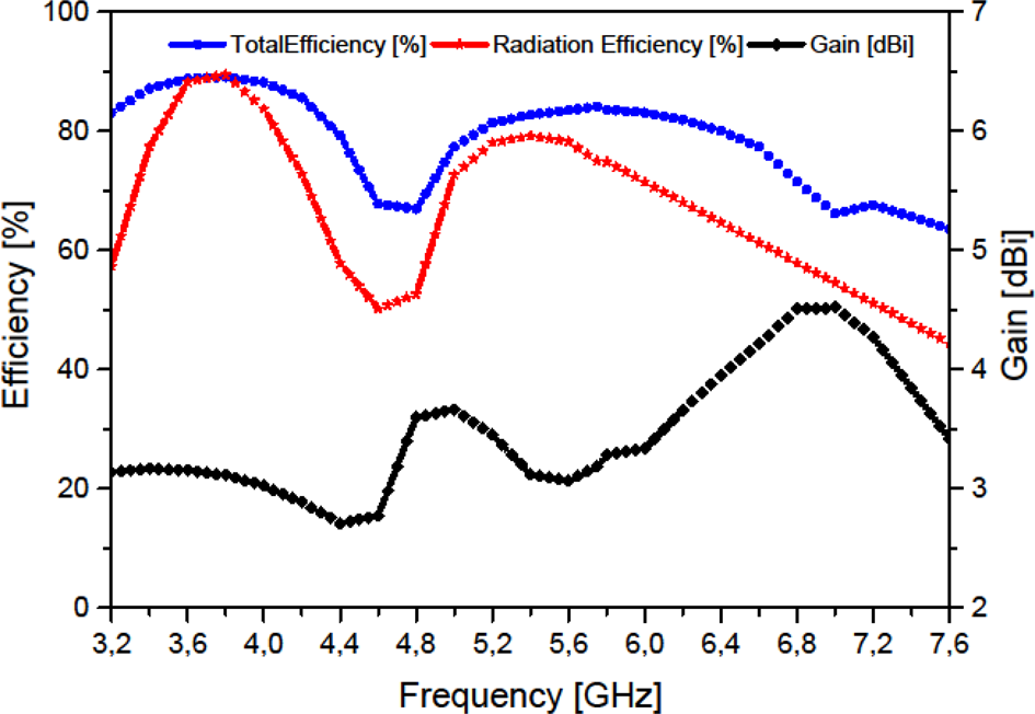
Figure 6 shows the radiation patterns of the antenna at resonant frequencies (3.5, 4.5, 5.5, and 6.5 GHz). As shown, the radiation patterns are omnidirectional. The maximum gain and efficiency of the antenna in the operating bands are shown in Fig. 7. More than 50% of the total efficiencies with maximum gains of more than 2.8 dBi have been achieved over the frequency band. In general, the antenna offers high efficiencies with sufficient maximum gain levels, even if it has been implemented on a high loss FR-4 dielectric.
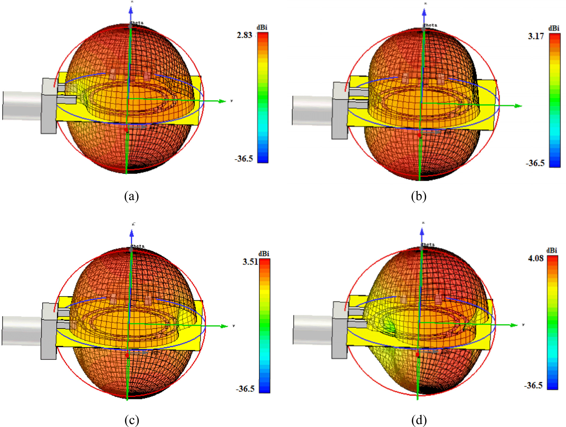
Fig. 6. 3D transparent views of the radiation patterns at (a) 3.5 GHz, (b) 4.5 GHz, (c) 5.5 GHz, and (d) 6.5 GHz.

Fig. 7. Maximum gain and efficiencies of the dual-polarized wideband slot antenna.
From the simulation results obtained in Fig. 3(a) of the starting structure of the antenna which is composed of two concentric rings (Fig. 2(a)), we have found that the antenna has generated two frequency bands. The first band is between 3.1 and 4.2 GHz and the second band is between 4.6 and 7.2 GHz. According to these results, the antenna is not adapted in the frequency range 4.2–4.6 GHz. By creating a gap between the two slots, we have improved the adaptation of the antenna which allows us to have a wide band antenna. However, it is necessary to emphasize that the values of S-parameter in the frequency range 4.2–4.6 GHz are very close to the limit value (−6 dB), as presented in Fig. 3(c), and this is what explains the cause of having the minimum values of gain and efficiency in this range (4.2–4.6 GHz as shown in Fig. 7).
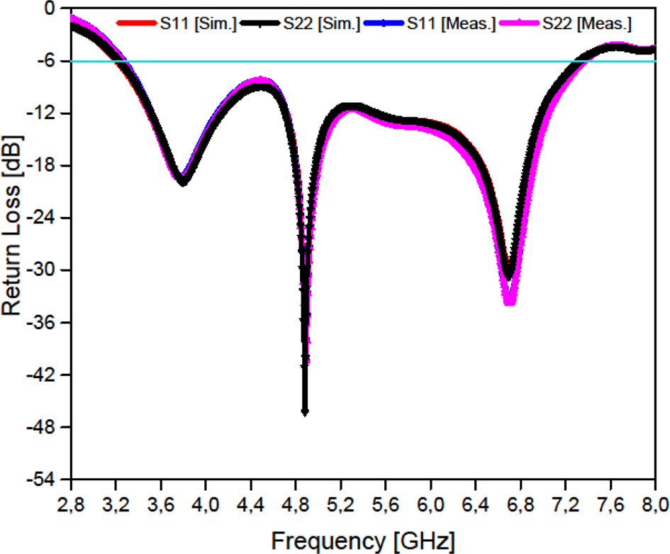
To appreciate the validity of the attained results, a prototype of the designed antenna is manufactured and measured. Photographs of the fabricated prototype and its simulated and measured reflection coefficients for the criteria (−6 dB) are shown in Figs 8 and 9, respectively.

Fig. 8. Fabricated antenna: (a) front view and (b) back view.

Fig. 9. Measured and simulated return losses of the dual-polarized wideband slot antenna.
The measured and simulated S-parameters of the design are compared and illustrated in Fig. 8. A good agreement between simulation and measurement results is achieved. It is seen from Fig. 9 that the antenna covers the band 3.3–7.1 GHz.
Wideband MIMO antenna design for 5G smartphones
S parameters
Figure 10 depicts the front and back views of the wideband MIMO antenna design. The design structure contains four pairs of compact microstrip-fed slot antennas, located at the corners of an FR-4 printed circuit board. The FR-4 substrate, with a height of hs = 1.6 mm, is used as a low-cost material with standard size dimensions of 150 × 75 mm2 for the smartphone mainboard. Each pair of antennas consists of a radiator with two concentric annular slots, fed by two L-shaped microstrip-feeding lines and provides polarization and radiation pattern diversity function due to the orthogonal placement of their feed-line.

Fig. 10. Wideband MIMO antenna design for 5G smartphone: (a) back view and (b) front view.
In order to compare the simulation results, we have manufactured the wideband MIMO antenna. The top and bottom views of the prototype are shown in Figs 11(a) and 11(b) respectively.
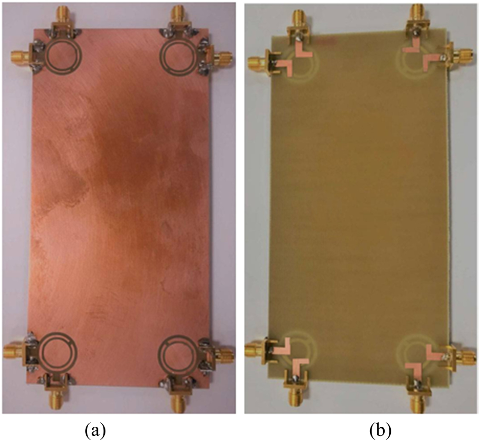
Fig. 11. Fabricated wideband MIMO antenna design for 5G smartphone: (a) back view and (b) front view.
Its properties in terms of S parameters, radiation patterns, and gain levels have been correctly measured. Figure 12(a) shows the simulated/measured S-parameters (S 11–S 88 and S 21–S 81) of diversity antenna radiators. It can be observed that at −6 dB each antenna element can completely cover the 3.3–7.1 GHz bandwidth. In Fig. 12(b), the isolation of a few typical antenna pairs is plotted. For the adjacent antennas (Ant1 and Ant2), the results show that the isolation is >12 dB.
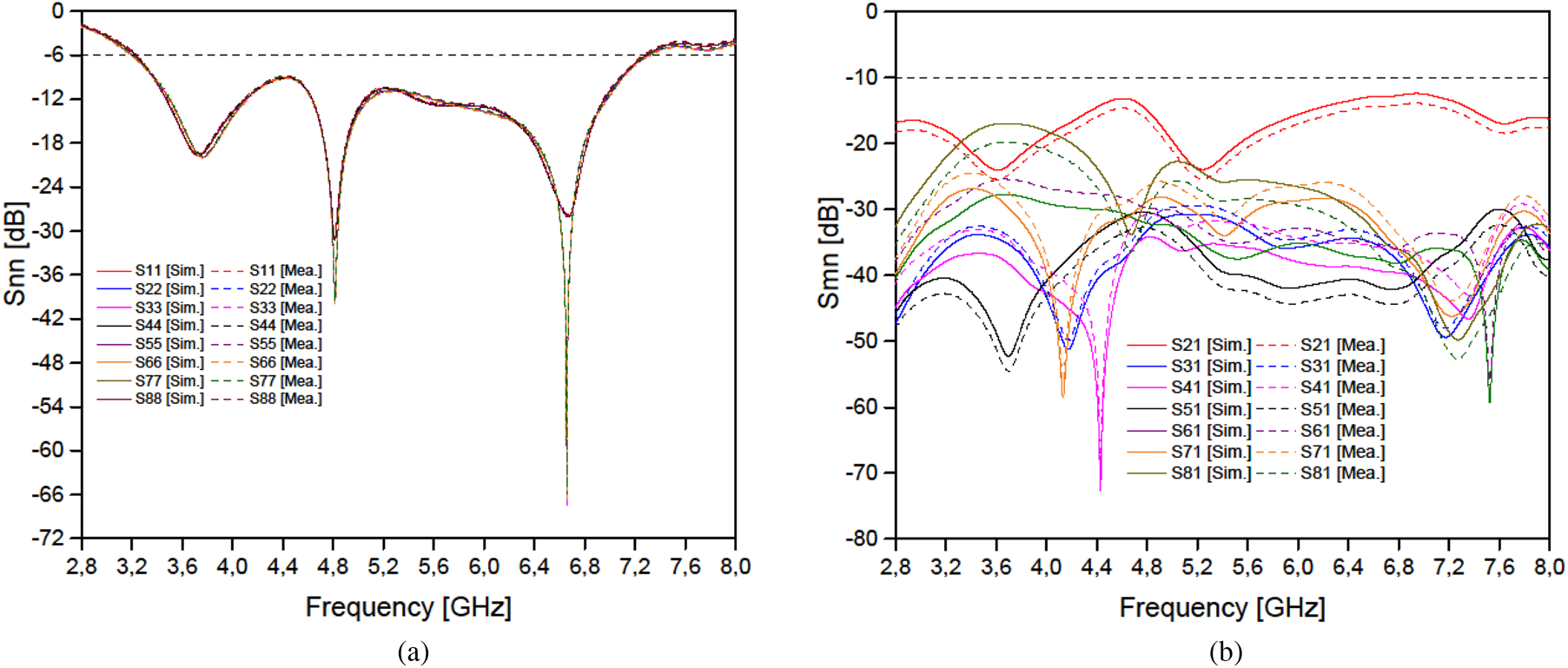
Fig. 12. Measured and simulated S parameter results: (a) Snn (S 11–S 88) and (b) Smn (S 21–S 81).
As soon as the separation distance between the antennas increases, the isolation increases. For example, if we take the case of Ant1 and Ant8, the isolation between them exceeds 18 dB. For other cases, the isolation exceeds 25 dB. It should be remembered that there is a good agreement between the simulated and measured results.
Radiation performance
The total measured and simulated antenna efficiencies and realized antenna gains are illustrated in Fig. 13. Note that we have selected the performances of Ant1 and Ant2; this is the most critical case due to the short separation distance between them. It can be seen in Fig. 13 that the measured total antenna efficiency and antenna gain agree well with the simulation. In the whole band 3.3–7.2 GHz, the total measured antenna efficiency is above 50%; and the measured and simulated antenna gains are in the range of 4.6–6.2 dBi. The above measured results confirm, once again, that the proposed wideband 8-antenna MIMO system has not only good isolation, but also good total antenna efficiency.
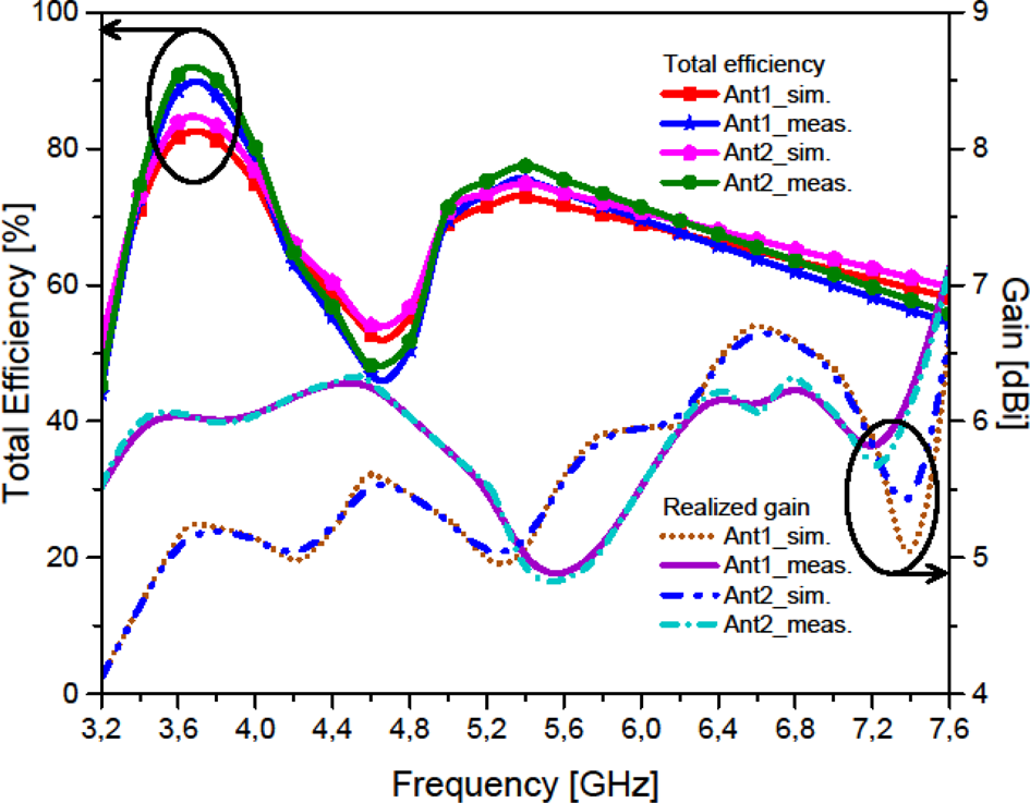
Fig. 13. Simulated (a) realized gain, (b) total efficiency of the proposed antenna array while holding a smartphone in one hand.
In addition, the two-dimensional radiation patterns of the manufactured antenna were measured. Figure 14 shows the measured/simulated radiation patterns of antennas 1 and 2 for the frequencies 3.5, 4.5, 5.5, and 6.5 GHz. In this design, the xz plane is the H plane (Ф = 0°) and the yz plane is the E plane (Ф = 90°) for the proposed antenna. In Fig. 15, it can be seen that the antenna can give dumbbell-shaped radiation characteristics in the E plane and almost unidirectional patterns in the H plane. It has been found that the radiation patterns of the wideband MIMO antenna deteriorate more or less with increasing frequency. However, the radiation properties are almost stable.

Fig. 14. Total efficiency and realized gain of Ant1 and Ant2.

Fig. 15. Simulated and measured in the E-plane (a) for Ant1 and (b) for Ant2 and in the H-plane (c) for Ant1 and (b) for Ant2 working at 3.5 GHz, 4.5 GHz, 5.5 GHz, and 6.5 GHz.
The three-dimensional (3D) radiation patterns of antennas 1 and 2 for the frequencies 3.5, 4.5, 5.5, and 6.5 GHz are plotted in Fig. 16. Observing Fig. 16, it can be seen that each side of the motherboard is covered with vertically and horizontally polarized radiation patterns. Thus, the smartphone antenna has good radiation coverage and the polarization diversity validates its potential for future smartphone applications.

Fig. 16. Simulated 3D patterns for the Ant1 and Ant2 at (a) 3.5 GHz, (b) 4.5 GHz, (c) 5.5 GHz, and (d) 6.5 GHz.
MIMO performance
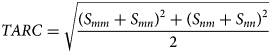
In order to evaluate the MIMO performance of the antenna proposed, ECC and Total Active Reflection Coefficient (TARC) are two important parameters to be studied. The ECC and TARC characteristics can be calculated from the complex measured and simulated results [Reference Shi, Zhang, Li, Jia, Chen and Zhang36–Reference Sun, Feng, Li and Zhang39] of each antenna element using the below equations:

Figures 17(a) and 17(b) show the calculated TARC and ECC. As illustrated in Fig. 17, the calculated TARC and ECC results are very low over the entire bandwidth. The ECC is <0.07 over the entire frequency band. This result proves that adjacent elements are not relevant. Furthermore, its TARC function is <12. Based on the results, the design is very suitable for MIMO applications. The design of MIMO antennas also requires the evaluation of the channel capacity loss (CCL). This parameter can be calculated as a function of S-parameters [Reference Shi, Zhang, Li, Jia, Chen and Zhang36–Reference Sun, Feng, Li and Zhang39] using the below formulas:


where


Fig. 17. Calculated MIMO performance of the antenna from measured and simulated S-parameters: (a) TARC and (b) ECC.
The last parameter to be studied to evaluate MIMO performance is the ergodic CC [Reference Khan, Al-Hadi and Soh38, Reference Sun, Feng, Li and Zhang39] which can be calculated by the following formulas:

where

Figure 18 depicts the loss of CC calculated from the measured and simulated results of the proposed wideband MIMO antenna. The maximum value of CCL in the band 3.3–7.1 GHz is around 0.28 bps/Hz, whereas the accepted limit value is 0.4 bps/Hz. However, the calculated CC over the entire operating band is about 40 bps/Hz, whereas in the ideal case it is about 46 bps/Hz [Reference Khan, Al-Hadi and Soh38, Reference Sun, Feng, Li and Zhang39]. From the calculated results of CCL and CC, it can be confirmed that the proposed wideband MIMO antenna has provided largely sufficient performance for mobile applications.

Fig. 18. Calculated MIMO performance of the antenna from measured and simulated S-parameters: (a) CCL and (b) CC.
Performance comparison
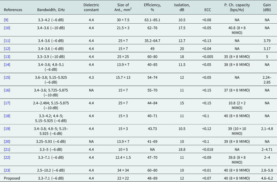
In this section, we will highlight the novelty of the proposed design. Table 2 compares our design with the current MIMO 5G smartphone antennas. The antennas proposed in [Reference Sun, Li, Zhang and Wang9–Reference Parchin, Al-Yasir, Jahanbakhsh Basherlou, Abd-Alhameed and Noras13] can only cover a single band of the 5th generation, with poor results in terms of efficiency and isolation except for the antenna design [Reference Chang, Yu, Wei and Wang12] which has a very acceptable isolation around 20. The antennas proposed in [Reference Guo, Cui, Li and Sun14–Reference Wang, Zhang, Luo and Yang19] are practically better than the designs described above as they allow to cover two bands and even three bands, however they cannot cover the unlicensed bands (LTE46/IMT) required by the FCC. For the same reasons, the studies [Reference Sim, Liu and Huang20, Reference Biswas and Gupta21] despite the fact that they could design a wideband antenna but are unsatisfactory as they did not meet the five bands required for 5G. The studies [Reference Cai, Li, Zhang and Shen22, Reference Ojaroudi Parchin, Jahanbakhsh Basherlou, Al-Yasir, Abdulkhaleq and Abd-Alhameed23] are practically much better placed than the previously mentioned antenna designs, as they could meet the FCC specifications. The antenna presented in [Reference Cai, Li, Zhang and Shen22] covers practically the same band studied in this paper but with a lower performance than the one achieved by our design in all aspects and especially in terms of gain, isolation, efficiency, and ECC. The antenna presented in [Reference Ojaroudi Parchin, Jahanbakhsh Basherlou, Al-Yasir, Abdulkhaleq and Abd-Alhameed23] has worked on a very wide band at 121%, however this concept presented a much larger size and lower performance compared to our antenna in terms of gain and isolation.
Table 2. Comprehensive comparison between the proposed study and other studies
Effects of users' hand
The effect of the hand on the performance of the proposed 8-antenna MIMO system will be studied. Figure 19 illustrates a typical case of a user holding a cell phone in one hand [Reference Elshirkasi, Abdullah Al-Hadi, Mansor, Khan and Soh40–Reference Hui, Jiang and Sailing42]. Referring to [Reference Certification43], the electrical properties of the hand phantom are modeled on the desired frequency band (from 2.8 to 6 GHz). These properties mainly depend on the frequency. The real part of permittivity ranges between 18 and 30 whereas the conductivity varies between 1 and 4.4 S/m. The return loss, isolation, gain, and total efficiency of the antenna are discussed in this section. The return loss and isolation of the proposed 8-antenna MIMO system with a phantom hand are shown in Figs 20(a) and 20(b), respectively. It can be seen in Fig. 20(a) that the return losses for all other antennas are well below −6 dB. And the results in Fig. 20(b) show that with the exception of S 12 which is above 15 dB in the whole frequency range, all other isolations are better than 15 dB. The results of the above S parameters certainly indicate that the proposed 8 × 8 antenna MIMO system works well when held by the hand of the phantom. On the other hand, the way in which the gain and the total efficiency of the antenna are influenced by the ghost's hand is also studied.
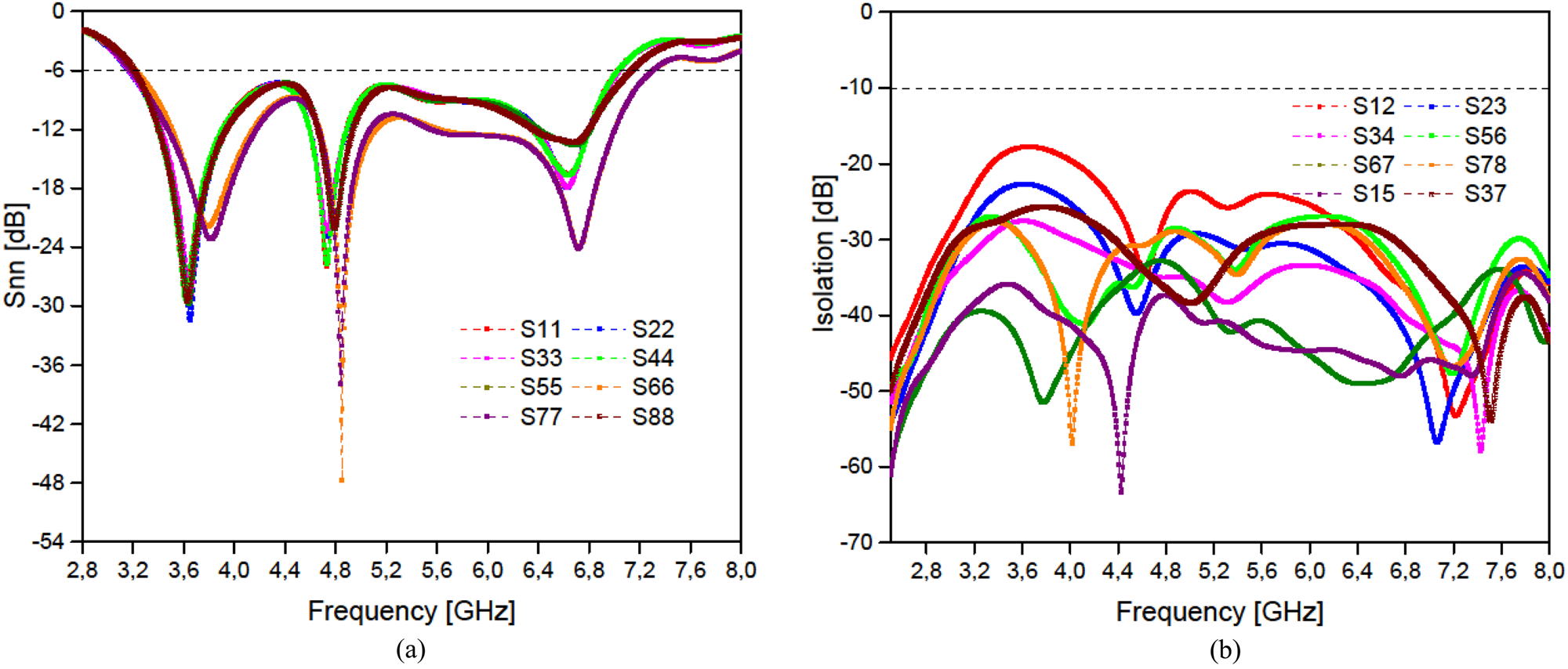
Fig. 19. Typical case of holding a smartphone in one hand.
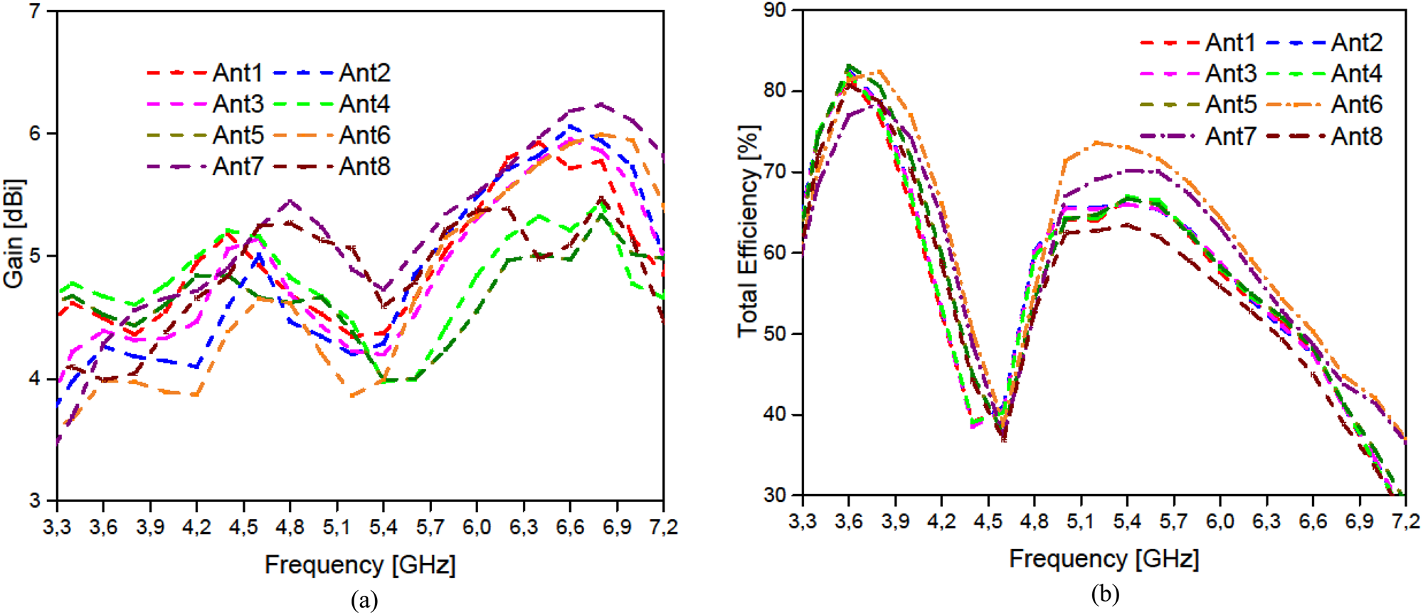
Fig. 20. Simulated (a) return loss, (b) isolation of the proposed antenna array while holding a smartphone in one hand.
Figures 13(a) and 13(b) show the gain and the total efficiencies of all the different antennas. Compared to the free space case, the gain and the total efficiency of the antenna decrease for the handheld case. In particular, the antenna with the most phantom manual coverage suffers a greater degradation of efficiency, as expected. However, it can be seen from the above results that when the proposed 8-antenna MIMO system is held by the phantom hand, its overall performance is still acceptable.
Conclusion
A new 8-antenna wideband MIMO array has been proposed for future 5G smartphones to cover the 3.3–7.1 GHz band. The design structure contains four pairs of compact microstrip-fed slot antennas, located at the corners of an FR-4 printed circuit board. Each pair of antennas consists of a radiator with two concentric annular slots, fed by two L-shaped microstrip-feeding lines and provides polarization and radiation pattern diversity function due to the orthogonal placement of their feed-line. In order to reduce the mutual coupling characteristic, we have inserted a rectangular slot under each microstrip feed-line. Besides, we have coupled and linked the two rings by a small gap to combine and move the resonant modes so as to achieve wideband coverage. Measured and simulated results show that the proposed design achieves the desired performance, such as an isolation >12 dB, a total efficiency >48%, and an ECC <0.07. In addition, the radiation pattern, the total efficiency, the realized gain, and the CC are also studied. According to the obtained results, the proposed MIMO antenna may be a suitable application-oriented design for 5G mobile communication.
Acknowledgement
We are especially thankful to Prof. Ali Gharsallah and all the members of the laboratory of the Faculty of Sciences of Tunis for the time and guidance given through this study.
 Nizar Sghaier received his Master's degree in Electrical Engineering: System Analysis and Digital Processing from the Faculty of Sciences of Tunis, Tunisia, in 2011. He received his Ph.D. degree in Electronics from the Faculty of Sciences of Tunis, Tunisia, in 2016. He is currently an Associate Professor in the University of SESAME and a Research and Development Manager in SKY, Tunisia.
 Lassaad Latrach received his Master's degree in Electrical Engineering: System Analysis and Digital Processing from the Faculty of Sciences of Tunis, Tunisia, in 2006. He received his Ph.D. degree in Electronics from the Faculty of Sciences of Tunis, Tunisia, in 2010. He received his Thesis Habilitation Degree in Electronics and Microelectronics from the Faculty of Sciences of Tunis, Tunisia, in 2016. He is currently an Associate Professor in the National School of Computer Sciences, Tunisia.