NOMENCLATURE
- θ m
-
flight-path angle
- θ f
-
expected impact angle
- μ
-
guidance coefficient
-
 ${\bm\omega }$
-
angular velocity of the LOS
- ψ V
-
heading angle
- λ
-
relative transverse component
- a
-
acceleration vector of the missile
- g
-
acceleration of gravity
- nx , ny , nz
-
missile overload along x-, y-, and z-axis
- q
-
line-of-sight angle
- r
-
relative position vector of the missile and target
- r
-
baseline length
-
 $\dot{r}$
-
change rate of the baseline length
- v
-
velocity scalar
- vm
-
velocity of missile
- v + m , v − m
-
upper and lower bounds of the missile velocity
- v + t , v − t
-
upper and lower bounds of the target velocity
- x
-
tangent unit vector of the curve
- x er
-
relative distance vector from the reference point to the target
- y
-
bi-normal unit vector of the curve
- z
-
normal unit vector of the curve
- u
-
curvature
- l
-
torsion
- APG
-
Augment Proportional Guidance Law
- BPG
-
Bias-Proportional Guidance Law
- LOS
-
Line-of-Sight
- MCPG
-
Motion Camouflage Proportional Guidance Law
- PG
-
Proportional Guidance Law
- VCPG
-
Variable Coefficient Proportional Guidance Law
- m
-
missile
- t
-
target
Abbreviations
Subscript
1.0 INTRODUCTION
The guidance law plays an important role in the terminal phase when the air-to-ground missile attacks the target. A feasible guidance law should not only achieve the required guidance precision but also satisfy the terminal impact-angle constraint. Obviously, the traditional homing guidance law is not qualified for this kind of mission. In 1973, Kim and Grider(Reference Kim and Grider1) first introduced the impact-angle constraint in the re-entry-guidance-law design problem, proposing a feasible guidance system with time-varying feedback gains by applying quadratic optimisation techniques. After that, a number of different guidance laws, considering the impact-angle constraint, were proposed by different theoretical approaches.
Proportional Guidance Law (PG) is widely used in the missile interception field for its simple form and implemented easily. Considering impact-angle constraint, proportional guidance law has been improved to different forms, including Bias-Proportional Guidance Law (BPG), Variable Coefficient Proportional Guidance Law (VCPG) and Augment Proportional Guidance Law (APG)(Reference Lee, Kim and Tahk2–Reference Ghosh, Ghose and Raha4). In Ref. Reference Lee, Kim and Tahk2, an interception-angle control guidance law was studied based on the traditional PG. In this method, the interception angle is estimated using the closed-form trajectory solution. And then, the difference between the estimated and expected angle is regarded as feedback information and introduced to the guidance commands. However, this guidance law is only available for the stationary ground target. To improve the overload characteristic when attacking moving targets, the VCPG is proposed. Reference Reference Ratnoo and Ghose3 gives an adaptive proportional guidance law that can switch the navigation coefficient. An adaptive adjustment function for the navigation coefficient is derived aiming at non-stationary non-manoeuvering targets, and the adaptive proportional guidance law with feedback is presented based on the missile model. The modified proportional guidance laws can deal with angle constraint, but it requires a time-to-go estimation and the velocity of the missile be constant.
The optimal guidance law is investigated intensively based on optimal control theory. According to the tactical and technical requirement of the missile, the performance index is introduced. Then, the explicit guidance equation is derived using the minimum principle based on the relative motion equation. Reference Reference Chen, Yu and Dong5 proposes a three-dimensional optimal guidance law with angle feedback for the reentry flight vehicle considering impact-angle constraint. The simulations based on stationary and slow-moving targets are conducted, respectively. And the attack precision and impact-angle constraint are met. In Ref. Reference Taub and Shima6, a closed-form sub-optimal guidance law based on trajectory shaping guidance scheme is designed. The missile has a time-varying acceleration bound and the dynamic characteristic of autopilot is taken into consideration. This law, using the linear quadratic optimal control theory, gives the time-varying gains which satisfy the constraints. To enhance the robustness, Lee et al(Reference Lee, Ryoo and Kim7) design an optimal guidance law that satisfies the impact-angle constraint as well as terminal-acceleration constraint. By ignoring the influence of the manoeuver acceleration at the impact instant, the command saturation is avoided and the robustness is enhanced.
In recent years, the finite-time convergence guidance law has been investigated intensively, which is based on the finite-time stability of the non-linear system(Reference Bhat and Bernstein8). Sun et al(Reference Sun, Zhou and Hou9) propose one kind of finite time convergence guidance law based on target-missile relative motion equations, considering the dynamics of a missile's autopilot as a first-order lag. The proposed guidance law proves that the states of the guidance system and the Line-of-Sight (LOS) angular rate converge to a sliding-mode and zero in finite time, respectively. To apply the finite-time convergence guidance law on the terminal-angle constraint problem, Refs Reference Yu, Xu and Zhi10 and Reference Zhang, Sun and Chen11 design the guidance law based on the sliding-mode control, and the convergence time is calculated using the finite time control theory. However, the negative exponent item in the guidance law will lead to singularity. Although the guidance laws based on the modern control theory show excellent performance, these guidance laws have a disadvantage that they need the second derivative of LOS or other information of the target.
Motion Camouflage (MC) theory was first proposed in 1995, Srinivasan and Davey(Reference Srinivasan and Davey12) explained the predatory strategy of insects with MC theory. This strategy can be simply described as in the process of the predator pursues the target, the predator camouflages itself against a fixed background object so that the prey observes no relative motion between the predator and the fixed object. Because of its significance in military application, this strategy has been used in spacecraft rendezvous, unmanned aerial vehicle flight path planning, and so on(Reference Xu and Basset13–Reference Basset, Xu and Pham15). Many scholars also have studied interception guidance. Mischiati and Krishnaprasad(Reference Mischiati and KrishnAprasad16) studied the dynamics of motion camouflage interception model and convergence issues. Bakolas and Tsiotras(Reference Bakolas and Tsiotras17) studied the robustness issues of motion camouflage guidance law under a two-dimensional flow field, and compared the performance of different guidance law. Gao et al(Reference Gao, Li and Jing18) designs an intercept guidance law based on motion camouflage strategy. The three-dimensional guidance law design problem is simplified as a two-dimensional problem and a two-dimensional guidance law for three-dimensional space is derived.
This paper proposes an adaptive guidance law for attacking ground target based on motion camouflage strategy considering the impact-angle constraint. First, the interception condition of the missile is derived from motion camouflage characteristics which is obtained by the theory of motion camouflage. Then, according to the interception condition, we derived the motion camouflage guidance law. To improve the acceleration characteristic of the initial homing phase, an adaptive feedback coefficient is introduced; thus, the adaptive guidance law is designed. Finally, based on the designed guidance law, the impact-angle constraint is considered and a corresponding adaptive guidance law is derived. Unlike many other guidance laws, the proposed approach doesn't require more information, such as the second derivative of LOS or the derivation of the acceleration. The efficacy of the proposed approach is demonstrated by the simulations of different examples.
2.0 DYNAMIC MODEL
The dynamic equation of the missile is as follows(Reference Babu, Sarma and Swamy19):
 $$\begin{equation}
\begin{array}{@{}l@{}} \displaystyle\frac{1}{g}\displaystyle\frac{{d{v_m}}}{{dt}} = {n_x} - \sin {\theta _m}\\[6pt] \displaystyle\frac{{{v_m}}}{g}\displaystyle\frac{{d{\theta _m}}}{{dt}} = {n_y} - \cos {\theta _m}\\[6pt]\quad - \displaystyle\frac{{{v_m}}}{g}\cos {\theta _m}\displaystyle\frac{{d{\psi _V}}}{{dt}} = {n_z} \end{array},
\end{equation}$$
where vm is the velocity of missile; θ m is the flight-path angle; ψ V is the heading angle; g is the acceleration of gravity, which is regarded as a constant, i.e., g = 9.8m/s2; ni (i = x, y, z) represents the projection of the missile overload on each coordinate axis, which is defined as a ratio of the external force to the weight of missile. In this paper, the guidance law gives out the value of ni (i = x, y, z) at each time. Tracking the overload commands, the missile can intercept the target successfully.
To design the overload command, the relative motion relationship between the missile and target needs to be established. Figure 1 shows the relationship in Frenet frame.
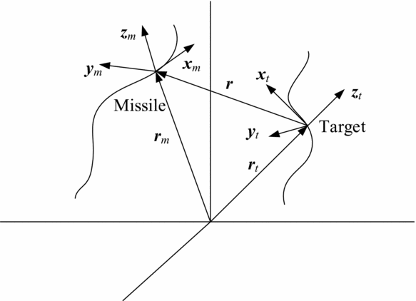
Figure 1. Missile-target engagement geometry in Frenet frame.
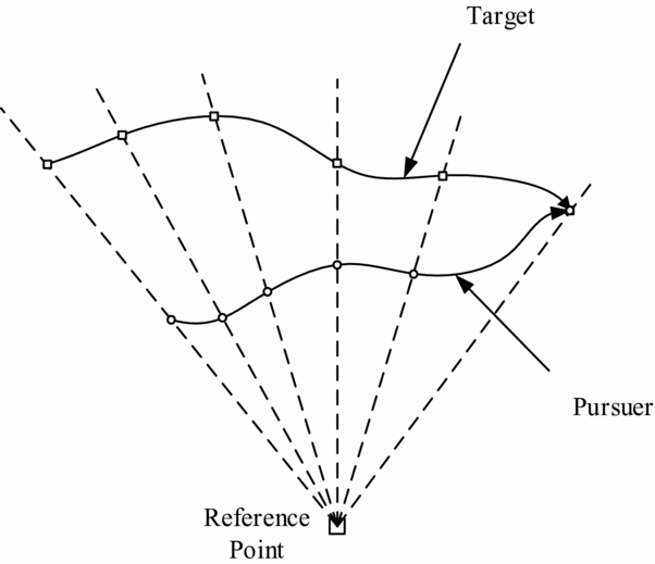
Figure 2. Motion camouflage scenario.
The kinematic models of the missile and target under the Frenet frame are:
 $$\begin{equation}
\left\{ {\begin{array}{@{}*{1}{l}@{}} {{{{\bm{\dot{r}}}}_m} = {v_m}{{\bm{x}}_m}}\\[6pt] {{{{\bm{\dot{x}}}}_m} = {v_m}\left( {{{\bm{y}}_m}{u_m} + {{\bm{z}}_m}{l_m}} \right)}\\[6pt] {{{{\bm{\dot{y}}}}_m} = - {v_m}{{\bm{x}}_m}{u_m}}\\[6pt] {{{{\bm{\dot{z}}}}_m} = - {v_m}{{\bm{x}}_m}{l_m}} \end{array}} \right.{\rm{ }}\left\{ {\begin{array}{@{}*{1}{l}@{}} {{{{\bm{\dot{r}}}}_t} = {v_t}{{\bm{x}}_t}}\\[6pt] {{{{\bm{\dot{x}}}}_t} = {v_t}\left( {{{\bm{y}}_t}{u_t} + {{\bm{z}}_t}{l_t}} \right)}\\[6pt] {{{{\bm{\dot{y}}}}_t} = - {v_t}{{\bm{x}}_t}{u_t}}\\[6pt] {{{{\bm{\dot{z}}}}_t} = - {v_t}{{\bm{x}}_t}{l_t}} \end{array}} \right.,
\end{equation}$$
where, r denotes the position vectors; v denotes the velocity scalar; x is the tangent unit vector of the curve; y is the bi-normal unit vector; z is the normal unit vector; u and l are curvature and torsion, respectively. The subscript m denotes the missile and t denotes the target. In Fig. 1, the vector r without subscript denotes the relative position of the missile and target.
3.0 GUIDANCE LAW IMPLEMENTATION
3.1 Motion camouflage theory
The MC strategy is a new form of stealth strategy which describes the relative motion relationship of the pursuer, target and reference point. Their movement is as shown in Fig. 2:
The pursuer's path is controlled by the path control parameter (PCP) c(t) as:
where x er = x e − x r is the relative distance vector from the reference point to the target. The selected PCP and reference point determines the speed and curvature of the trajectory in the constructed subspace.
If the position of the reference point is a fixed camouflage background, motion camouflage is similar to the three-point guidance law. If the reference point is chosen at infinity, it is similar to the constant-bearing navigation. Therefore, motion camouflage strategy has both features of the three-point guidance law and constant-bearing navigation.
3.2 Guidance law based on motion camouflage
Here, we assume the pursuer and target as the missile and the ground target, respectively. We set the reference point as infinity and yield:
The component of the missile velocity transverse to the baseline (i.e., the relative position vector r ) is:
where
![]() $r = | {\bm r} |$
denotes the magnitude of the baseline.
$r = | {\bm r} |$
denotes the magnitude of the baseline.
Similarly, the transverse component of the target is:
The relative transverse component is:
The missile-target system is in a state of motion camouflage if and only if λ =0.
Considering that the final goal of the guidance problem is to make the relative distance to zero, let
which represents the change rate of the baseline length over the absolute change rate of the baseline vector. If the baseline only lengthens along itself without changing its direction, then Z = +1, which is the maximum value. Similarly, if the baseline only shortens along itself without changing its direction, then Z = −1, which is the minimum value.
Equation (8) can be written as:
Thus, Z is the dot product of two unit vectors: one is in the
![]() ${\bm r}$
direction and the other is in the
${\bm r}$
direction and the other is in the
![]() ${\bm{\dot{r}}}$
direction. According to Equation (7), the magnitude squared of λ is:
${\bm{\dot{r}}}$
direction. According to Equation (7), the magnitude squared of λ is:
 $$\begin{eqnarray}
{\left| {\bf \lambda } \right|^2} &=& |{\bm{\dot{r}}}{|^2} - 2{\left( {\displaystyle\frac{{\bm{r}}}{r} \cdot {\bm{\dot{r}}}} \right)^2} + {\left( {\displaystyle\frac{{\bm{r}}}{r} \cdot {\bm{\dot{r}}}} \right)^2}\nonumber\\
&=& |{\bm{\dot{r}}}{|^2}(1 - {Z^2})
\end{eqnarray}$$
Obviously, the requirement that the transverse component of the missile velocity be equal to that of the target can be transferred to Z = –1. Thus, our objective is to design a guidance law to guarantee Z = –1.
According to the cross-product formula a × ( b × c ) = b ( a · c ) − c ( a · b ), Equation (7) can be transformed into:
Cross-multiply both sides by
![]() ${{\bm r}}/r$
, yielding:
${{\bm r}}/r$
, yielding:
 $$\begin{eqnarray}
{\bf \lambda } \times \displaystyle\frac{{\bm{r}}}{r} &=& \left[ {\displaystyle\frac{{\bm{r}}}{r} \times \left( {{\bm{\dot{r}}} \times \displaystyle\frac{{\bm{r}}}{r}} \right)} \right] \times \displaystyle\frac{{\bm{r}}}{r}\nonumber\\
&=& - \displaystyle\frac{{\bm{r}}}{r}\left[ {\left( {{\bm{\dot{r}}} \times \displaystyle\frac{{\bm{r}}}{r}} \right) \cdot \displaystyle\frac{{\bm{r}}}{r}} \right] + \left( {{\bm{\dot{r}}} \times \displaystyle\frac{{\bm{r}}}{r}} \right)\nonumber\\
&=& {\bm{\dot{r}}} \times \displaystyle\frac{{\bm{r}}}{r}
\end{eqnarray}$$
When selecting the infinity point as the reference point, the relative motion relationship of the missile and the target which satisfies the motion camouflage condition is shown in Fig. 3. In this case, the direction of the baseline is fixed. However, from the sight of the missile, the LOS is rotating with a certain angular velocity and the length of the LOS is changing.

Figure 3. Motion camouflage scenario when the reference point is infinity.
Let
![]() ${\bf \lambda } = {\bf \omega } \times {\bm r}$
, where ω is the angular velocity of the LOS. According to Equation (11) yields:
${\bf \lambda } = {\bf \omega } \times {\bm r}$
, where ω is the angular velocity of the LOS. According to Equation (11) yields:
Therefore, we have:
Let:
Then, the feedback guidance law coefficients can be derived as follows:
where μ is the positive feedback coefficient, and um and lm are curvature and torsion, respectively, which can only change the direction of the velocity.
Submitting Equation (15) into Equation (16) and considering Equation (14) yields:
Thus, the Motion Camouflage Proportional Guidance law (MCPG) can be written as:
which means that the norm of the feedback guidance law coefficients along normal and bio-normal directions is selected as the coefficient of MCPG.
To prove the availability of the MCPG, differentiating Z gives:
 $$\begin{eqnarray}
\dot{Z} &=& \left( {\displaystyle\frac{{{\bm{\dot{r}}} \cdot {\bm{\dot{r}}} + {\bm{r}} \cdot {\bm{\ddot{r}}}}}{{r|{\bm{\dot{r}}}|}}} \right) - \left( {\displaystyle\frac{{{\bm{r}} \cdot {\bm{\dot{r}}}}}{{|{\bm{\dot{r}}}|}}} \right)\left( {\displaystyle\frac{{{\bm{r}} \cdot {\bm{\dot{r}}}}}{{{r^3}}}} \right) - \left( {\displaystyle\frac{{{\bm{r}} \cdot {\bm{\dot{r}}}}}{r}} \right)\left( {\displaystyle\frac{{{\bm{r}} \cdot {\bm{\ddot{r}}}}}{{|{\bm{\dot{r}}}{|^3}}}} \right)\nonumber\\
&=& \displaystyle\frac{{|{\bm{\dot{r}}}|}}{r}\left[ {1 - {{\left( {\displaystyle\frac{{\bm{r}}}{r} \cdot \displaystyle\frac{{{\bm{\dot{r}}}}}{{|{\bm{\dot{r}}}|}}} \right)}^2}} \right] + \displaystyle\frac{1}{{|{\bm{\dot{r}}}|}}\left[ {\displaystyle\frac{{\bm{r}}}{r} - \left( {\displaystyle\frac{{\bm{r}}}{r} \cdot \displaystyle\frac{{{\bm{\dot{r}}}}}{{|{\bm{\dot{r}}}|}}} \right)\displaystyle\frac{{{\bm{\dot{r}}}}}{{|{\bm{\dot{r}}}|}}} \right] \cdot {\bm{\ddot{r}}}
\end{eqnarray}$$
If we define:
Take the second-order derivative on Equation (4) and consider Equation (20), yielding
 $$\begin{eqnarray}
{\bm{\xi }} \cdot {\bm{\ddot{r}}} &=& {{\dot{v}}_m}({\bm{\xi }} \cdot {{\bm{x}}_m}) - {{\dot{v}}_t}({\bm{\xi }} \cdot {{\bm{x}}_t})\nonumber\\
&& + v_m^2\left[ {({\bm{\xi }} \cdot {{\bm{y}}_m}){u_m} + ({\bm{\xi }} \cdot {{\bm{z}}_m}){l_m}} \right]\nonumber\\
&& - v_t^2\left[ {({\bm{\xi }} \cdot {{\bm{y}}_t}){u_t} + ({\bm{\xi }} \cdot {{\bm{z}}_t}){l_t}} \right]
\end{eqnarray}$$
Submitting feedback guidance law coefficients (i.e., Equation (16)) into the second term of Equation (21):
 $$\begin{equation}
\begin{array}{@{}l@{}} v_m^2\left[ {({\bm{\xi }} \cdot {{\bm{y}}_m}){u_m} + ({\bm{\xi }} \cdot {{\bm{z}}_m}){l_m}} \right]\\[6pt] \quad= \mu v_m^2\left[ {({\bm{\xi }} \cdot {{\bm{y}}_m})({\bm{a}} \cdot {{\bm{y}}_m}) + ({\bm{\xi }} \cdot {{\bm{z}}_m})({\bm{a}} \cdot {{\bm{z}}_m})} \right]\\[6pt] \quad= \mu v_m^2({\bm{\xi }} \cdot {\bm{a}}) \end{array}
\end{equation}$$
 $$\begin{eqnarray}
{\bm{\xi }} \cdot {\bm a} &=& - \displaystyle\frac{1}{{|{\bm{\dot{r}}}|}}({\bm{\dot{r}}} \cdot {{\bm{x}}_m})(1 - {Z^2})\nonumber\\
&& + \displaystyle\frac{1}{{|{\bm{\dot{r}}}{|^3}}}\left[ {{\bm{\dot{r}}} \times \left( {{\bm{\dot{r}}} \times \displaystyle\frac{{\bm{r}}}{r}} \right)} \right]\left[ {\left( {{\bm{\dot{r}}} \times \displaystyle\frac{{\bm{r}}}{r}} \right) \cdot {{\bm{x}}_m}} \right]\nonumber\\
& =& - (1 - {Z^2})\left( {\displaystyle\frac{{{\bm{\dot{r}}}}}{{|{\bm{\dot{r}}}|}} \cdot {{\bm{x}}_m}} \right)
\end{eqnarray}$$
The rest of the terms of Equation (21) yields:
 $$\begin{equation}
\begin{array}{@{}l@{}} \left| {v_t^2\left[ {({\bm{\xi }} \cdot {{\bm{y}}_t}){u_t} + ({\bm{\xi }} \cdot {{\bm{z}}_t}){l_t}} \right]} \right| \le \displaystyle\frac{{v_t^2}}{{|{\bm{\dot{r}}}|}}\sqrt {1 - {Z^2}} \max \left( {\sqrt {u_t^2 + l_t^2} } \right)\\ \left| {{{\dot{v}}_m}({\bm{\xi }} \cdot {{\bm{x}}_m}) - {{\dot{v}}_t}({\bm{\xi }} \cdot {{\bm{x}}_t})} \right| \le \displaystyle\frac{1}{{|{\bm{\dot{r}}}|}}\sqrt {1 - {Z^2}} (v_m^ + + v_t^ + ) \end{array},
\end{equation}$$
where v + m and v + t are the upper bounds of vm and vt , respectively. Similarly, we define v − m and v − t as their lower bounds.
Hence,
![]() $\dot{Z}$
can be written as:
$\dot{Z}$
can be written as:
 $$\begin{eqnarray}
\dot{Z} &\le& - (1 - {Z^2})\left[ {\displaystyle\frac{{\mu v_t^2}}{{|{\bm{\dot{r}}}|}}\left( {{v_m} - {v_t}({{\bm{x}}_m} \cdot {{\bm{x}}_t})} \right) - \displaystyle\frac{{|{\bm{\dot{r}}}|}}{r}} \right]\nonumber\\
& + &\displaystyle\frac{1}{{|{\bm{\dot{r}}}|}}\sqrt {1 - {Z^2}} \left[ {v_m^ + + v_t^ + + v_t^2\max \left( {\sqrt {u_t^2 + l_t^2} } \right)} \right]
\end{eqnarray}$$
In the interception process, the relative velocity of the missile and the target should satisfy the following relationship:
where the variable K satisfies
![]() ${{{v_t}} / {{v_m}}} \le K < 1$
.
${{{v_t}} / {{v_m}}} \le K < 1$
.
We define
 $$\begin{equation}
\mu = \left( {\displaystyle\frac{{v_m^ + (1 + K)}}{{{{(v_m^ - )}^3}(1 - K)}}} \right)\left( {\displaystyle\frac{{v_m^ + (1 + K)}}{{{r_o}}} + \sigma } \right),
\end{equation}$$
where ro > 0, σ > 0.
When r > ro and considering Equations (26) and (27), Equation (25) can be written as:
 $$\begin{eqnarray}
\dot{Z} &\le& - (1 - {Z^2})\left[ {\left( {\displaystyle\frac{{v_m^ + (1 + K)}}{{{{(v_m^ - )}^3}(1 - K)}}} \right)} \right.\nonumber\\
&& \times \left( {\displaystyle\frac{{v_m^ + (1 + K)}}{{{r_o}}} + \sigma } \right)\left( {\displaystyle\frac{{{{(v_m^ - )}^3}(1 - K)}}{{v_m^ + (1 + K)}}} \right)\left. { - \displaystyle\frac{{v_m^ + (1 + K)}}{r}} \right]{\rm{ + }}\sqrt {1 - {Z^2}} {\sigma _1}\nonumber\\
& =& - (1 - {Z^2})\sigma {\rm{ + }}\sqrt {1 - {Z^2}} {\sigma _1},
\end{eqnarray}$$
where
![]() ${\sigma _1} = \frac{1}{{|{\bm{\dot{r}}}|}}[ {v_m^ + + v_t^ + + v_t^2\max ( {\sqrt {u_t^2 + l_t^2} } )} ] > 0$
.
${\sigma _1} = \frac{1}{{|{\bm{\dot{r}}}|}}[ {v_m^ + + v_t^ + + v_t^2\max ( {\sqrt {u_t^2 + l_t^2} } )} ] > 0$
.
By choosing μ, we can promise that
![]() $\sigma - {{{\sigma _1}} / {\sqrt {1 - {Z^2}} }} > 0$
. In this way, we have
$\sigma - {{{\sigma _1}} / {\sqrt {1 - {Z^2}} }} > 0$
. In this way, we have
![]() $\dot{Z} < 0$
, which means the feedback guidance law coefficients satisfies the achievement condition of interception. Hence, the MCPG is available.
$\dot{Z} < 0$
, which means the feedback guidance law coefficients satisfies the achievement condition of interception. Hence, the MCPG is available.
3.3 Adaptive motion camouflage proportional guidance law
From the designed guidance law (Equation (18)), we can see that the normal acceleration
![]() ${{\bm a}_{MCPG}}$
is proportional to the relative distance between the missile and the target. So this will lead to a large normal acceleration at the beginning of the terminal guidance. In order to eliminate the adverse effect caused by long distance, the adaptive feedback coefficient μ, which is a function of the relative distance r, is introduced with the following form and is shown in Fig. 4:
${{\bm a}_{MCPG}}$
is proportional to the relative distance between the missile and the target. So this will lead to a large normal acceleration at the beginning of the terminal guidance. In order to eliminate the adverse effect caused by long distance, the adaptive feedback coefficient μ, which is a function of the relative distance r, is introduced with the following form and is shown in Fig. 4:
 $$\begin{equation}
\mu = \left\{ \begin{array}{@{}l@{}} a{r^2} + br + c \quad r > {{{r_0}}
/ {{k_2}}}\\[6pt]
{\mu _0} \quad\quad\quad\quad\quad 0 < r < {{{r_0}}
/ {{k_2}}} \end{array} \right.,
\end{equation}$$
 $$\begin{equation*}
a = \displaystyle\frac{{{\mu _0}\left( {\displaystyle\frac{1}{{{k_1}}} - 1} \right)}}{{r_0^2\left( {1 - \displaystyle\frac{2}{{{k_2}}} + \displaystyle\frac{1}{{k_2^2}}} \right)}},b = - \displaystyle\frac{{2a{r_0}}}{{{k_2}}},c = {\mu _0} + a{\left( {\displaystyle\frac{{{r_0}}}{{{k_2}}}} \right)^2}.
\end{equation*}$$
the μ0 is a positive constant, r 0 is the initial relative distance, k 1 and k 2 are two positive coefficients.

Figure 4. Curve of adaptive feedback coefficient μ.
3.4 Motion camouflage proportional guidance law with impact-angle constraint
For many homing missiles, the terminal impact angle is also an important factor that influences the attack effect in addition to the miss distance. In this section, we derive a closed-form guidance law that considers the impact-angle constraint in the longitudinal plane. The relative motion relationship between the missile and target in the longitudinal plane is shown in Fig. 5.
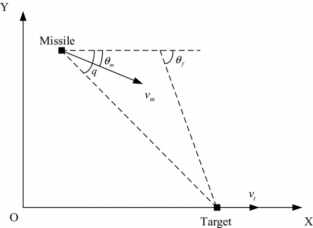
Figure 5. Relative motion relationship between the missile and the target.
Since both the missile and target are abstracted as particles, the guidance law only gives out the normal acceleration command in the longitudinal plane. In Fig. 5, θ m is the flight-path angle of the missile, q is the LOS angle, and θ f is the expected impact angle.
According to the guidance law designed in the previous section, the longitudinal projection of the acceleration command can be written as (considering the lateral projection equals to zero):
Taking the impact angle constraint into consideration, the expected flight-path angle rate command is:
where k is a positive coefficient.
The basic idea of the guidance command is to let the LOS angle track the flight-path angle. The proof of the stability of this guidance law using the Lyapunov theorem is given as follows:
First, we define the angle-tracking error as e = q − θ, then a Lyapunov function is constructed as
![]() ${V_1} = {{{e^2}}
/ 2}$
. To make the system have asymptotic stability, the first-order derivative of V
1 must be negative, i.e.:
${V_1} = {{{e^2}}
/ 2}$
. To make the system have asymptotic stability, the first-order derivative of V
1 must be negative, i.e.:
Assuming that the actuator of the missile is ideal so that the flight-path angle rate command can be tracked perfectly, i.e.,
![]() $\dot{\theta } \equiv {\dot{\theta }_{com}}$
, submitting Equation (31) into Equation (32) yields:
$\dot{\theta } \equiv {\dot{\theta }_{com}}$
, submitting Equation (31) into Equation (32) yields:
 $$\begin{eqnarray}
{{\dot{V}}_1} &=& \left( {q - \theta } \right)\left[ {\dot{q} - \mu \displaystyle\frac{r}{{{v_m}}}\dot{q} - k\left( {q - {\theta _f}} \right)} \right]\nonumber\\
&=& \left( {q - \theta } \right)\left[ { - \displaystyle\frac{{{v_m}\sin \left( {\theta - q} \right)}}{r} + \mu \sin \left( {\theta - q} \right) - k\left( {q - {\theta _f}} \right)} \right]
\end{eqnarray}$$
Considering that the term (θ − q) is really small in the terminal homing phase, the above equation can be approximated as:
From Equation (34), we can see
![]() ${\dot{V}_1} < 0$
if only
${\dot{V}_1} < 0$
if only
![]() $\mu > {{{v_m}}
/ r}$
, whatever the sign of (θ − q). Thus, in order to guarantee the stability of the system, a proper value of μ should be chosen to satisfy the condition
$\mu > {{{v_m}}
/ r}$
, whatever the sign of (θ − q). Thus, in order to guarantee the stability of the system, a proper value of μ should be chosen to satisfy the condition
![]() $\mu > {{{v_m}}
/ r}$
.
$\mu > {{{v_m}}
/ r}$
.
With the relationship
![]() ${a_y} = {v_m}{\dot{\theta }_m}$
, the longitudinal guidance law is turned into the following form:
${a_y} = {v_m}{\dot{\theta }_m}$
, the longitudinal guidance law is turned into the following form:
The last term gcos θ is introduced to eliminate the influence of gravity.
4.0 SIMULATION
4.1 The effect of adaptive MCPG
To verify the validity of the design guidance law, two simulations will be given here: one is the designed MCPG with constant feedback coefficient μ; the other is the adaptive MCPG with variable μ. The initial position and velocity of the missile are r m 0 = [130.5, 5.5, 0.74]km and v m0 = [1428, −630, 714]m/s. The initial position and velocity of the target are r t 0 = [140, 0, 2.7]km and v t0 = [ − 60, 0, 60]m/s. According to Ref. Reference Gao, Li and Jing18, the constant-feedback coefficient MCPG is chosen as μ = 1.4. The simulation results are shown in Figs. 6–9.

Figure 6. The interception trajectories of MCPG and adaptive MCPG.

Figure 7. The feedback coefficient of two guidance laws.

Figure 8. Longitudinal overload.
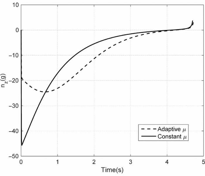
Figure 9. Lateral overload.
As we can see from Fig. 7, the feedback coefficient of the adaptive MCPG is small in the initial phase and increases gradually with the decreasing of distance between the missile and the target, and eventually μ reaches its maximum value and holds this for the remaining flight phase. The adaptive MCPG can significantly reduce the initial overload of the missile in both longitudinal and lateral plane, which can be concluded from Figs. 8 and 9. However, as a price of the small overload, the flight time will be a little longer.
4.2 Adaptive MCPG with impact-angle constraint
The adaptive MCPG with impact-angle constraint is simulated. Here, the simulations are conducted in longitudinal plane. The initial position of the missile is r m0 = [0, 4, 0]km, three different velocities of missile are chosen as Ma=2, Ma=3 and Ma=5 respectively. The target is stationary with position coordinates r t0 = [10, 0, 0]km. The impact angle is selected as 45° for the missile. The simulation results are shown in Figs. 10–13.
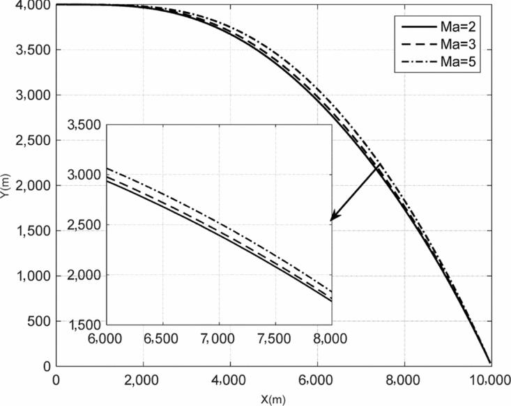
Figure 10. Missile trajectories with different velocities.
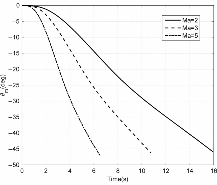
Figure 11. Flight-path angle of the missile with different velocities.

Figure 12. The feedback coefficients with different velocities.

Figure 13. Normal overloads of the missile with different velocities.
Figure 11 shows the flight-path angle of missile with different velocities. The impact angle errors are 0.72°, 1.13° and 1.63°, corresponding to Ma = 2, Ma = 3 and Ma = 5, respectively. It is obvious that the impact angle error increases with the increasing of missile velocity. Figure 12 shows the plot of the feedback coefficients for different velocities. All of the three curves increase with the decreasing of the relative distance between the missile and the target, and become constant when the distance reaches the critical value. From Fig. 13, we can see that higher velocity will result in greater normal overload.
4.3 Comparison of different target motions
Different target motions are selected in this section to compare the performances of the adaptive MCPG with impact angle constraint. Velocity of missile is Ma = 3; the target will have three different manoeuvers: (a) no motion, i.e. the target is stationary as in simulation B; (b) uniform velocity motion with the velocity of 20m/s; and (c) uniformly accelerated motion with the acceleration being 4m/s2 and an initial velocity being 20m/s. The other initial conditions are the same as simulation B. Simulation results are shown in Figs. 14–17.

Figure 14. Missile trajectories with different target motions.

Figure 15. Flight-path angles of missiles with different target motions.
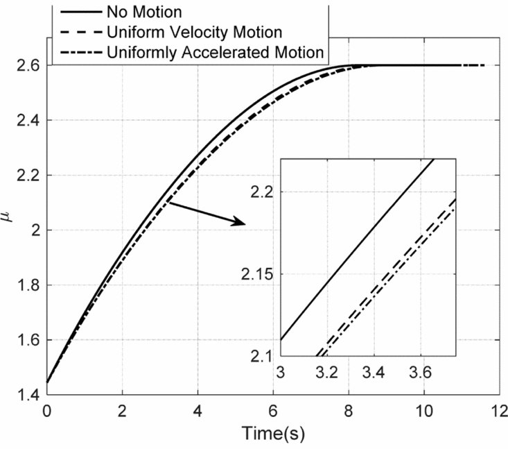
Figure 16. The feedback coefficients with different target motions.
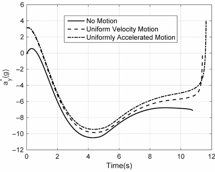
Figure 17. Normal overloads of missile with different target motions.
The impact flight-path angle errors are 1.13°, 0.51° and 1.41° corresponding to no motion, uniform velocity motion and uniformly accelerated motion, respectively. The target manoeuver can increase the tracking error of the impact flight-path angle. From Fig. 17, we can see that the terminal normal overload characteristic has a “jump” because of the motion of the target, which can be attributed to the large LOS angle rate caused by the target motion at the interception point.
4.4 Comparison of different methods
We assume that the measurement accuracy of the seeker is 2° (3σ) and the Pure Proportional Navigation Guidance (PPNG) is used to compare with the proposed method. The guidance coefficient of the PPN is chosen as 3. The flight trajectories for both the PPN and adaptive MCPG are depicted in Fig. 18. Figure 19 shows the comparison of the acceleration of different approaches. Figure 20 contains the variations of flight path angle.

Figure 18. The trajectory of the missile.

Figure 19. The overloads of different methods.

Figure 20. Flight-path angles of different methods.
It can be seen that the trajectory of the adaptive MCPG becomes straighter and the PPN requires a higher acceleration for interception. The flight-path angle of the adaptive MCPG changes more smoothly than that of the PPN. The miss distance of adaptive MCPG and PPN are 0.34m and 0.51m, respectively. Obviously, the adaptive MCPG presents better performance with the uncertainty because it contains the relative distance.
5.0 CONCLUSION
This paper presents a three-dimensional guidance law for intercepting the ground target, which is based on the motion camouflage theory and the Frenet frame dynamic equations. To improve the initial overload characteristic of the guidance law, an adaptive feedback coefficient is introduced. To enhance the practicability, the impact-angle constraint is considered, and hence the adaptive MCPG is transformed to a longitudinal-plane guidance law. According to the simulation, the results show that the adaptive MCPG can significantly reduce the initial overload of the missile comparing with MCPG. Moreover, the adaptive MCPG has a fast response of acceleration and a small overload at the interception moment as the MCPG does. And the expanded impact-angle constraint guidance law can track the final flight-angle perfectly with small error. Moreover, the proposed guidance law does not require too much measurement information so that it is implemented easily for engineering.


