INTRODUCTION
Collimated plasma outflows (jets) are a subject of great interest in the study of astrophysical phenomena (Ryutov et al., Reference Ryutov, Drake and Remington2000; Mizuta et al., Reference Mizuta, Yamada and Takabe2002; Schopper et al., Reference Schopper, Ruhl, Kuzi and Lesch2003; Bellan, Reference Bellan2005), as well as laser plasma interaction phenomena (Hong et al., Reference Hong, He, Wen, Du, Teng, Qing, Huang, Huang, Liu, Wang, Huang, Zhu, Ding and Peng2009). Parameters of the jets produced experimentally in laboratories differ considerably from those observed in the Universe. Astrophysical jets are long, narrowly collimated structures emanating from young stellar objects, black holes, and active galactic nuclei. These exclusively astrophysical phenomena can be, however, simulated by artificially produced plasma jets, provided that their certain dimensionless parameters are comparable. The only tools that are capable of creating conditions for laboratory studies of physical processes taking place in astrophysical objects are pulsed high-power lasers.
The first attempts to use lasers for generation of jets relevant to astrophysical observation were presented only recently (Farley et al., Reference Farley, Estabrook, Glendinning, Glenzer, Remington, Shigemori, Stone, Wallance, Zimmerman and Harte1999; Shigemori et al., Reference Shigemori, Kodama, Farley, Koase, Estabrook, Remington, Ryutov, Ochi, Azechi, Stone and Turner2000). Conically shaped targets made of different materials were irradiated there by five beams of the Nova laser with pulse duration of 100 ps and energy of each beam of 225 J, or by six beams of the GEKKO-XII laser with the same pulse duration, but the total energy of 500 J. Later on, supersonic jet experiments have been conduced on the Omega laser (Coker et al., Reference Coker, Wilde, Foster, Blue, Rosen, Williams, Hartigan, Frank and Back2007; Hartigan et al., Reference Hartigan, Foster, Wilde, Coker, Rosen, Hansen, Blue, Williams, Carver and Frank2009). The titanium assembly in a disk form was irradiated by soft X-ray radiation from a hohlraum laser target being heated by 12 laser beams with a total energy of 6 kJ in 1 ns duration. The directed outflow of shock-heated titanium plasma was collimated by the hole in the titanium washer. Another method of plasma jet generation also worth mentioning consists in creating convergent plasma flows by electrodynamic acceleration of the plasma produced by a conical array of fine wires (Lebedev et al., Reference Lebedev, Chittenden, Beg, Bland, Ciardi, Ampleford, Hughes, Haines, Frank, Blackman and Gardiner2002).
In 2006, we reported a simple method of plasma jet generation based on using a flat massive target with atomic number Z ≥ 29 (Z = 29 corresponds to Cu) irradiated by a single partly defocused laser beam (Kasperczuk et al., Reference Kasperczuk, Pisarczyk, Borodziuk, Ullschmied, Krousky, Masek, Rohlena, Skala and Hora2006).
Our experiments at the Prague Asterix Laser System (PALS) laser facility (Jungwirth et al., 2005) have proved that annular target irradiation plays a decisive role in plasma jet formation (Kasperczuk et al., Reference Kasperczuk, Pisarczyk, Kalal, Ullschmied, Krousky, Masek, Pfeifer, Rohlena, Skala and Pisarczyk2009a). However, this mechanism acts properly only in the case of heavy target materials. If the target is made of light materials like plastic (CH) or Al, no plasma jets are observed, in spite of the initial laser intensity distribution being the same. It is seen in Figure 1, where configurations of CH, Al, and Cu plasmas at the focal spot diameter ΦL= 600 µm are presented. One can see that with growing target atomic number the plasma stream becomes narrower. However, good quality plasma jets can be launched on Cu targets only.

Fig. 1. (Color online) Sequences of electron density distributions of plasma streams presented in form of electron equidensitograms for targets made of (a) CH, (b) Al, and (c) Cu. The outer plasma contour corresponds to the electron equidensity line 1018 cm−3, the distance between adjacent lines being equal to 2 × 1018 cm−3.
Although our experimental results demonstrated that it is impossible to launch a plasma jet on low-Z material targets like CH (CH, Z = 3.5), our investigations of the plasma stream emitted from a joint of light and heavy target materials (Al-Cu or CH-Cu) (Pisarczyk et al., Reference Pisarczyk, Kasperczuk, Kalal, Gus'kov, Ullschmied, Krousky, Masek, Pfeifer, Rohlena, Skala and Pisarczyk2008) suggested that a low-Z plasma component could improve plasma jet parameters. Namely, in that case, the plasma jet is not propagating normally to the target surface, but it is deflected to the side of the heavier material. The angles of jet deflection for Al-Cu and CH-Cu joints were about 5° and 10°, respectively. Recently, we presented theoretical analysis of the dynamics of plasmas produced by laser on targets consisting of CH and Cu (Kasperczuk et al., Reference Kasperczuk, Pisarczyk, Badziak, Borodziuk, Chodukowski, Gus'kov, Demchenko, Ullschmied, Krousky, Masek, Pfeifer, Rohlena, Skala and Pisarczyk2010). This analysis allowed us to evaluate the average pressures in CH and Cu plasmas near the critical densities during the period of laser action. They are equal to 14.3 Mbar and 10.6 Mbar, respectively.
The ratio of CH and Cu plasma pressures amounts to 1.35. We have decided, therefore, to exploit that difference in plasma pressures for generating plasma jets with better parameters (smaller diameter and higher plasma density) than those obtained hitherto. For that purpose, we have designed a target in which a central cylindrical insert made of high-Z material (Cu) is fixed in a low-Z material (CH), expecting that the surrounding light plasma would compress the plasma jet produced from the insert. That assumption has been confirmed by a successive experiment (Kasperczuk et al., Reference Kasperczuk, Pisarczyk, Badziak, Borodziuk, Chodukowski, Gus'kov, Demchenko, Ullschmied, Krousky, Masek, Pfeifer, Rohlena, Skala and Pisarczyk2010).
Both the experimental results and the theoretical analyses, described above, allowed us to conclude that the lighter the plasma the higher the pressure, and made us to pose a question about the possibility of creating Al plasma jet by using CH plasma as a compressor. If the laser target is provided by a central cylindrical insert made of higher-Z material (Al), which is fixed in a lower-Z material (CH), then the plasma stream produced from the insert should be constrained by the surrounding lighter plasma. As a result, smaller diameter of the Al plasma stream and higher plasma density, comparable with that obtained in the case of pure Cu plasma, should be expected. The idea of Al plasma jet creation with the use of the CH plasma as a compressor is sketched out in Figure 2. This paper is aimed at validating that idea.

Fig. 2. (Color online) The idea of experiment: the CH plasma as a compressor of the Al plasma.
EXPERIMENTAL SETUP AND CONDITIONS
The reported experiment was carried out with the use of the PALS iodine laser facility (Batani et al., Reference Batani, Dezulian, Redaelli, Benocci, Stabile, Canova, Desai, Lucchini, Krousky, Masek, Pfeifer, Skala, Dudzak, Rus, Ullschmied, Malka, Faure, Koenig, Limpouch, Nazarov, Pepler, Nagai, Norimatsu and Nishimura2007; Laska et al., Reference Laska, Krasa, Velyhnan, Joungwith, Krousky, Margarone, Pfeifer, Rohlena, Ryc, Skala, Torrisi and Ullschmied2009; Torrisi et al., Reference Torrisi, Margarone, Laska, Krasa, Velyhan, Pfeifer, Ullschmied and Ryc2008). The plasma was generated by a laser beam with a diameter of 290 mm, which was focused by means of an aspheric lens with a focal length of 600 mm for the third harmonic of the laser radiation used (λ = 0.438 µm). The following laser parameters have been chosen: laser energy 130 J, focal spot diameters (ΦL) 800, 1000, and 1200 µm (the focal point being located inside the target), and pulse duration 250 ps (FWHM). The laser irradiated a CH target with an Al cylindrical insert of 400 µm in diameter. The Al plasma stream propagation and its interaction with CH plasma were studied by means of a three-frame interferometric system and a four-frame pinhole camera imaging system in the soft X-ray domain. The three-frame interferometric system was operated at the second laser harmonic, wavelength 0.638 µm. The X-ray camera with a pinhole 80 µm in diameter registered soft X-ray plasma radiation in the range of 10–1000 eV. The exposure time of the X-ray camera was below 2 ns.
INVESTIGATIONS OF THE AL PLASMA COMPRESSION BY THE CH PLASMA
To ensure a predominance of the CH plasma amount is high enough for the effective Al plasma compression, we started our investigations with ΦL = 800 µm. Then, the focal spot diameter was gradually increased by 200 µm up to 1200 µm. They correspond to the ratios of the irradiated CH and Al surfaces of 3, 5.25, and 8. The interferometric measurements have shown that the Al plasma compression grows with increasing the focal spot diameter. This is demonstrated in Figure 3, where the diagrams of electron density distribution along the plasma plume axis at 10 ns for all the focal spot diameters used is plotted. One can see that the highest electron density corresponds to the greatest ΦL. Therefore, in what follows only the results obtained for ΦL = 1200 µm will be discussed.

Fig. 3. (Color online) Diagrams of electron density along the axis for different focal spot diameters.
One can suppose that the axial plasma component consists of the pure Al plasma. However, it is impossible to distinguish the Al plasma from the whole plasma by interferometry. For this reason the X-ray frame camera was used, which is able to recognize the Al and CH plasma components due to a large difference in the radiation intensity of these plasmas. The exemplary results are presented in Figure 4.

Fig. 4. (Color online) Sequences of X-ray plasma images for Al target (a) and CH target with Al cylindrical insert (b).
Let us underline the most important finding coming from these X-ray plasma images. One can see that the Al plasma jet in the form of the narrow bright streak can be clearly distinguished on the CH plasma background. The constrained Al plasma jet starts very early just near the target surface. Its diameter is approximately equal to 100 µm and it propagates with an average velocity of 7 × 107 cm/s. This velocity is considerably greater than the axial velocity of the Al only plasma (~5 × 107 cm/s). It means that the interaction of the CH-Al plasmas results in not only the Al plasma jet creation but also its acceleration.
Being sure that the narrow central plasma component consists of the pure Al plasma we can continue the analysis of interferometric results. In Figures 5 and 6, the sequences of interferograms and electron density distributions corresponding to them are presented. Great differences are seen between the plasma configurations corresponding to the pure Al plasma and the composition of Al and CH plasmas, observed at t = 10 ns. The former conserves its divergent structure during the whole observation period, whereas in the latter the initial divergent plasma expansion becomes convergent at later times.

Fig. 5. The sequences of interferograms corresponding to ΦL = 1200 µm, where (a) the Al target, (b) the CH target with Al insert.

Fig. 6. (Color online) The electron density distributions for the Al target (a) and the CH target with Al insert (b) computed on the basis of the above interfeograms. The outer plasma contour corresponds to the electron equidensity line 1018 cm−3, the distance between adjacent lines being equal to 2 × 1018 cm−3.
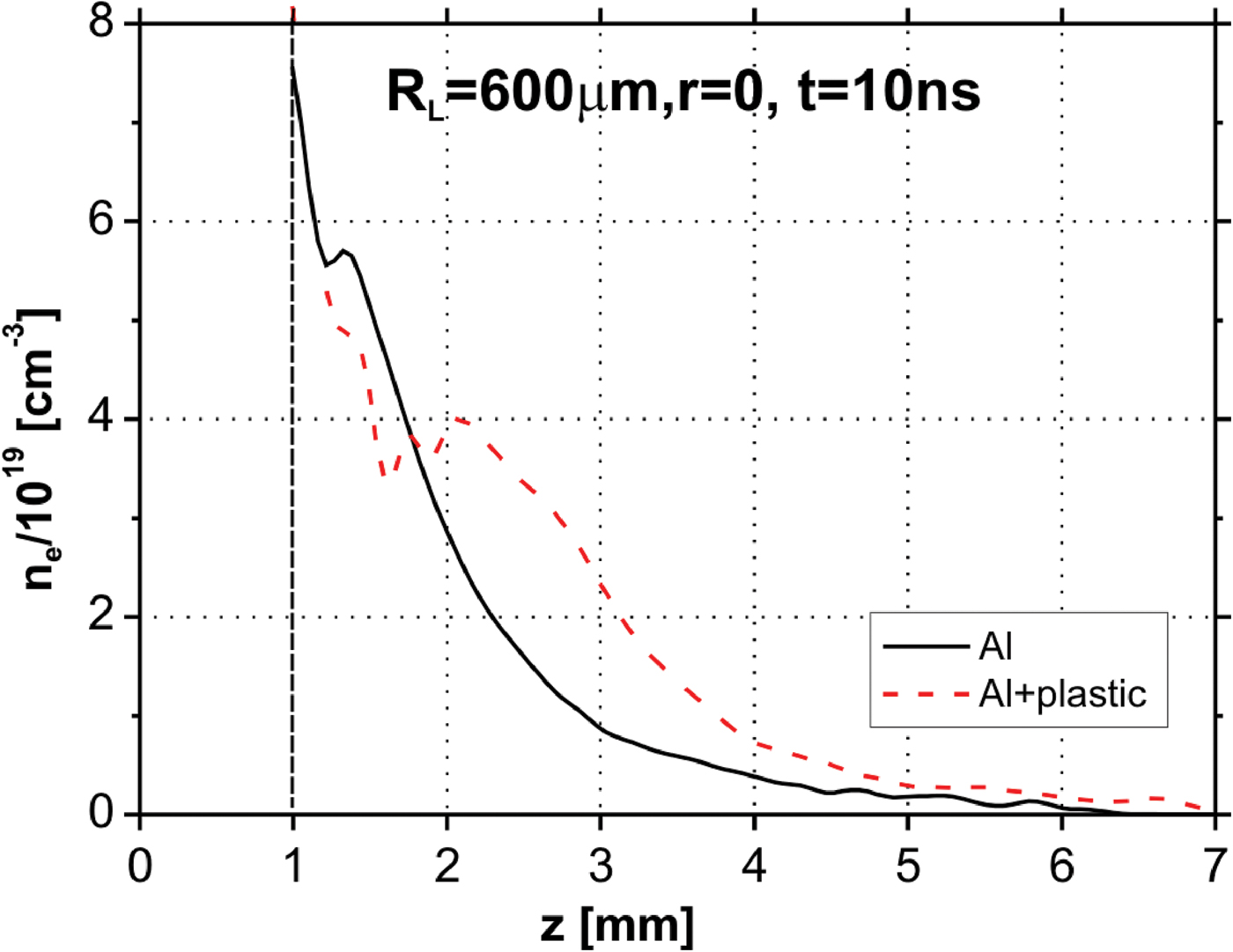
In Figure 7, the diagrams of the electron density distributions along the axis for the Al target and the CH target with the Al insert are drawn. As it is seen, the Al plasma compression leads to the increase of electron density at the axis for z > 2 mm, by a factor of two in comparison with the electron density of the plasma launched on the Al target.

Fig. 7. (Color online) Diagrams of the electron density distributions along the axis for the Al target and the CH target with Al insert.
However, the lifetime of such a plasma configuration is relatively short. The interferograms recorded at later instants (t ≥ 10 ns) show that the plasma compressed earlier expands radially with a velocity of 2.7 × 107 cm/s (see Fig. 8), which leads to the electron density decrease at the axis. Changes of the electron density at the axis for both the targets used versus time corresponding to z = 2.1 mm, i.e., to the electron density local maximum (see Fig. 7), are presented in Figure 9. One can see that the Al plasma compression at this cross-section lasts about 10 ns. Later on, the electron density drops drastically, even below the value proper for pure Al plasma.

Fig. 8. Sequence of interferograms illustrative of the Al plasma jet expansion at later instants.

Fig. 9. (Color online) Diagrams of the electron densities change vs. time for both the target used.
THEORETICAL ANALYSIS OF THE EXPERIMENTAL RESULTS
In our earlier paper (Kasperczuk et al., Reference Kasperczuk, Pisarczyk, Demchenko, Gus'kov, Kalal, Ullschmied, Krousky, Masek, Pfeifer, Rohlena, Skala and Pisarczyk2009b), it was demonstrated that at the same conditions of irradiation of two similar targets, which differ in atomic number only, the interaction with the lighter one is characterized by smaller evaporated mass and larger plasma expansion velocity. According to that paper, the ratio of evaporated masses of Al and CH, per irradiated surface unit in g/cm2, Δm Al and Δm CH, can be estimated by the following formula:

where: χ = κρ/C V —coefficient of thermal conductivity, ρ — initial target density, C V – specific heat, κ — Spitzer's coefficient of electron heat conductivity expressed in the form:
here T e is the electron temperature in eV, m e and e are the mass and charge of the electron, respectively, Λ is the Coulomb logarithm, Z* and Z 2* are the charge and squared charge of ions averaged over the different types of ions.
The estimation gives Δm Al/Δm CH = 1.99. Because at later time the energy absorbed by plasma is completely transformed into the kinetic energy of plasma expansion, Δm(u 2)*/2 = E a/S f, where (u 2)* is the square of plasma velocity averaged from the mass point of view, E a — the absorbed energy, and S f -surface of target irradiation. As a result, the estimation of the ratio of CH and Al plasma expansion velocities gives the value u*CH/u*Al = Δm Al/Δm CH)1/2 = 1.41. Here, ![]() . However, the expansion velocity profiles of different materials have the same form; therefore, the ratio of their velocity maximums has also the same value of 1.41. Since the CH plasma overtakes the Al one, it induces an enhancement of the CH plasma pressure beyond the pressure of Al plasma, which results in the plasma motion towards the axis. The contact boundary of both the plasmas is deflected from the normal to the target surface by a certain angle α. This angle depends on the difference in initial densities of the target materials used. For example, the boundary of CH-Cu plasmas is deflected by 10°, whereas the boundary of Al-Cu plasmas by 5°. For the combination of CH-Al, which is close to the case of Al-Cu from the density ratio point of view, we should obtain roughly α = 5°. As the plasma motion is directed both along the axis z and toward the axis z (i.e., along the radius r), the Al plasma should be focused at the distance z f = R Al/t gα = 2.3 mm, where R Al = 200 µm is the initial radius of Al insert. This situation corresponds to the diagram in Figure 7. The evaporated masses of CH and Al materials amount to: Δm CH = 2.4 × 10⁻⁴ g/cm2, and Δm Al = 4.78 × 10⁻⁴ g/cm2, and the average velocity of Al plasma (in the above mentioned sense) u*Al = 2.19 × 107 cm/s. Because this velocity is characteristic for the whole evaporated mass, then the point at the distance z = 2.1 mm corresponds to the instant of 9.6 ns in Figure 9, i.e., when the plasma density reaches its maximum. Thus, there is a good accordance of the theoretical valuation and the experimental result.
. However, the expansion velocity profiles of different materials have the same form; therefore, the ratio of their velocity maximums has also the same value of 1.41. Since the CH plasma overtakes the Al one, it induces an enhancement of the CH plasma pressure beyond the pressure of Al plasma, which results in the plasma motion towards the axis. The contact boundary of both the plasmas is deflected from the normal to the target surface by a certain angle α. This angle depends on the difference in initial densities of the target materials used. For example, the boundary of CH-Cu plasmas is deflected by 10°, whereas the boundary of Al-Cu plasmas by 5°. For the combination of CH-Al, which is close to the case of Al-Cu from the density ratio point of view, we should obtain roughly α = 5°. As the plasma motion is directed both along the axis z and toward the axis z (i.e., along the radius r), the Al plasma should be focused at the distance z f = R Al/t gα = 2.3 mm, where R Al = 200 µm is the initial radius of Al insert. This situation corresponds to the diagram in Figure 7. The evaporated masses of CH and Al materials amount to: Δm CH = 2.4 × 10⁻⁴ g/cm2, and Δm Al = 4.78 × 10⁻⁴ g/cm2, and the average velocity of Al plasma (in the above mentioned sense) u*Al = 2.19 × 107 cm/s. Because this velocity is characteristic for the whole evaporated mass, then the point at the distance z = 2.1 mm corresponds to the instant of 9.6 ns in Figure 9, i.e., when the plasma density reaches its maximum. Thus, there is a good accordance of the theoretical valuation and the experimental result.
Now, let us estimate theoretically the growth of electron density of Al plasma due to radial compression, so as to compare it with that shown for z f = 2.1 mm in Figure 9. The plasma temperature in this plasma region is about 100 eV. The electron densities corresponding to the case without and with the plasma radial compression are equal to n e0 = 2.5 × 1019 cm−3 and n e1 = 4 ×1019 cm−3, respectively. At the end of the focusing process, the plasma becomes reflected at the axis and the plasma radial velocity changes its sign. The velocity increase amounts to 2u r, where u r = u*Al × t g5° = 1.92 × 106 cm/s. In order to estimate the plasma momentum, the following value is taken into consideration: Δm rAl = ρAlR Al, where ρAl — the Al plasma density corresponding to the electron density of Al plasma without compression (2.5 × 1019 cm−3). The plasma momentum change results from the pressure increase inside the compressed plasma area in comparison with the “undisturbed” pressure, i.e., with case when there is no radial compression. The time-averaged plasma pressure at the axis in the case of the radial compression can be estimated as (p 1 + p 0)/2, where p 1 = p 0(ρ1/ρ0)γ. Due to the low plasma temperature, the thermal conductivity can be neglected. Difference in the plasma pressures (p 1 + p 0)/2 − p 0 = (p 1 − p 0)/2 leads to the plasma reflection from the axis. So, the equation for the plasma momentum can be written as follows:
where: Δt = R Al/c s, c s= 8.43 × 106 cm/s — sound speed. The Eq. (3) allows to get the compression value ρ1/ρ0 = 1.7, which is close to the experimental value n e1/n e0 = 1.6 at the instant of 10 ns, taken from Figure 9.
CONCLUSIONS
In this work, we have demonstrated the possibility to create Al plasma jets by using CH plasma as a compressor. In our experiments, we took advantage of the fact that the lighter the plasma is, the higher is its pressure. The reported measurements prove that the Al plasma jet produced inside the CH plasma envelope is very narrow and its axial velocity is greater than the velocity of pure Al plasma. It means that the CH plasma accelerates the Al plasma also in the axial direction. On the basis of theoretical analysis one can conclude that the difference in plasma pressure related to plasmas with different atomic numbers results from differences in their expansion features. In particular, the plasma velocities differ considerably. Our estimation of the ratio of the CH and Al plasma expansion velocities gives the value of 1.41. As a result, the CH plasma overtakes the Al one, and its pressure, which becomes higher than that of Al plasma, compresses the Al plasma towards the axis.
ACKNOWLEDGEMENTS
The authors gratefully acknowledge the support of this work received from the EC 7th FP under Grant Agreement Number 228334 (Laserlab-Europe), from the Czech MSMT under the grants Numbers LC528 and 7E09092 and from the Ministry of Science and Higher Education MNiSZW, Poland, under Grant Number N N202 130639.