


I. INTRODUCTION
In recent years, left-handed materials (LHM) have been studied extensively. The most interesting physical feature of LHM is the negative refractive index. In ordinary materials both the permittivity and the permeability are positive; whereas, LHM possess negative permittivity or negative permeability or both. The concept of LHM was first put forward in 1986 by Veselago [Reference Veselago1]. In 1999, Pendry proposed the theoretical model of realizing LHM based on metal wire and split ring resonators (SRRs) [Reference Labidi, Tahar and Choubani2]. This element creates more of its resonance, a negative effective permeability in a narrow frequency band around its resonance. Another advantage of this resonator is its small size, in fact, the largest dimensions of this resonator are in the order of λ/10. They are composed of single or double split rings, in square or circular forms. The single split-ring resonators have been employed and many detailed studies have been provided in terahertz frequency range about the electric and magnetic resonances of SRRs [Reference Rockstuhl3, Reference Hsieh and Chang4]. Consequently, it would be highly desirable to derive simple analytical expressions to calculate the resonant frequency from the parameters of the structure. Limited research has been performed on the circular SRR structure and in literature there is no published papers performed on the SRR array deposited on substrate. In addition, the transmission line analysis has been used to extract the equivalent lumped-element circuit for SRR with large open ends of the rings [Reference Du5]. Moreover, an analytical formula has been derived for a single SRR in air [Reference Rockstuhl3, Reference Sydoruk6]. In this paper, an accurate and simple LC model is proposed to study the behavior of the metamaterials based on SRR, which is extracted from the geometric parameters. Moreover, we describe the effect of many parameters (substrate type, gap width and lattice constant) on the behavior of the structure.
The equivalent LC parameters of the proposed structure will be derived using constitutive equations and a comparison between simulations and calculations results will be provided. The resonant frequency of the ring is expressed as
 $\; f_0 = 1/\left( {2 \times \pi \sqrt {LC}} \right)$
, it would be desirable to derive theoretical expressions in order to calculate the resonant frequency from the geometrical parameters of the SRR.
$\; f_0 = 1/\left( {2 \times \pi \sqrt {LC}} \right)$
, it would be desirable to derive theoretical expressions in order to calculate the resonant frequency from the geometrical parameters of the SRR.
The most and first significant parameter that influences the capacitance C and eventually the resonant frequency is the type of the substrate. The second parameter is the gap width. Hence, the capacitance of the ring increases and the resonant frequency decreases. Noticing that the high intensity of the electric field is in the gap of the SRR for this reason the gap width should be properly optimized. The third parameter considered is the lattice constant. To evaluate our study, we also present a comparison of both simulations and calculations results.
The remainder of this paper is organized as follow: Section II presents the proposed analytical model. Comparisons between the simulated results obtained from CST Microwave software and theoretical results obtained from the proposed analytical model are shown in Section III and the influence of some parameters is discussed in this section. Finally, in Section IV the conclusion of this work will be highlighted.
II. ANALYTICAL MODEL OF CIRCULAR SRR
In the LHM based on SRR, induced currents in the metallic ring present a significant and important magnetic response of the SRRs, which are forced to oscillate due to the gaps considered as capacitor [Reference Ozbay, Guven and Aydin7, Reference Rosa and Grover8]. Figure 1 presents the geometrical parameters of the structure; it consists of copper circular split rings resonator deposited on substrate. The geometric parameters of the circular rings are sketched in the caption of Fig. 1 (r o and r i are respectively the inner and the outer radii of the ring, w and t represent respectively the width and the thickness of the ring, g presents the gap width, finally l and h are the width and the height respectively of the substrate).

Fig. 1. Geometrical parameters of SRR (r 0, r 1, w, g, t, l, and h).
For the simulations, the incident electromagnetic wave propagates along the x-direction, the electric field (E) is kept along the y-direction and the magnetic field (H) is kept along the z-direction.
The SRR is described by two elements: the capacitance C and the inductance L. First, many formulas have been given to calculate the mutual and the self inductance (L m and L s ) of electrical circuits [Reference Grover9]. Secondly, the total capacitance is defined as the gap capacitance (C g ), the surface capacitance (C s ) and the coupling capacitance (C c ). The resonant frequency can be calculated using the following formula [Reference Grover9]:
 $$w_0 = \displaystyle{1 \over {\sqrt {\left( {L_s + 4L_m} \right)\left( {C_s + C_c + C_g} \right)}}}, $$
where L s can be expressed as [Reference Grover9]:
 $$L_s = \mu _0 r(\log \left( {\displaystyle{{2r} \over w}} \right) + 0.9 + 0.2\left( {\displaystyle{w \over {2r}}} \right)^2, $$
with r the mean radius of the ring. To calculate the mutual inductance between the rings, Rosa and Grover [Reference Grover9] suggest two circles with a rectangular section that can be replaced by circular filaments as shown in Fig. 2. The distance between the filaments is given by δ:
 $$\delta = 2\sqrt {\displaystyle{{w^2 - t^2} \over {12}}}. $$
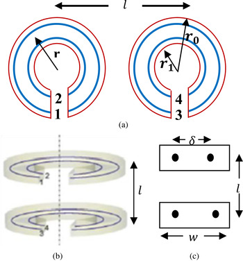
Fig. 2. (a) SRR replaced by filaments 1, 2, 3, and 4. (b) Filaments and SRR in coaxial position. (c) Cross-section of (b).
The famous formula for the mutual inductance of coaxial circles is that in elliptic integrals given by Maxwell [Reference Grover10]:
 $$M_0 = 4\pi \sqrt {a_1 a_2 \left[ {\left( {\displaystyle{2 \over k} - k} \right)F - \displaystyle{2 \over k}E} \right]}. $$
In witch (a 1 = r + δ/2) and (a 2 = r − δ/2) are the radii of the two circles, l is the distance between their centers. F and E are the elliptic integrals of the first and second kinds, respectively, for the modulus k, which is defined as:
 $$k = \displaystyle{{2\sqrt {a_1 a_2}} \over {\left( {a_1 + a_2} \right)^2 \, + \, l^2}}. $$
Then, as described by Grover [Reference Grover10], the value of M 0 is multiplied by a factor F given as follows:
 $$M = M_0 F, $$
where F depends on the value of the ratio of (2a/l). The values of F are given in Table 1 (table excerpted from Table 43 of [Reference Rosa and Grover8]).
Table 1. Values of F.

As suggested by Rosa et al. [Reference Rosa and Grover8], the total mutual inductance between the rings is obtained by mean of the four inductances M 13, M 14, M 23, and M 24, where for instance, M 24 is the mutual inductance of filaments 2 and 4.
To calculate the total capacitance, Sydoruk et al. [Reference Sydoruk6] presented a simple analytical approximate expression to calculate a capacitance. First, the surface capacitance is determined analytically using theoretical expressions for the electric field of a split ring, and it is expressed by:
 $$C_s = \; \displaystyle{{2\varepsilon _0 \left( {t + w} \right)} \over \pi} {\rm log}\displaystyle{{4r_i} \over g}. $$
Secondly, as presented in [Reference Ghosh and Chakrabarty11], the coupling capacitance between the rings is estimated using the rectangular subdomain modeling method where surfaces are modeled by planar rectangular subdomains in which the charge density is assumed to be constant as shown in Fig. 3 and the surface capacitance is expressed by Ghosh and Chakrabarty [Reference Ghosh and Chakrabarty11]:
 $$C_c = \displaystyle{1 \over {\left( {2/C_{r1}} \right) + \left( {2/C_{r2}} \right)}}, $$
 $$C = \displaystyle{{\varepsilon _0 L} \over 2}\left[ {\displaystyle{{K(K^{\prime}_0 )} \over {K(K_0 )}} \, + \varepsilon _r \displaystyle{{K(K^{\prime}_1 )} \over {K(K_1 )}}} \right], $$
where K(K
0),
 $K(K^{\prime}_0 )$
, K(K
1), and
$K(K^{\prime}_0 )$
, K(K
1), and
 $K(K^{\prime}_1 )$
are the complete elliptic integrals of the first kind with
$K(K^{\prime}_1 )$
are the complete elliptic integrals of the first kind with
 $k^{\prime}_0 = \; \sqrt {1 - k_0^2} $
and
$k^{\prime}_0 = \; \sqrt {1 - k_0^2} $
and
 $k^{\prime}_1 = \; \sqrt {1 - k_1^2} $
. k
0 and k
1 are given by the following expressions:
$k^{\prime}_1 = \; \sqrt {1 - k_1^2} $
. k
0 and k
1 are given by the following expressions:
 $$k_0 = \; \displaystyle{{W_s} \over {2W_L + W_s}}, $$
and
 $$k_1 = \displaystyle{{{\rm tanh}\left( {\pi W_s /4h} \right)} \over {{\rm tanh}\left( {\left[ {\pi \left( {2W_L + W_s} \right)} \right]/4h} \right)}}\;, $$
where W s presents the gap between the plates, W L is the width of the plates, and L presents the length of the plates. These parameters are indicated in Fig. 4. Moreover, Table 2 lists the expressions of W s and W L for each capacitance.

Fig. 3. Representation of SRR into rectangular subdomain.

Fig. 4. Top view of two strips on a substrate.
Table 2. Capacitance parameters.

III. STUDY OF VARIOUS PARAMETERS ON THE SRR
In this study, parameters of the structures are optimized to operate in the frequency range of 60–170 GHz as shown in Table 3. All the samples in Table 3, using listed geometrical parameters, have been simulated. In order to ensure the reliability of our approach, several simulations are performed to evaluate the impact of the mesh size on the resonant frequency. We can clearly see the impact of the mesh size on the simulation results: increasing the mesh cells leads to decrease the mesh size. However, to have a good agreement and a stability of the resonant frequency we increase the number of mesh cells (in this case, the mesh size is about 6 μm). Figure 5 shows the simulated transmission spectrum of three samples. We notice from the LC resonance frequency, that excitation by the electric field giving a circular current in the coil, leads to an oscillatory magnetic dipole moment perpendicular to the SRR plane. Table 4 presents a comparison of the simulated data of the samples with the theoretical results computed using the proposed analytical model reported in the previous section. Table 4 shows a good matching between the calculated and the simulations results with maximum error of 4.23%, confirming hence consistency of the proposed model.

Fig. 5. Simulated insertion loss of the samples.
Table 3. Designing parameters of SRR.

Table 4. Comparison of simulations and calculations.

As shown in Fig. 5, it is observed that the quartz gives stronger resonance than that of silicon. That is due to the loss which increases for the resistivity of silicon substrate. Moreover, the resonant frequency of the sample 3 “Quartz” is shifted upwards at about 140 GHz.
A) Effect of the substrate type
The SRR can be modeled as a LC circuit with a resonant frequency of the ring expressed as f 0 = 1/LC. As described in the previous section, the type of substrate is a very important factor influencing the capacitance C and as a consequence of the resonant frequency. Physically, high-permittivity materials allow more field flux. Consequently, the capacitance reduces the resonant frequency. Moreover, the resistivity (or inversely the conductivity) of the substrate also has an impact on the resonance behavior. Figure 6 depicts the calculated and simulated transmission spectrum for several values of permittivity.

Fig. 6. Effect of the substrate permittivity on the resonance frequency of SRRs (r o = 140 μm, r i = 70 μm, g = 20 μm, l = 300 , t = 0.75 μm, and h = 300 μm).
As shown in Fig. 6, we confirm the effectiveness of the analytical approach owing to a maximum error of about 2.3%.
B) Effect of the gap width
In this section, the second factor “gap width” that influences the resonance frequency will be presented. However, as the gap width becomes smaller the mesh density strongly influences the simulation results. Hence, the capacitance of the ring increases and as a consequence, the resonant frequency decreases. Part of them propagates down in the substrate producing more loss. As the gap becomes larger the electric field lines between the plates will be straighter and then loss reduces. Therefore the gap width should be properly optimized for good radiation efficiency.
Figure 7 compares the calculated and simulated insertion loss of the SRR with several values of the gap keeping other geometric parameters, which are described in the caption of the figure. It can be seen that, the resonant frequency increases with the gap width. However, increasing the gap reduces the capacitance and consequently increases the resonant frequency. As shown in Fig. 7, it can be confirmed that, the results agree reasonably with a maximum error of 18% for the lowest values of the gap (g) and the error obtained at g = 50 μm drops down to about 4%.

Fig. 7. Simulations and analytical results comparison of the resonant frequency as function of the gap width (r o = 140 μm, r i = 70 μm, l = 300 μm, t = 0.75 μm, and h = 300 μm).
C) Effect of the lattice constant
In order to investigate the effect of the coupling, we make several samples with the same geometric parameters. The only changing parameter is the lattice constant.
The dependence of the resonant frequency on the lattice constant is shown in Fig. 8. It is observed that the resonant frequency is unaffected by the variation of lattice constant. The simulation results are compared with the calculated data and a good fitting has been obtained with a maximum error of 0.4%. We can conclude from these results that the approach of sub-domain modeling can be used effectively. Despite the coupling capacitance presents about 20% of total capacitance, our theoretical model provides a good agreement.

Fig. 8. Simulations and analytical results comparison of the resonant frequency of SRRs as function of the lattice constant (r o = 140 μm, r i = 70 μm, g = 20 μm, t = 0.75 μm, and h = 300 μm).
IV. CONCLUSION
Simple and accurate analytical models for the capacitance and inductance of a circular SRR are presented. The former have been validated by several parametric simulations. The resonance behavior is shown to be highly dependent on the gap width and the substrate permittivity and a good agreement between the theoretical and simulations results has been achieved.
 Mondher Labidi was born in 1980. He received the M.S degree in telecommunication from the Higher School of Communications “Sup’com”, Tunisia, in 2008 and Ph.D. degree in Information technology and telecommunications from Sup’com, Tunisia, in 2012. Now, member of Innov’com Research laboratory and assistant professor in a National Institute of Applied Sciences and Technology, Tunisia.
 Fethi Choubani was born in Mahdia (Tunisia) in 1961. He received the electrical engineering diploma from Ecole Nationale d’Ingenieurs de Tunis, Tunisia in 1987 and the M. Eng and Ph.D. degrees from ENSEEIHT, Institut National Polytechnique de Toulouse, Toulouse, France in 1988 and 1993 respectively.
Since 1993, he has been with Sup’Com, Ecole supérieure des Communications de Tunis as an Assistant, Associate and then Professor where he taught Radiofrequency components and devices, propagation and antennas, and ElectroMagnetic Compatibility.
His main interests are focused on oscillators and their applications to electromagnetic sensors, EMC, nonlinear devices, modeling of passive, active components and RF techniques and measurements.
He has been offered a position of visiting Research Professor in the Department of Electrical and Computer Engineering at the University of Illinois at Urbana-Champaign in 1999 during 3 months, and in Laplace laboratory in ENSEEIHT for one month.
He was Head of the Telecommunications Department, ESPTT (Tunisia) from 1995 to 1996, Director of Strategic studies, Tunisia Telecom (Tunisian operator in Telecommunications) during 1999–2001, Director of High Institute of Technological studies from during 2010–2011 and advisor of ICT Minister during 2012–2014.
He has published more than 100 journal and international conference papers.


