Introduction
Antenna radar cross-section (RCS) reduction has become an important research focus, particularly for military applications. While RCS is the dominant scattering source, which is not conducive to stealth performance for the military platforms [Reference Panda and Ghosh1–Reference Zhang2]. Therefore, it is important to reduce antenna RCS while maintaining radiation performance.
Antenna RCS reduction has been widely studied in the last decade, and proposed RCS reduction methods can be divided into three categories on the basis of their underlying mechanism. Metamaterials is the most widely used method, including partially reflecting surfaces, metasurfaces, frequency selective surfaces, etc. [Reference Panda and Ghosh1–Reference Joozdani, Amirhosseini and Abdolali7]. Microstrip patch antenna covered by a partially reflecting surface to reduce out-of-band RCS [Reference Jiang, Xue, Li, Ren and Cao5] had achieved average out-of-band RCS reduction of 13 dB while maintaining radiation performance. However, antenna volume was significantly increased. Anisotropic metasurfaces reduced in-band RCS for a waveguide slot array [Reference Zhao, Gao, Cao, Liu, Xu, Liu and Cong8], and the reduction was polarization insensitive, but the modification can only reduce in-band RCS, and did not provide wideband reduction. Frequency-selective surfaces reduced out-of-band RCS [Reference Genovesi, Costa and Monorchio9] and can be combined with absorber [Reference Xie, Liu, Guo, Yang, Liu and Zhu10] or partially reflecting surfaces [Reference Genovesi, Costa and Monorchio11], but these solutions all significantly increase antenna volume and complexity, whereas miniaturization and simplification is a prime requirement for modern equipment.
Shaping methods have been proposed to reduce antenna RCS without increasing antenna volume. The proposed antennas incorporate structural modifications, such as double-sided axe-shaped antenna [Reference Dikmen, Cimen and Cakir12], octagonal-shaped antenna [Reference Dikmen, Cimen and Cakir13], and other shapes antenna [Reference Rajesh, Malathi, Raju, Kumar, Prasath and Alsath14–Reference Dikmen and Cakir16]. An ultra-wideband antenna with low RCS had been developed [Reference Dikmen, Cimen and Cakir13], where the shaping modification contained three metal area subtractions, obtaining 10 dBsm RCS reduction over the whole working band, but the reflection coefficient was also altered, and out-of-band RCS was not reduced. A Vivaldi antenna with low RCS was developed [Reference Rajesh, Malathi, Raju, Kumar, Prasath and Alsath14], removing a portion of the metal from the radiator, achieving 10 dB RCS reduction over 4–12 GHz operational range compared with the reference antenna. However, the RCS reduction did not cover the whole working frequency band. Thus, although out-of-band RCS reduction can be achieved by shaping, reducing in-band RCS or in-band and out-of-band simultaneously requires further study.
Various other methods have been proposed to reduce antenna RCS, including PIN diodes [Reference Shang, Xiao, Tang, Bai and Wang17], random element rotation [Reference Yang, Yan, Yang and Dong18], resistive loading [Reference Chisaka, Michishita and Yamada19], etc. [Reference Sigalov, Shavit and Joffe20]. Several carefully positioned PIN diodes reduced in-band and out-of-band microstrip antenna RCS simultaneously [Reference Shang, Xiao, Tang, Bai and Wang17]. However, impedance matching was inferior to the reference antenna and the RCS reduction band was fractional. Random element rotation reduced in-band RCS of a microstrip phased-array [Reference Yang, Yan, Yang and Dong18]. However, although RCS was significantly reduced at 10 GHz, the reduction band was too narrow. Effects of different terminal loads on antenna RCS reduction had also been investigated [Reference Chisaka, Michishita and Yamada19]. Terminal load resistances from 50 to 500 Ω and RCS reduction of 5–20 dB were obtained in the antenna working frequency, but RCS reduction was in-band only, and the reduction frequency was narrow. Thus, achieving wideband, simultaneous in-band and out-of-band RCS reduction remains challenging.
Although in-band and out-of-band antenna RCS reduction can be achieved using metamaterials [Reference Liu, Hao, Wang and Gong21], application is restricted to the metamaterial's narrow working frequency band, and antenna volume is always increased. Therefore, it is essential to investigate in-band and out-of-band antenna RCS reduction using different approaches. Although shaping is appealing for its design and manufacturing simplicity [Reference Rajesh, Malathi, Raju, Kumar, Prasath and Alsath14–Reference Dikmen and Cakir16], few previous studies have achieved simultaneous in-band and out-of-band antenna RCS reduction [Reference Genovesi, Costa and Monorchio11–Reference Dikmen and Cakir16].
The current paper reduces in-band and out-of-band RCS simultaneously using shaping. Surface current distributions in radiating and scattering modes are analyzed for different frequencies, and parts of the metal plate are removed, depending on the analysis of the distribution. Prototype of reference and proposed antennas are fabricated and measured, verifying that the proposed modification reduced antenna in-band and out-of-band RCS simultaneously while maintaining radiation performance.
Design and analysis of reference antenna
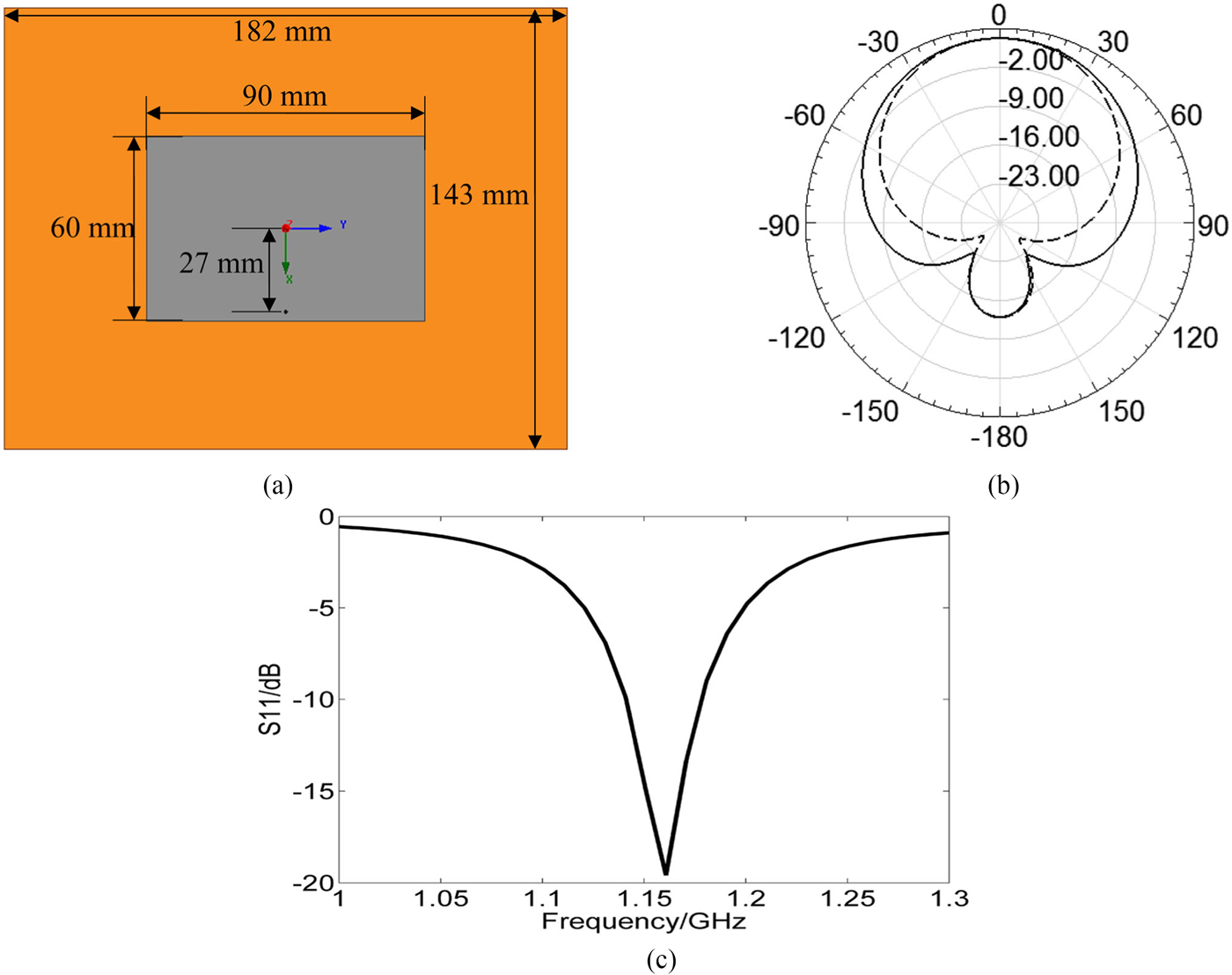
We used a conventional microstrip antenna as the reference antenna, as shown in Fig. 1(a), where the yellow area represents the reference antenna substrate, and the gray area represents the patch. The coordinate axis origin was set at the antenna center. The substrate was FR4 with relative permittivity 4.4, loss tangent 0.02, and dimensions 182 × 143 × 2 mm; patch dimensions were 90 × 60 mm; and the ground plane was the same size as the substrate. The reference antenna was fed coaxially with the feed point 27 mm from the origin along the positive x-axis.

Fig. 1. Geometry and simulation results of the reference antenna. (a) Geometry. (b) Radiation patterns. (c) Reflection coefficient.
Figure 1(b) shows the reflection coefficient and Fig. 1(c) shows the radiation pattern. The reference antenna had working frequency band 1.12–1.17 GHz with 1.16 GHz resonance, and 3.2 dB maximum gain. All simulations in this study were performed using HFSS 13.0 software.
Antenna RCS is composed of structural and antenna mode RCS [Reference Genovesi, Costa and Monorchio11],
 $$\sigma \, {\rm =}\, \left \vert {\sqrt {\sigma_s} -\lpar {1 + \Gamma_a} \rpar \sqrt {\sigma_a} e^{\,j\phi}} \right \vert ^2,$$
where σ, σ S, and σ a are total, structural, and antenna mode RCS, respectively; Γa is the reflection coefficient, and φ is the relative phase between the modes.
In this paper, we assume antenna impedance is well matched, i.e., antenna mode RCS is constant. Therefore, antenna RCS reduction can be obtained by reducing structural mode RCS. According to the method in references [Reference Dikmen, Cimen and Cakir12–Reference Dikmen and Cakir16], the metal area with the weak distribution can be removed to reduce antenna RCS with the radiation performance maintained. Therefore, the distribution of reference antenna should be analyzed first.
Since we want to maintain performance while reducing antenna RCS, we first analyze surface current distribution at the working frequency in radiating mode, as shown in Figs 2(a) and 2(b) for patch and ground planes, respectively. Arrows represent surface current direction at each position, and their density represents surface current amplitude.

Fig. 2. Surface current distribution in the radiating mode of the reference antenna. (a) Patch plane. (b) Ground plane.
Patch plane surface current direction is parallel to the x-axis, and spreads from the bottom to the top of the patch with current along the bottom of the patch spreading from the sides to the middle. Thus, current in the middle region is stronger than along the bottom and top.
Most ground plane current is distributed beneath the patch, with very little and low-density current near the ground plane edges. Therefore, radiation performance could be largely maintained if subtraction is introduced on the ground plane and close to the edges while the patch remained without modification.
The incident wave was θ polarized with normal incidence in scattering mode. We analyzed current distributions for 1–4.4 GHz with 0.1 GHz step to facilitate simultaneous in-band and out-of-band RCS reduction. However, only four cases (1.16, 1.4, 2.7, and 3.4 GHz) are discussed here due to space considerations, as shown in Fig. 3 for scattering mode.

Fig. 3. Current distribution in scattering mode of reference antenna in different frequencies. (a) 1.16 GHz. (b) 1.4 GHz. (c) 2.7 GHz. (d) 3.4 GHz.
There is a strong surface current beneath the patch, with additional strong current located around two sides of the ground plane. Therefore, the area beneath the patch should not be modified, following the shaping principle that only weak distribution areas should be subtracted [Reference Yu, Gong and Hong.22]. However, the subtracted area should be large enough to effectively reduce RCS, i.e., at least half of the metal plate [Reference Liu, Li, Jia, Hao, Gong and Guo23]. Smaller subtraction may fail to obtain sufficient RCS reduction for far less than the wavelength, which leads to no effect on the structural RCS of the antenna.
Proposed modified antenna
Figure 4(a) shows a top view of the modified antenna, designed based on the previous (reference antenna) analysis. The blank areas represent the subtracted slots. The modification consists of 14 slots, detailed in Fig. 4(b), numbered from 1 to 14. Dark plots show slot vertices of the slots, and the coordinates of the vertices described as (X m, Y m), with L m and W m being slot length and width, respectively; and m = 1,…, 14 is the slot number.

Fig. 4. Geometry of the modified antenna. (a) Front view. (b) Geometry of the 14 slots on the ground plane.
Table 1 summarizes the optimized structural parameters, but the optimization process is not presented here for brevity. Each parameter was optimized to minimize antenna monostatic RCS. All the slots were subtracted from the ground plane, and the modified antenna is the same size as the reference antenna and constructed from the same material.
Table 1. Values of all the slots

Figures 5 and 6 show simulated reflection and radiation patterns, respectively, for the reference and modified antenna. The modified antenna has 1.16 GHz working frequency with 50 MHz bandwidth, and maximum gain 0.8 dB larger than the reference antenna. Thus, the proposed modifications had no effect on radiation performance compared with the reference antenna.

Fig. 5. Comparison of reflection coefficient between the reference and modified antenna.

Fig. 6. Comparison of radiation pattern between the reference and modified antenna. (a) E-plane. (b) H-plane.
Figure 7 shows compared RCS for the two antennas, and the incident wave was θ polarized and normal incidence. The modified antenna exhibits lower RCS than the reference antenna throughout 1–4.4 GHz, and the reduction includes in-band and out-of-band RCS simultaneously. Modified antenna RCS is significantly reduced at 1.16, 2.7, and 3.4 GHz, by 16.3, 17.9, and 19.3 dBsm, respectively. The modified antenna achieved maximum 16.3 dBsm in-band RCS reduction at 1.16 GHz and maximum 19.3 dBsm out-of-band RCS reduction at 3.4 GHz, respectively, and at least 5 dBsm RCS reduction across the entire frequency band (1–4.4 GHz). Relative RCS reduction bandwidth at the working frequency (1.16 GHz) was 293%. Thus, the proposed modified antenna achieved wideband RCS reduction.

Fig. 7. Comparison of monostatic RCS between the reference and modified antenna.
Figure 8 shows that surface current distributions of the modified antenna in radiating mode have the same amplitudes as the reference antenna (Fig. 2), i.e., surface current intensity remains closely comparable to the reference antenna. Although some parts of the ground plane have been subtracted, causing surface current direction changes in the ground plane, these surface changes are too weak to affect antenna radiation performance. Thus, the proposed modifications have maintained radiation performance.

Fig. 8. Surface current distribution in the radiating mode of the modified antenna. (a) Patch plane. (b) Ground plane.
Figure 9 shows surface current distributions for the modified antenna in scattering mode. Many other frequencies were analyzed, but omitted here for brevity. Surface current amplitude increased after modification (compare Figs 2 and 9). Removing weak current regions focused surface current focuses on the left area of the ground plane, leading to increased surface current intensity, and hence reduced antenna RCS.

Fig. 9. Current distribution in scattering mode of the modified antenna in different frequencies. (a) 1.16 GHz. (b) 1.4 GHz. (c) 2.7 GHz. (d) 3.4 GHz.
Fabrication and measurement
Prototype reference and modified antennas were fabricated and measured, as shown in Fig. 10, to verify the simulation. Reflection coefficients were measured using an Agilent E8363B vector network analyzer, with the prototypes welded by the SMA connector and connected by the feed line, as shown in Fig. 11. Reference and modified antenna prototypes working frequencies were 1.15 and 1.16 GHz, respectively. A comparison between the gain measured for reference antenna and modified antenna is exhibited in Fig. 12(a). It shows that the two prototype antennas almost have the same gain within the working frequency band. Thus, antenna radiation performances are almost identical, which is consistent with the simulation.

Fig. 10. Pictures of the two fabricated antennas. (a) Top view. (b) Bottom view.

Fig. 11. Measurement and results of the experiment. (a) Measured result of the return loss. (b) Experimental setup. (c) Measured result of the E-plane radiation patterns. (d) Measured result of the H-plane radiation patterns.

Fig. 12. (a) Measured gain of the modified and reference antenna. (b) Measured monostatic RCS.
The RCS for both antenna prototypes were measured in a microwave anechoic chamber using an Anritsu MS4644A vector network analyzer connected to the feed line. Two horn antennas were used as the transmitter and receiver. The prototype was placed on the middle of the workbench and fixed using plastic foam, which has similar dielectric constant to air, and arranged to ensure prototype and horn centers were aligned and the same height.
Figure 12(b) compares measured RCS for the two prototypes. Measured RCS of the modified antenna is lower than that of the reference antenna from 1 to 4.4 GHz. Antenna RCS was reduced across the frequency range. The discrepancies between simulated and measured results are due to fabrication tolerances and measurement (position) errors.
Generally, prototype measurement verified the simulation, and the proposed modified antenna exhibited significant and simultaneous reduced in-band and out-of-band RCS across a wide frequency band, while maintaining radiation performance.
Conclusions
This paper proposed a modified microstrip antenna to simultaneously reduce in-band and out-of-band RCS. Table 2 compared the modified antenna RCS performance with previously developed antennas. Of these, only the antenna developed in [Reference Zhao, Gao, Cao, Liu, Xu, Liu and Cong8] obtained simultaneous in-band and out-of-band RCS reduction, but the reduction frequency range was narrow. In contrast, the proposed antenna successfully reduced in-band and out-of-band RCS simultaneously while maintaining radiation performance compared with the reference antenna.
Table 2. Comparison of RCS performance in the references

The proposed antenna exhibited maximum in-band and out-of-band RCS reductions of 16.3 dBsm at 1.16 GHz and 19.3 dBsm at 3.4 GHz, respectively, with significant RCS reduction across 1–4.4 GHz, i.e., wideband RCS reduction. The proposed antenna is relatively simple to fabricate and integrate, and would be suitable for stealth applications where low RCS is the main concern and antenna volume is limited.
 JiaKai Zhang was born in Shannxi Province, China, in 1990. He received the M.Sc. and B.Sc. degrees in School of Electronics and Information, Northwestern Polytechnical University in Xi'an city, China, in 2012 and 2015, respectively. He is presently working on his doctoral degree in School of Electronics and Information, Northwestern Polytechnical University in Xi'an city, China. His research interests include electromagnetic metamaterials and antenna RCS reduction study. E-mail: zjkyikun@mail.nwpu.edu.cn
 Jiachen Xu was born in Shannxi Province, China, in 1991. He received the B.Sc. and M.Sc. degrees in the School of Electrical and Information, Northwestern Polytechnical University in Xi'an city, China, in 2013 and 2016, respectively. He is presently working on his doctoral degree in School of Electronics and Information, Northwestern Polytechnical University in Xi'an city, China. His research interests include dielectric resonator antennas and shared aperture array. E-mail: xujiachen9151@outlook.com
 Yan Qu was born in Xinjiang Province, China, in 1987. He received the B.Sc. degree in Electronic and Information Engineering and Ph.D. in Electronic Science and Technology from the School of Electronic and Information, Northwestern Polytechnical University, 2010 and 2017. He is now working in China Academy of Space Technology (Xi'an) as an antenna engineer. His research interests include phased-array antenna design and synthesis. Email: quyan0908@126.com
 Jun Ding was born in Shannxi Province, China, in 1964. She received the M.Sc., B.Sc., and Ph.D. degrees in School of Electronics and Information, Northwestern Polytechnical University in Xi'an city, China, in 1986, 1989, and 2005, respectively. She is a professor in School of Electronics and Information NWPU. She has published more than 100 research papers. Her research interests include electromagnetic metamaterials, the antenna theory and design, and the microwave circuit design. E-mail: dingjun@nwpu.edu.cn
 Chenjiang Guo was born in Shannxi Province, China, in 1963. CIE Senior Member, Antenna Society Committee Member. He received the M.Sc., B.Sc., and Ph.D. degrees in School of Electronics and Information, Northwestern Polytechnical University in Xi'an city, China, in 1984, 1987, and 2007, respectively. He is a professor in School of Electronics and Information NWPU. He has published more than 140 research papers. His research interests include EMI/EMC, the antenna theory and design, and the microwave circuit design. E-mail: cjguo@nwpu.edu.cn